
Why Are Aluminum Alloy Sheet-Metal Weldments Prone to Distortion and Softening?
For aluminum sheets of approximately 1–1.5 mm thickness, some projects select TIG, others use pulsed MIG, and still others evaluate laser welding. The deciding factors are not limited to sheet thickness; they also include the material grade and temper, joint configuration, weld length, cosmetic surfaces, assembly tolerances, production volume, and inspection level. When an aluminum alloy sheet-metal weldment must combine low distortion, sufficient penetration, and stable assembly, the process should be selected before quotation and prototyping, rather than waiting to remedy distortion after welding.
Aluminum conducts heat rapidly, so welding heat quickly spreads into the surrounding sheet; it also has relatively high thermal expansion, and localized heating and cooling shrinkage can easily cause angular distortion, warpage, or misalignment. Certain aluminum alloy tempers may also experience a loss of strength in the heat-affected zone. Therefore, excessive heat input can lead to burn-through, an enlarged heat-affected zone, and post-weld dimensional drift; insufficient heat or unstable gaps may result in lack of fusion. Improper control of the surface oxide film, oil contamination, or shielding conditions can also increase the risk of porosity.
Different defects require different corrective approaches: burn-through generally calls for reevaluating heat input, welding speed, and joint gap; lack of fusion requires checking the joint preparation or lap condition, penetration depth, and parameter stability; porosity is closely related to cleaning, shielding-gas coverage, and surface preparation. Insufficient fixture restraint can amplify angular distortion, but excessive clamping can also convert free shrinkage into residual stress, with springback still occurring after release. Ultimately, a weldment that cannot be assembled after welding is often not the result of a single welding parameter, but of the combined effects of the joint, fixture, welding sequence, and dimensional tolerances.
TIG, Pulsed MIG, or Laser Welding: How Should You Choose for Aluminum Alloy Sheet Metal?
For aluminum alloy sheet metal approximately 1–1.5 mm thick, the welding process cannot be selected based on sheet thickness alone. Joint configuration, weld length, visible welds, assembly tolerances, production volume, and inspection level can all change the trade-offs among TIG, pulsed MIG, and laser welding. The following comparison is suitable as an initial review framework for aluminum alloy sheet-metal weldments, not as a fixed division between processes.
| Process | Heat Input and Filler Method | Suitable Applications | Primary Advantages | Key Limitations and Inspection Implications |
|---|---|---|---|---|
| TIG | Non-consumable tungsten electrode; the arc, heat input, and filler wire can be controlled relatively independently | Thin walls, short welds, visible welds, and dimension-sensitive joints | Weld appearance is relatively easy to control, making it suitable for fine adjustments | Typically slower and more sensitive to cleanliness, operator stability, and joint gap; long welds may still accumulate heat and cause distortion |
| Pulsed MIG | Continuous wire feeding, with pulse parameters used to adjust droplet transfer and heat input | Longer welds, structural components, and higher-volume assemblies | Continuous wire feeding generally provides a faster production cycle than TIG, allowing a compromise between efficiency and heat input | Requires high stability in wire feeding, shielding gas, parameters, and fixturing; variations in misalignment or joint gap may increase the risk of lack of fusion, burn-through, and dimensional deviations |
| Laser Welding | A high-energy-density heat source with the potential to minimize weld penetration and the heat-affected zone | Assemblies with stable gaps, higher production volumes, and sensitivity to thermal distortion | Offers advantages in welding speed and localized heat control; the heat-affected zone is generally relatively narrow | The reflectivity and surface condition of aluminum, as well as the assembly gap, affect process stability; porosity, cracking, and internal defects must be confirmed through targeted parameter validation and appropriate inspection |
For small-batch aluminum alloy sheet-metal weldments with short welds and prominent visible surfaces, TIG is often easier to manage through manual control of heat and filler addition; however, this does not mean that TIG is required for all sheet-metal applications. For components with longer welds or where production cycle time takes priority, pulsed MIG may be more suitable, provided that the joint gap, wire feeding, and fixture condition remain stable. For laser welding, assembly accuracy, surface preparation, and process-validation conditions should be confirmed first; it should not be selected solely because it offers a “small heat-affected zone.”
The final decision must also return to assembly and acceptance requirements: if flange flatness, hole position, or interface gap is critical, post-weld dimensional remeasurement should be included in first-article validation. If the part serves a sealing or load-bearing function, the requirements for appearance, dimensions, leakage, or internal-defect inspection should be defined in advance in the drawing or project specification. The core of process selection is not to determine which welding method is “best,” but to establish a verifiable balance among heat input, distortion, efficiency, appearance, and inspection.
Where Does Distortion in Aluminum Alloy Sheet-Metal Welding Begin: The Joint, the Fixture, or the Parameters?
Distortion in aluminum alloy sheet-metal weldments often does not begin when the welding torch is started; the risk is already embedded during the material, joint, and fixturing review stages. Before quoting or producing samples, first confirm the sheet grade and temper, thickness, weld location and length, joint gap, misalignment requirements, and the flatness, angle, hole position, and assembly datums that must be maintained after welding. Different sheet conditions may exhibit different softening and springback behavior after heating; therefore, the process cannot be determined solely by the fact that the material is “thin sheet.”
Joint gaps and weld layout determine the shrinkage path
An excessive joint gap typically requires more filler metal and heat, which may increase the risk of burn-through, angular distortion, or post-weld shrinkage; an unstable gap can easily cause lack of fusion, variations in weld size, and mismatch. Long, continuous welds also concentrate heat along the same shrinkage path, potentially causing the flanges of thin-wall enclosures or the ends of T-brackets to deflect toward the weld side. Weld length, accessibility, and whether intermittent or staggered welding can be used should all be evaluated during the structural review.
Fixture restraint and welding parameters need to be evaluated together
Fixtures are not necessarily better when clamped tighter. Moderate positioning can stabilize the gap and limit free deformation, but excessive restraint may convert visible deformation into residual stress, with springback or dimensional changes still occurring after the fixture is released. Locating points, clamping force, heat dissipation paths, torch accessibility, and release sequence should all be incorporated into fixture design; for parts with relatively frequent changeovers, fixture complexity must also be weighed against repeatable positioning capability. Welding parameters should be validated together with the joint condition, heat accumulation, and weld sequence rather than based solely on the appearance of a single weld pass. Final dimensions should be remeasured after natural cooling and unclamping as specified; readings taken inside the fixture cannot directly replace the delivered condition.
How to control distortion when welding thin aluminum alloy sheet: from pre-weld preparation to post-weld remeasurement
Distortion control in thin aluminum alloy sheet welding should not be addressed only after welding. The material grade and temper, sheet thickness, joint gap, locating datum, and weld length should all be confirmed during the process review. For thin sheets of approximately 1–1.5 mm, any localized concentration of heat may affect the flange plane, hole positions, or subsequent assembly; this range is merely an example for process discussion and is not a fixed dividing line between TIG and MIG.
Before welding: stabilize the joint and measurement datums first
Before welding, inspect the sheet surface cleanliness, joint gap, mismatch, and assembly fit, and clearly define which dimensions are located by the fixture and which are measured from the part datums. Unstable cleaning and protection conditions may increase the risk of defects such as porosity; an excessive gap may force the welder to increase heat input, raising the likelihood of burn-through or angular distortion. For dimensionally sensitive enclosures, brackets, and flanged housings, the necessary preset counter-distortion may be established based on trial-welding results, but an empirical angle must not be treated as a fixed value for all structures.
During welding: distribute heat rather than simply tightening the clamps
The fixture should provide stable positioning, moderate clamping, and a controllable heat dissipation path. If clamping is too loose, the joint may move; if it is too tight, free shrinkage may be converted into residual stress, resulting in springback after the fixture is released. For longer welds, intermittent, skip, symmetrical, or staggered sequences can be used to reduce the continuous accumulation of localized heat. The specific sequence must be validated according to the structure, weld accessibility, and clamping method and cannot be applied indiscriminately.
After welding: remeasure thin aluminum alloy sheet weldments after unclamping
After welding, allow the part to cool naturally as required by the process, then release the fixture in the specified sequence and re-establish the measurement datums. Inspection should not be limited to weld appearance; it should also include flatness, angles, hole positions, flange location, end spacing, and assembly gaps with mating parts. A dimension that is acceptable inside the fixture does not necessarily remain acceptable in the free state. Final acceptance should be based on drawing tolerances and functional requirements; if repeated rework occurs, trace back the heat input, joint gap, fixture restraint, and welding sequence rather than forcibly straightening the part only after welding.
Why should T-brackets and thin-wall enclosures use intermittent, symmetrical, or staggered welding?
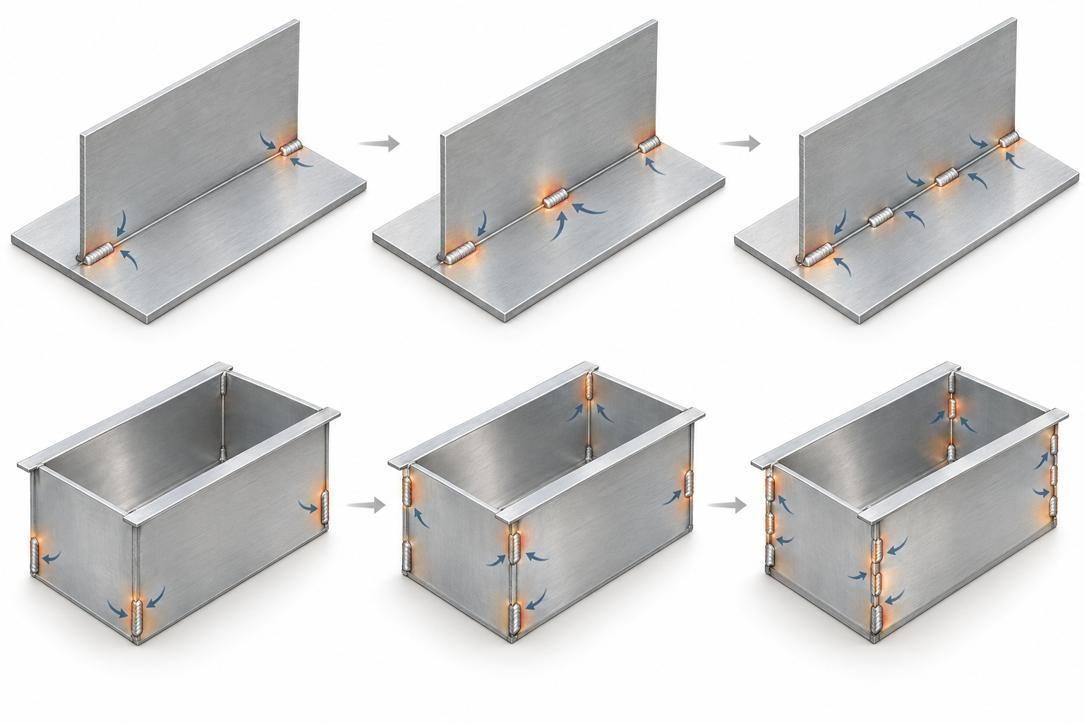
The welding sequence for thin aluminum alloy sheet weldments cannot be determined solely by whether the weld can achieve fusion; the way heat is distributed throughout the structure must also be considered. Take a flanged thin-wall enclosure as an example: if one long edge is welded continuously, heat becomes concentrated in a localized area. The weld and the surrounding material first expand and then contract, making the flange prone to warping toward the weld side. T-brackets present a similar issue: completely welding one side's long weld before addressing the other side may amplify angular distortion at the ends or cause the vertical plate to deviate from its perpendicular position.
Therefore, for a specific T-shaped structure, the weld can be divided into several sections and an intermittent, symmetrical, or staggered sequence can be used to allow localized heat time to dissipate and alter the direction of continuous shrinkage. For example, first tack and weld relatively dispersed short sections, then return to the middle or the opposite side to complete the welds; this can help prevent heat from accumulating at the same end for an extended period. The specific sequence must still be determined in conjunction with the joint gap, fixture restraint, weld accessibility, and actual prototype results; millimeter-level distortion results from research specimens cannot be directly converted into delivery guarantees for other parts.
Which dimensions of thin aluminum alloy sheet weldments should be inspected after unclamping and cooling?
After welding is complete, the result should not be assessed only while the part is in the fixture. Allow it to cool naturally as specified, then re-establish the measurement datums after releasing the fixture and inspect flange flatness, vertical-plate perpendicularity, end spacing, hole positions, and assembly gaps with mating parts. For thin-wall enclosures, also check whether the opening dimensions, cover interfaces, and sealing surfaces have become misaligned due to angular distortion. If the structure is required to bear loads or provide sealing, final acceptance dimensions should correspond to functional testing and drawing tolerances rather than being judged solely by weld appearance.
How should a quality inspection plan be developed for thin aluminum alloy sheet weldments?
The inspection plan for aluminum alloy thin-sheet welded parts should not begin with “Is non-destructive testing required?” Instead, it should work backward from the drawings, functional requirements, and failure risks. Visual and dimensional inspections answer different questions; further confirmation of internal defects or leak performance is needed only when sealing, load-bearing, or fatigue requirements are demanding. The specific acceptance level must also reference the applicable project standards, customer specifications, or confirmed first-article requirements, and cannot be inferred from sheet thickness alone.
Aluminum alloy thin-sheet welded parts should undergo visual and dimensional inspection first
Visual inspection primarily confirms whether the weld is continuous and uniformly formed, and whether there are obvious pores, undercut, cracks, burn-through, lack of fusion, or excessive spatter. Dimensional inspection should be performed after natural cooling, the fixtures have been released as agreed, and the measurement datum has been re-established. Key items to record include mismatch, angles, flatness, flange position, hole locations, and assembly clearances. For thin-walled boxes with flanges, an acceptable weld appearance does not necessarily mean that the box can be assembled; critical interface dimensions must still be verified using suitable methods such as measuring tools, inspection fixtures, or a coordinate measuring machine.
Select special inspections according to the function of aluminum alloy thin-sheet welded parts
If the part serves a sealing function, the drawings or acceptance documents should clearly specify the leak-test method, medium, pressure, and acceptance criteria; visual inspection cannot replace sealing verification. When the risks associated with load-bearing, fatigue, or internal defects are high, penetrant, radiographic, or ultrasonic testing may be evaluated based on the joint structure, inspection accessibility, and applicable specifications. Different methods detect different types of problems, and not all thin-sheet welded parts automatically require radiographic or ultrasonic testing. Before quotation and first-article review, it is recommended to provide the material grade and condition, sheet thickness, weld drawing, critical tolerances, functional requirements, inspection level, and record format so that the supplier can arrange process validation and dimensional reinspection accordingly.
What information is required for aluminum alloy thin-sheet welding before requesting a quotation and producing samples?
The process for aluminum alloy thin-sheet welded parts cannot be determined from a 3D model alone. Before requesting a quotation or producing samples, provide the material grade and condition, sheet thickness, 3D part model, and 2D weld drawing, and specify the joint type, weld length, whether continuous welding is required, cosmetic surfaces, and the locations of inaccessible welds. A sheet thickness of approximately 1–1.5 mm does not constitute a fixed dividing line between TIG, pulsed MIG, and laser welding; joint gap, production volume, assembly tolerances, and inspection level also affect process selection.
- Dimensions and assembly: List the critical flatness, perpendicularity, hole locations, flange positions, mismatch, and assembly clearances, and specify the measurement datum.
- Production information: State the prototype quantity, stable production volume, changeover frequency, and whether long continuous welds are present, so that the cycle time and fixture investment for manual TIG, pulsed MIG, or laser welding can be assessed.
- Quality requirements: Clearly define the appearance grade, weld continuity, sealing or load-bearing function, and the applicable requirements for visual, dimensional, leak, penetrant, radiographic, or ultrasonic inspection.
- Historical data: Provide deformation, porosity, lack of fusion, burn-through, rework locations, and measurement records from existing samples. This information helps identify risks related to heat input, gaps, or fixturing in advance.
Once the information is complete, the supplier can assess weld accessibility, locating points, and the fixture-release sequence, and arrange first-article validation. The acceptance agreement should also specify the natural-cooling conditions, unclamped state, and measurement datum: dimensions in the fixture may differ from those after release, so the unclamped final assembly condition cannot be judged using measurements taken while the part remains clamped. For dimension-sensitive aluminum alloy thin-sheet welded parts, confirming these inputs before discussing the process and quotation is generally more controllable than reworking the parts after welding.
Frequently Asked Questions (FAQ) About Aluminum Alloy Thin-Sheet Welded Parts
The process, deformation, and inspection of aluminum alloy thin-sheet welded parts cannot be judged by sheet thickness alone. The following questions address common misconceptions in process selection, fixture control, and acceptance planning.
Must aluminum sheet approximately 1–1.5 mm thick always be welded using TIG?
Not necessarily. TIG generally facilitates fine control of heat input and filler addition, making it suitable for short welds, visible welds, or dimension-sensitive joints. However, joint type, gap, material condition, weld length, and production volume are equally important. Pulsed MIG or laser welding may also be suitable, subject to sample testing to confirm the risks of burn-through, fusion, and deformation.
When is pulsed MIG more suitable than TIG?
When an aluminum alloy assembly has long welds, a relatively high production volume, or requires continuous wire feeding to improve production efficiency, pulsed MIG may be more suitable. The prerequisites are stable wire feeding, shielding gas, joint gaps, and fixturing, with heat input capable of meeting appearance, dimensional, and assembly requirements. It is not the default choice for every thin-sheet structure.
Does tighter fixturing necessarily reduce deformation when welding aluminum alloy thin sheet?
Not necessarily. Proper locating can limit displacement during welding, but excessive restraint may increase residual stress, and springback or dimensional changes may still occur after the fixture is released. Clamping force, locating points, heat-dissipation paths, and the release sequence should be validated in combination with the structure. Critical dimensions should be remeasured after natural cooling and unclamping.
Do all aluminum alloy sheet metal weldments require radiographic or ultrasonic inspection?
Not as a default requirement. Visual and dimensional inspections are typically performed first to verify weld appearance, continuity, misalignment, angles, and assembly datums. Whether to add leak, penetrant, radiographic, or ultrasonic testing should be determined based on sealing requirements, load-bearing requirements, fatigue, the risk of internal defects, joint accessibility, and the customer's drawings or applicable standards.
Key takeaways
- Aluminum alloy sheet-metal welding processes should consider sheet thickness, joint configuration, weld length, cosmetic surfaces, production volume, tolerances, and inspection level together, rather than simply comparing TIG and MIG.
- TIG generally facilitates control of heat input and filler addition; pulsed MIG is better suited to longer welds and structural parts where efficiency is the priority; laser welding, meanwhile, depends on stable gaps, surface preparation, and thorough process validation.
- Distortion control starts with assembly and fixturing. It should incorporate joint gaps, fixture restraint, presetting, segmented welding, and symmetrical or staggered sequences, followed by remeasurement of critical dimensions after unclamping and natural cooling.
- Quality inspection should be driven by the drawing and functional risks: begin with visual and dimensional inspection, then determine whether to add nondestructive testing or leak testing based on the risks associated with sealing, load bearing, fatigue, and internal defects.
- Providing the material grade and temper, thickness, weld drawing, critical tolerances, cosmetic surfaces, production volume, and acceptance requirements before requesting a quotation helps suppliers properly assess process and fixturing risks.



