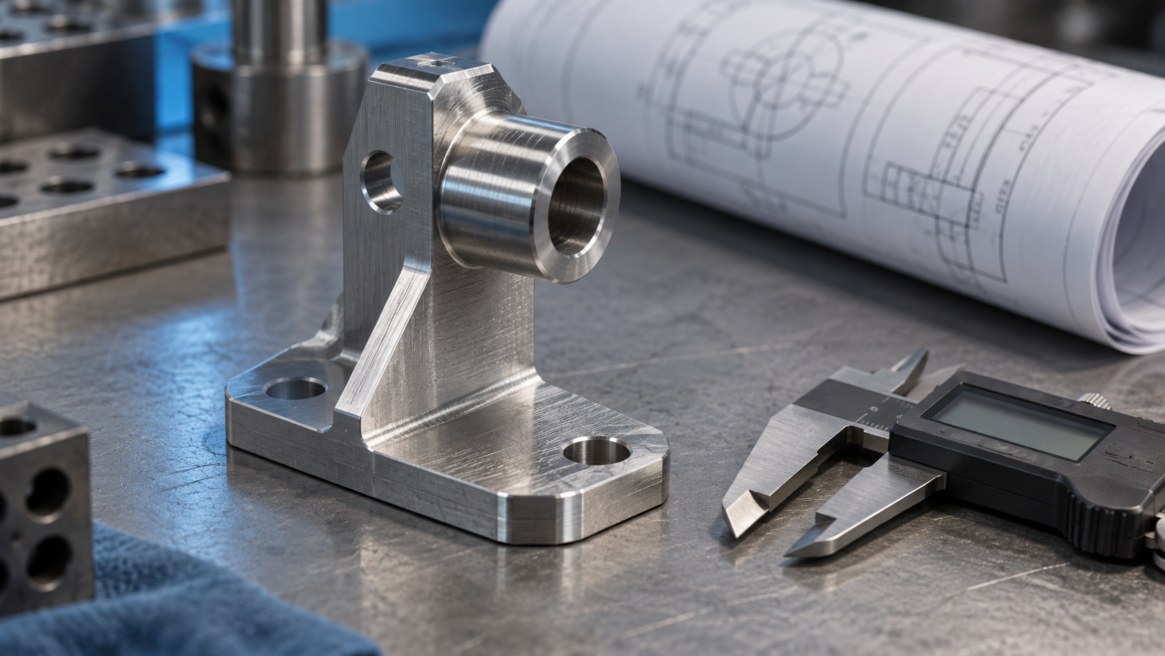
What Are Custom Parts? First Distinguish Standard Parts from Non-Standard Parts
To understand custom parts, it is best to start from their opposite—standard parts. Bolts, nuts, washers, and rolling bearings have long been fully standardized in structure, dimensions, drawing methods, and markings, and are mass-produced by specialized factories according to unified specifications. When purchasing, you only need to state the specification and model, and the products you receive can be directly interchanged among different manufacturers. The logic of standard parts is: unified specifications, the same no matter who makes them.
Non-standard parts take a different path. The industry defines non-standard parts as follows: the state has not established strict standard specifications and parameter regulations, they are independently controlled by the enterprise, and they are customized according to the customer's drawings or specific requirements. In other words, there is no universal model to look up, and the specifications are defined individually by this drawing and this batch of requirements. Standard parts are "selected"; non-standard parts are "made."
Simplified Classification of Non-Standard Parts: Metal and Non-Metal
There is no very standardized classification system for non-standard parts. In the industry, they are usually divided into two categories by material: metal parts and non-metal parts. Metal non-standard parts often start from casting or bar stock and end with finishing, with quality control throughout the entire process, making the process complex and highly variable; non-metal parts more often involve engineering plastics, acrylic, rubber, etc., and their processing methods and heat treatment logic are completely different. This dichotomy is only a simplified framework to help first determine the process direction, and does not replace specific material selection.
It is precisely because there are no unified specifications that the cost and process complexity of custom parts are usually higher than standard parts. Standard parts can spread tooling and setup costs through batch volume, while each batch of non-standard parts is equivalent to going through process preparation all over again, so the development cycle is naturally longer. This is an inherent property of non-standard parts, not low efficiency at any particular factory.
Typical Process Chain for Custom Non-Standard Precision Parts
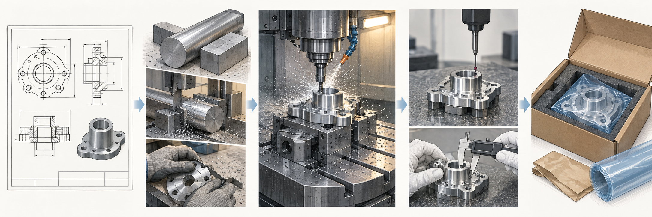
Standard parts can be ordered from a catalog; custom parts cannot. Non-standard parts have no unified specifications, their processes cannot be copied, and they can only be confirmed step by step according to the drawing. The chain below is broken down by "input—action—output," and the following sections will expand each part.
The reason this chain is much longer than for standard parts lies in variability: metal non-standard parts often require quality control throughout the entire process from casting or forging to finishing, and if the datum or allowance in any intermediate step is not set correctly, rework will be required later. It is also precisely because the process is complex that the cost and lead time of custom parts are usually higher than standard parts of the same specifications. This is not a manufacturer markup, but is determined by the process itself.
Upfront Preparation and Drawing Analysis: The First Gate for Custom Parts
Whether an order for custom parts (non-standard parts) succeeds is often 70% to 80% determined before work begins. When the drawing is sent over, the first thing the manufacturer must do is not quote, but read all the information thoroughly: dimensions, shape, material, tolerances, and then look deeper at structure, dimensional accuracy, geometric tolerances, and surface roughness. If any one of these is vague, it may later turn into drawing changes, rework, or a price increase.
What the Customer Must Provide: A Drawing Alone Is Not Enough
A 2D engineering drawing plus a 3D model is usually only the starting point. For custom parts to actually enter production, the customer must at least clarify three things:
- Datums and critical dimensions: which face is the datum, which dimensions are assembly functional dimensions, and which are only reference. The clearer the callouts, the less back-and-forth confirmation is needed.
- Material and condition: whether it is 6061-T6 or 304, whether heat treatment is required, and whether plate or bar stock is specified will all affect cost and subsequent processes.
- Quantity and use: single-piece prototyping, small-batch trial production, or production ramp-up directly determines whether CNC or another method is used, and also determines whether dedicated inspection fixtures are needed.
The cost of missing drawing information is very concrete: for a mating hole with no tolerance specified, the manufacturer works to free tolerance, and when assembly reveals it does not fit, it must be machined again. The problem is not in the workshop, but at the drawing stage, where functional requirements were not translated into manufacturing language.
What the Manufacturer Must Confirm: From Drawing to Manufacturability
After receiving the drawing, the manufacturer's confirmation actions usually include: whether the structure can be reached by standard tools, whether thin walls or deep cavities will deform during machining, whether geometric tolerances conflict with the fixturing method, and whether surface roughness requirements need additional grinding or polishing. Making these confirmations upfront is much cheaper than stopping halfway through to make changes.
If you have a clear drawing and quantity on hand, doing a round of manufacturability checks before entering quotation is a relatively reliable way to start custom parts. This step does not solve all problems, but it can expose most places where something is "feasible in design but awkward to machine" in advance.

Writing acceptance criteria into the drawing is cheaper than arguing afterward over who is right and who is wrong. This is especially true for custom parts—non-standard parts have no unified standard specifications to rely on, so the drawing is the only shared basis for both parties.
Material Selection and Preprocessing: The Starting Point for Custom Part Performance
Drawing analysis for custom parts determines "shape and tolerances"; the next step is to lock down the material. Once the material enters the workshop, all subsequent processes—cutting parameters, fixturing methods, stress relief arrangements, and surface treatment—must revolve around it. Choosing the wrong material often does not mean scrapping one piece, but rather dimensional drift across the entire batch and rescheduling. Therefore, this section only discusses the selection logic: first lock the material category by use, then weigh metal versus non-metal, and finally buy back dimensional stability through preprocessing.
First Look at Use, Then Look at Metal and Non-Metal
Application determines the upper limit of the material category. Load-bearing structural parts, kinematic pairs, and sealing surfaces usually prioritize metals; housings, flow-guide parts, insulating parts, and lightweight brackets are often more cost-effective in non-metals. Within metals, further distinctions apply: carbon steel and alloy steel offer high strength and low cost, but corrosion resistance must be supplemented by plating or coatings; stainless steel has good corrosion resistance but a pronounced tendency toward work hardening, causing rapid tool wear during cutting; aluminum alloy has low density and good machinability, but its stiffness is inferior to steel, and long overhangs tend to cause tool deflection; copper alloys offer good thermal and electrical conductivity but are price-sensitive. Among non-metals, engineering plastics excel in weight, chemical resistance, and electrical insulation, at the cost of limited stiffness, temperature resistance, and creep performance.
A common misconception needs clarification: temperature resistance is not about "whether it can touch hot water." High-temperature specialty plastics common in the industry (such as PEEK, PEI, PPS, and the like) can typically work long-term in high-stress environments at 150°C–350°C, with the specific upper limit depending on the grade, filler system, and load duration; this is an example of material capability, not a guarantee by any particular company. If custom parts are used near engine compartments, ovens, or sterilization equipment, material selection must separate "peak temperature" and "continuous temperature" and write both into the drawing.
Pretreatment: Buy dimensional stability up front
Many custom parts are not impossible to machine—they simply change after sitting for two days post-machining. Rough machining removes a large amount of material, redistributing internal stresses, which is especially pronounced in thin-walled parts, long shafts, and large plates. A common practice is to schedule stress-relief annealing after rough machining, then finish machine; for aluminum alloy, the stress-relief temperature and holding time must be confirmed by grade and cannot be copied from steel curves. Castings and forgings are also generally recommended to undergo a stabilization treatment before entering finish machining.
Non-metals require a different pretreatment approach: plastic parts must be dried before machining or injection molding; moisture-absorbing nylon and PC will develop silver streaks, bubbles, and dimensional deviations if molded directly; some materials require drying at the supplier-specified temperature and time, rather than just "baking for a while." Metal parts need rust prevention during inter-process waits, especially carbon steel parts between stress relief and waiting for finish machining—skip one rust-prevention step and you may add grinding and rework later.
The selection logic boils down to three sentences: First determine the category by load, temperature, medium, and weight; then compare machinability, corrosion resistance, and cost within the same category; finally lock in dimensional stability with stress relief, drying, and rust prevention. The material list does not need to be padded, but these three sentences must be turned into explicit grades, conditions, and heat treatment requirements in the drawing or technical agreement. Custom parts with vague grades usually have uncontrollable quotes and lead times.
What equipment is used for custom non-standard parts machining? Five categories by application
Searching for "custom non-standard parts machining equipment" easily returns a string of models and brands. A more useful classification for procurement and engineers is grouping by application: what problem does this machine solve, rather than what it is called. The process chain for custom parts spans welding, cutting, forming, machining, post-processing, and inspection, and the same batch of parts often moves between several equipment categories. Below, the responsibility boundaries of each of the five categories are clarified.
Welding and cutting: solving connection and blanking
Common welding equipment includes butt welders and TIG welders. The former is used for butt-joining bars, wire, and profiles; the latter is used for forming welds on thin-walled parts such as stainless steel and aluminum, with a small heat-affected zone and good weld bead formation. Common cutting equipment includes abrasive wheel cutters, air plasma cutters, and angle grinders: abrasive wheel cutting suits profile blanking, plasma cutting is used for contour blanking of medium-thick plates, and angle grinders are mostly used for deburring and post-weld dressing. This category determines "whether the material can be cut and whether the parts can be joined," and is the preparatory process before custom parts enter finish machining.
Forming and machining: the main body of shape and precision for custom parts
Forming equipment includes press brakes, shearing machines, plate rolling machines, and punch presses, mainly handling sheet metal parts and housing parts: bending sets angles, shearing sets developed dimensions, rolling forms curved surfaces, and punching creates holes and blanking. Machining equipment is where the precision of custom parts lands. One often-confused difference must be mentioned here: the core distinction between a CNC machining center and a CNC milling machine lies in automatic tool changing and completing multiple operations in a single setup—milling, drilling, reaming, and tapping can be completed under the same datum, reducing cumulative errors from repeated setups. For custom parts with multiple faces, holes, and operations, this difference directly reflects in whether tolerances can be held consistently. Common high-precision ranges in the industry: CNC equipment positioning accuracy can reach the 0.0025 mm level, and strict tolerances to the ±0.005 mm level; these are examples of equipment capability, and whether they can actually be achieved depends on structure, material, and fixturing, and must be confirmed item by item on the drawing.
Post-processing and inspection: making custom parts acceptable
Post-processing includes deburring, chamfering, polishing, anodizing, blackening, sandblasting, etc., addressing appearance, corrosion resistance, and assembly feel. Inspection equipment includes calipers, micrometers, vision measuring machines, coordinate measuring machines (CMM), and roughness testers, answering the question "are this batch of custom parts actually qualified?" Inspection methods are usually divided into first article, in-process inspection, and outgoing sampling inspection; high-precision or critical functional dimensions often require a CMM report. These are likewise common industry practices and need to be written into procurement requirements, rather than assuming the supplier will provide them by default.
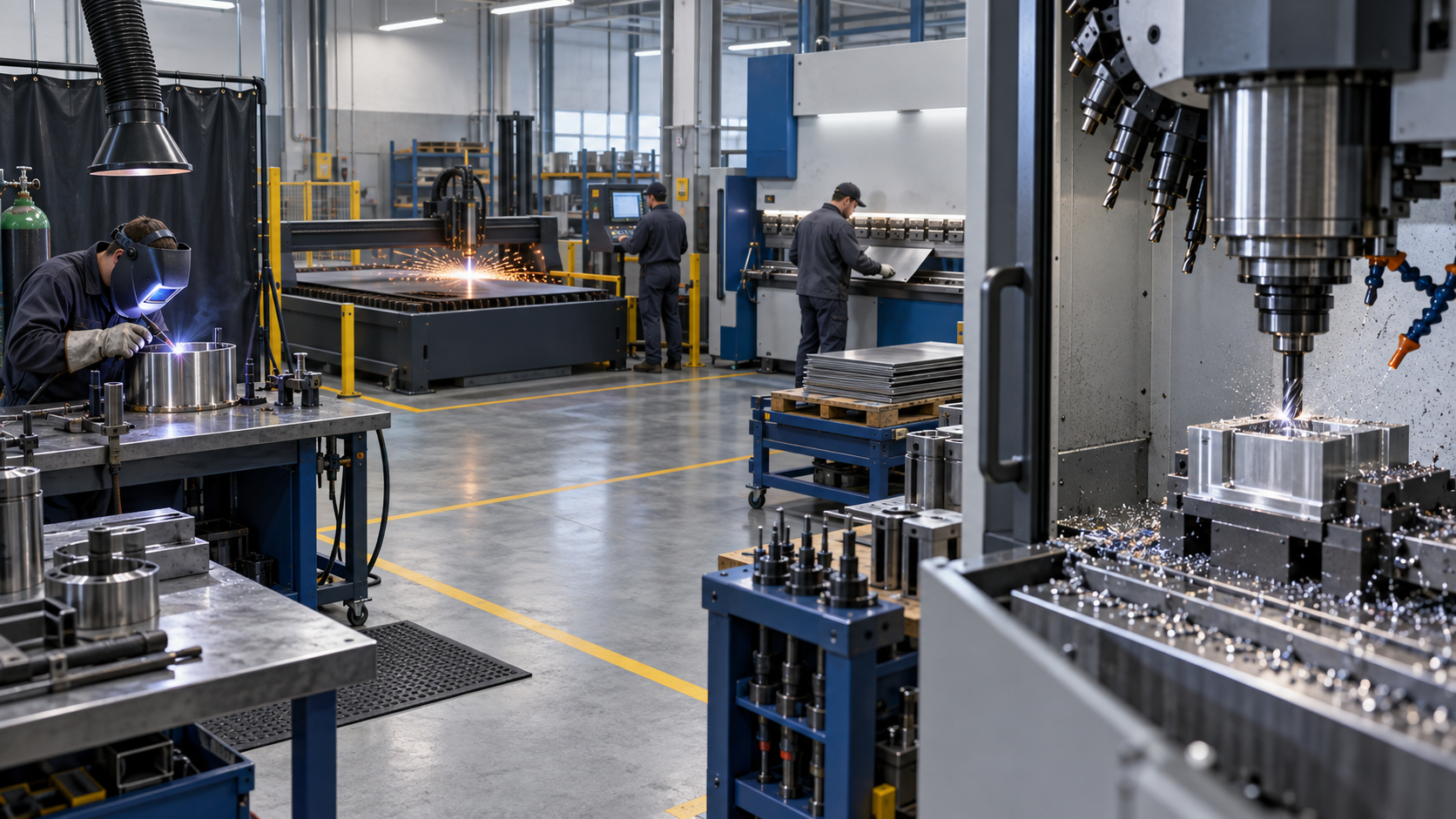
Classifying by application into five categories is far more useful than memorizing model numbers. When selecting a supplier, rather than asking "what equipment do you have," ask "which categories of equipment do you use for this type of custom part, and which operations are outsourced." The more outsourced steps, the harder it is to control lead time and the tolerance chain.
DFM up front: why cost and lead-time problems for custom parts mostly arise at the design stage
When quotes for custom parts come back high and lead times keep slipping, procurement and engineers often first react with "the shop didn't schedule production well." But flipping through rework records reveals that most overruns and delays do not originate at the machine tool, but at an earlier stage—insufficient consideration of manufacturing constraints at the design stage. A drawing that "can be drawn" in CAD does not mean it "can be made" in actual machining. Putting DFM (Design for Manufacturing) up front means moving such problems to be solved before quoting.
What DFM actually checks: three questions
Non-standard parts have no unified specifications, and manufacturing constraints vary by structure, so DFM is not a fixed checklist but revolves around a few recurring questions. Engineering typically looks at these three:
- Can the structure be machined with standard tooling? Deep narrow slots, internal right angles, fillets that are too small at the bottom, and positions where tools cannot reach will force EDM or special tooling, driving up cost and cycle time. Enlarging internal fillets to the range reachable by standard milling cutter radii often does not change function but can eliminate an operation.
- Do tolerances match functional requirements? Tightening the tolerances of an entire drawing uniformly to a high-precision range is the most common form of over-design. Usually only mating surfaces, locating surfaces, and critical functional dimensions truly need tight control; non-mating surfaces can use general tolerances. In the industry, strict tolerances can reach the ±0.005 mm level, but that is a range used on demand, not a default value.
- Is there over-design? Excessively thick walls, too many reinforcing ribs, and complex structures that insist on being one-piece all drive up material and labor hours. When sheet metal bending can replace milling from a solid block, or standard profiles can replace custom cross-sections, it is worth doing the math first.
What these three questions have in common is that they can all be changed at the drawing stage, and the changes usually do not affect function. Once discovered in the shop, changes become rework, drawing revisions, re-fixturing, and rescheduling.
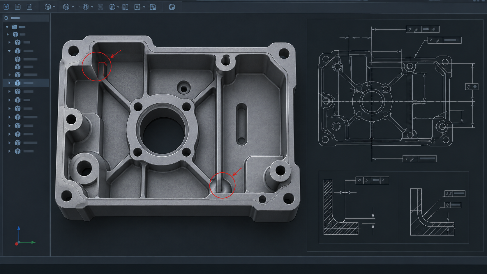
Avoiding pitfalls in custom parts: put DFM before quoting
Sequence is critical. Quoting first and doing DFM later is equivalent to negotiating price and lead time with a drawing that has not yet been optimized, and every subsequent change means starting over. A more robust approach is:
- After uploading CAD, run a round of DFM checks first, get manufacturability feedback, then proceed to formal quoting;
- Clearly mark critical functional dimensions and datums on the drawing, and give general tolerances for the rest, avoiding "tightening everything";
- Distinguish appearance surfaces from functional surfaces—appearance surfaces govern surface roughness and texture, functional surfaces govern dimensions and geometric tolerances; the two have different requirements and need not be tied to each other.
To sum up in one sentence: Problems that can be fixed on the drawing should not be left to be fixed in the shop. For custom parts, DFM is not an extra process, but a step that squeezes out uncertainty in cost and lead time in advance. With a drawing in hand, the next step is usually to run a round of DFM checks first, then discuss material, tolerances, and quantity.
From CAD to delivery: the online custom process for custom parts
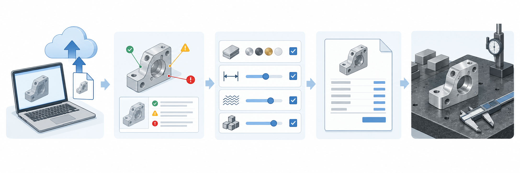
The online process for custom parts is essentially a line strung together by several fixed communication nodes: upload CAD files → get DFM feedback → verify details → quote → production and quality inspection. At each node, the clearer the boundaries of what the customer must reply and what the manufacturer must confirm, the fewer rounds of back-and-forth changes. Below, each node is broken down.
Uploading CAD and getting DFM: the starting point of the custom parts process
What customers upload is usually a set of files: a 3D model (STEP, IGES, or native format) plus a 2D engineering drawing. With only a 3D model, the manufacturer can judge geometry and rough machinability; information such as dimensional tolerances, geometric tolerances, surface roughness, and datums is almost exclusively written on the 2D drawing. Without the drawing, DFM feedback can often only stay at the level of "whether the structure is feasible," and precision requirements must be supplemented separately.
When DFM feedback returns to the customer, it usually points out three types of issues: walls that are too thin or deep cavities beyond the reach of standard tooling, tolerance callouts that do not match functional requirements, and structures that could be simplified but have been complicated. This step is the most cost-effective link in the entire custom parts process—the cost of changing a drawing is far lower than changing machine programs or scrapping already-machined parts.
Detail verification and quoting: material, tolerances, surface treatment, quantity
After DFM is approved, the next step is the pre-quote verification. There are usually four items the customer needs to confirm: material grade and condition (for example, 6061-T6 or 7075-T6, annealed or solution-treated and aged), key tolerance bands (which dimensions must be tight and which can be relaxed), surface treatment (anodizing, black oxide, sandblasting, plating, etc.), and quantity and batch. If any of these four changes, the price changes with it.
This stage is the most prone to back-and-forth changes. A common situation is: the drawing only specifies "tolerances per GB/T 1804-m," but the actual assembly requires tighter ones; or the surface treatment only says "anodizing" without specifying film thickness and color. The manufacturer can only quote based on conventional assumptions, and during production adjusts according to verbal additions from the customer. When the two sides' understandings differ, problems arise. Marking functional dimensions and cosmetic surfaces separately is far more effective than arguing over a general tolerance table.
Production and quality control: the gatekeeping before custom parts are delivered
Once production begins, there actually aren't many stages the customer can participate in, but there are several control points worth agreeing on in advance: whether the first article is submitted for inspection, which measuring instruments are used for key dimensions, and whether a report must accompany the shipment. In common industry practice, tight tolerances can reach the ±0.005mm level, but this falls in the high-precision range and not all structures can achieve it; it depends on the feature dimensions, material, and fixturing method. Documents such as full-dimension CMM reports, material certificates, and NDAs can usually be requested as needed, but you must ask in advance; requesting them afterward is often too late.
The advantage of the online process only becomes apparent here: files, DFM records, quote confirmations, and inspection data are all on the same chain, so if a problem arises it can be traced back to a specific stage. Custom part projects handled through back-and-forth offline emails are the most prone to disputes over "which version was being discussed at the time."
Quality inspection, packaging and shipping, and after-sales support: the last mile of custom parts
After the drawing is confirmed, the material is selected, and the machine stops, the custom part reaches the most easily overlooked stretch: how to prove it is qualified, how to ensure it reaches you intact, and how to trace back if a problem arises. If these three things are not arranged well, the time and cost saved earlier will all be paid back here.
Inspection methods: first article, sampling, and measurement means
For custom parts in mass or small-batch production, a first article inspection is usually performed first—the first piece is checked item by item against the drawing to confirm that dimensions, geometric tolerances, and surface roughness are all within range, and only then is subsequent machining released. If the first article fails, everything after it is scrap. Once batch production is stable, it shifts to sampling inspection; the sampling ratio and acceptance rules should be written into the order, not agreed verbally.
The measurement means depend on the type of dimension. For geometric quantities such as profiles, hole diameters, and position tolerances, coordinate measuring machines (CMM) or vision measuring instruments are commonly used in the industry; surface roughness is measured with a roughness tester. A common industry practice is to include a self-inspection report with the shipment, and material certificates or third-party inspection reports can be requested when necessary. These are industry conventions that "can usually be requested"; the specific inspection items are subject to what you confirm with the manufacturer when placing the order. Do not assume every order comes with a full set of reports.
Packaging, rust prevention, and accompanying documents
Custom parts often have high unit value and low quantity, so one dent means one fewer part. Metal parts need rust prevention: inter-process rust prevention, drying after cleaning, and adding rust-preventive paper or VCI film; parts with mating surfaces or mirror finishes should be packaged separately to avoid rubbing against each other. Non-metal parts need protection against compression deformation and static electricity. It is best to specify the packaging method in the order, especially for cosmetic parts.
Accompanying documents generally include a delivery note and a self-inspection report; if traceability is required, you can request material certificates, heat treatment records, and inspection reports. If the documents are incomplete, they must be supplemented at acceptance, and the supplementation process drags on for another day.
After-sales traceability: won't assemble, dimensional drift, batch inconsistency
The most common after-sales problems with custom parts fall into three categories. Won't assemble: most likely the mating dimensions or geometric tolerances are out of tolerance, or the drawing datum and the actual assembly datum are inconsistent. Dimensional drift: dimensions of parts in the same batch gradually deviate from front to back, usually pointing to tool wear, fixturing deformation, or release of internal stress in the material. Batch inconsistency: a material batch or outsourced process was changed, and as a result the two batches won't fit together.
The prerequisite for traceability is records: drawing version, material heat/batch number, machining parameters, and inspection data. Without these, you can only guess. Therefore, writing acceptance criteria into the drawing and order is far cheaper than arguing afterward. The last mile of custom parts is essentially about nailing down the definition of "qualified" in advance, rather than waiting until a problem arises to argue about whose responsibility it is.
Frequently asked questions
The questions below are the ones most likely to trip you up after reading the preceding text. The answers try to give the basis for judgment rather than empty talk.
How exactly do custom parts and standard parts differ? Which approach should I use for procurement?
Standard parts are commonly used parts whose structure, dimensions, drawing conventions, and markings are fully standardized and which are mass-produced by specialized manufacturers, such as threaded fasteners and rolling bearings. Custom parts (non-standard parts) have no unified national standard specifications; they are customized according to your drawings or requirements and are independently controlled by the manufacturing enterprise. When procuring, first ask yourself: can this part be replaced by an off-the-shelf standard part? If it can, you save the entire chain of drawings, DFM, and first article confirmation; if it cannot, then follow the non-standard process.
Why are quotes and lead times for custom parts generally higher than for standard parts?
Non-standard parts involve complex processes and high variability. Metal parts often require full-process quality control from blank to finish machining, with drawing analysis, fixturing plans, post-processing, and inspection in between. These steps have already been solidified and amortized in standard parts, but in custom parts every single piece must go through them again. So being expensive and slow is not the manufacturer being difficult; it is determined by the chain itself. To compress it, the main lever is front-loading DFM to reduce drawing changes and rework, not squeezing the unit price.
Before I send out a drawing, what can I check myself first?
At minimum, confirm four things: whether the key functional dimensions are clearly marked, whether the tolerances match the assembly function, whether the datum and geometric tolerances are clear, and whether cosmetic surfaces and functional surfaces are distinguished. Then think one level further: can this structure be machined to spec with standard tooling, and is there any obvious over-design? The DFM check mentioned earlier is essentially asking these questions on your behalf in advance. The more complete the drawing information, the fewer back-and-forth revisions.
What level of precision and inspection can custom parts generally achieve?
The commonly seen high-precision range in the industry can reach the ±0.005mm level, and examples of CNC equipment capability itself are cited as down to 0.0025mm, but these all depend on the material, structure, fixturing, and inspection means, and are not unconditionally achievable. For inspection, first article, sampling, CMM or vision measurement, and roughness testers are all common practices, and inspection reports and material certificates can usually be requested. The specific level achievable must be written clearly as acceptance criteria on the drawing and confirmed item by item with the manufacturer.
For small-batch custom parts, should I choose CNC, 3D printing, or sheet metal?
It depends on the shape and purpose of the part: for parts with rotational features or complex cavities that need metal strength and precision, go with CNC; for complex structures that need rapid assembly verification, 3D printing is more cost-effective; for plate-type, enclosure, and bracket parts, sheet metal bending and welding is usually more economical. Hand-made prototype duplication molds are suitable for appearance verification and small-batch replication. There is no single answer for selection; the key is to first clarify the functional requirements and quantity, then let the manufacturer advise based on process feasibility.
Key takeaways
- Custom parts (non-standard parts) are a concept relative to standard parts: they have no unified national standard specifications, are customized according to customer drawings or requirements, and are independently controlled by the enterprise; their cost and process complexity are usually higher than standard parts.
- The core of upfront preparation is drawing analysis—clarifying dimensions, shape, material, and tolerances, while also paying attention to structure, dimensional accuracy, geometric tolerances, and surface roughness.
- DFM front-loading can reduce later drawing changes, rework, and delivery risks: focus on checking standard tool accessibility, whether tolerances match function, and whether there is over-design.
- Grouping equipment by use makes it easier to remember: welding, cutting, forming, cutting (CNC machining centers can automatically change tools and perform multiple processes in one setup), post-processing, and inspection.
- Common high-precision ranges in the industry can reach the 0.0025mm level, with tight tolerances down to the ±0.005mm level, but this is a capability example, not a fixed promise from any one company, and must be confirmed one by one according to the drawing.



