Precision and Ultra-Precision Machining: First Establish a Precision Ladder Scale
When discussing precision and ultra-precision machining, first distinguish the levels, then discuss the process. The common industry tiers are as follows: general machining precision is about 10 μm (roughly corresponding to IT5~IT7), with surface roughness Ra 0.2~0.8 μm; precision machining tightens precision to 10~0.1 μm, with Ra below 0.1 μm; ultra-precision machining compresses the tolerance band to 0.1~0.01 μm, with Ra on the order of 0.001 μm. Put another way in finer terms: micron level 3~0.3 μm, Ra 0.3~0.03 μm; submicron level 0.3~0.03 μm, Ra 0.03~0.005 μm; nanoscale about 30 nm, with Ra better than 5 nm.
These are typical industry magnitudes, used to judge which tier a part should fall into, not the promised values of any particular factory. The difference is not in the process name, but in the required order of precision magnitude and surface roughness. Once a part enters the submicron or nanometer tier, the machine tool, cutting tool, measurement, and environment are no longer four independent options, but the same system.
Main Methods of Ultra-Precision Machining: Cutting, Grinding/Polishing, and Micro-Machining
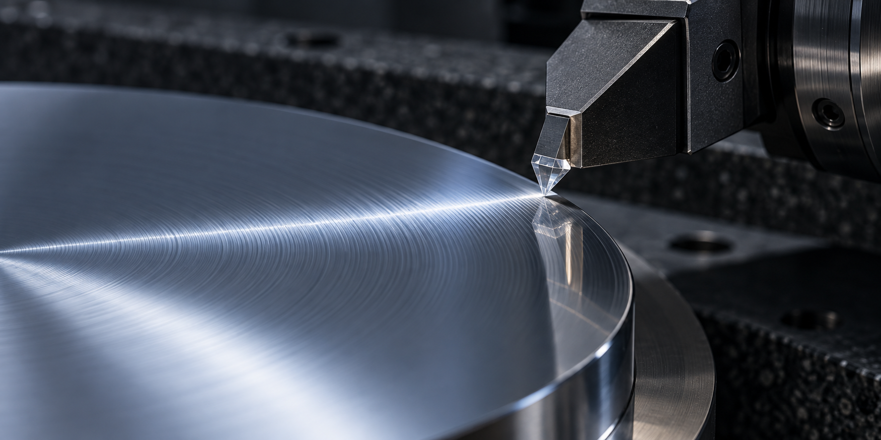
Ultra-precision machining is not a single process, but three parallel routes. The first is ultra-precision cutting: using single-crystal diamond tools for mirror turning or milling to directly cut optical-grade surfaces. The boundary is very clear—diamond has an affinity for iron-based materials, and tool wear is extremely fast when cutting iron-based alloys, so this method is mostly used for copper, aluminum, nickel-phosphorus plating, and some plastics; for cutting steel, cubic boron nitride or coated tools must be used instead, and surface quality drops by one tier.
The second is ultra-precision grinding, lapping, and polishing. Grinding is responsible for pushing materials that are hard and cannot be cut by diamond (cemented carbide, ceramics, hardened steel) to the submicron level; lapping and polishing are used to correct surface form and reduce roughness, for example the final Ra of optical mirrors is often finished by polishing. The third is ultra-precision micro-machining—electron beam, ion beam, laser beam, and LIGA processes. They do not rely on tools to remove material, but use energy beams or electrochemical methods for etching, suitable for microstructures, micro-holes, and nanoscale patterns.
Which route to choose depends first on the material, then on form accuracy and Ra requirements. A common industry boundary is: for Ra above 0.1 μm, ordinary precision grinding or turning can cover it; only when 0.01 μm or even finer is required do diamond cutting or ultra-precision grinding/polishing become necessary. These magnitudes are typical industry values, and what can actually be achieved depends on the machine tool, cutting tool, fixturing, and measurement conditions. It is recommended to clearly mark the critical surfaces on the drawing and then confirm with the machining provider.
Engineering Characteristics of Ultra-Precision Machining: Why It Must Integrate Machining and Measurement
Ultra-precision machining is not about tuning ordinary machining to be finer, but the result of four engineering characteristics superimposed. Once the order of magnitude falls below 0.1 μm, any weak link in a single stage will directly consume the precision margin.
- The machining object is the precision component itself. For parts such as inertial navigation floats, laser mirrors, and servo valve spools, the dimension chain is short and stiffness is low, and clamping force alone can deform the workpiece beyond the tolerance band.
- Multidisciplinary integration. Machine tool rigidity, spindle rotation error, cutting edge quality, measurement uncertainty, and ambient temperature gradient must all converge simultaneously; if one is missing, it gets stuck at the submicron level and cannot go lower.
- Machining-measurement integration. In-situ or in-line measurement is a necessary condition. Once a part is removed and then measured, there is often no rework margin when it is out of tolerance—the alignment datum is gone, and the error introduced by re-clamping is greater than that of the cutting itself.
- Production automation and error compensation. Computer control is relied upon to correct thermal deformation and tool wear in real time; manual fine-tuning cannot keep up with nanoscale drift.
The second point is the most easily underestimated: the finished precision of ultra-precision machining is essentially determined by the weakest link among the four chains of machine tool, cutting tool, measurement, and environment. A common industry practice is to feed in-line measurement signals directly back to the control system for closed-loop compensation, rather than waiting until machining is complete for sampling inspection. Inspection methods such as 3D scanning are often used for cross-validation in reverse engineering and re-inspection stages, but they cannot replace in-situ measurement during the cutting process.
Which Parts Ultra-Precision Machining Supports: From Gyroscope Bearings to Aspheric Mirrors
The precision of ultra-precision machining must ultimately land on specific parts. The following typical parts are each tied to a verifiable precision metric, making it easier to benchmark against your own drawing requirements.
- Float and support of an inertial navigation air-bearing gyroscope: supported by an air film, the roundness and surface quality of the mating surfaces directly determine drift stability.
- Vacuum unlubricated bearings for satellite instruments: a common industry practice is to achieve raceway Ra on the order of about 1 nm, with roundness and cylindricity controlled at the nanometer level, to avoid lubricant volatilization contaminating the optical payload.
- Precision servo valve spool and sleeve: submicron-level mating clearance, with precision machining ensuring zero-position leakage and response consistency.
- Laser gyroscope mirror: flatness about 0.05 μm, Ra about 0.001 μm, reflectivity can reach the 99.99% level, directly affecting cavity loss and gyroscope sensitivity.
- Aspheric mirrors and semiconductor resin encapsulation molds: surface form error and surface roughness together determine imaging quality and encapsulation consistency.
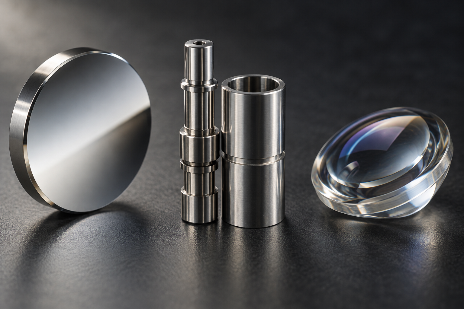
These parts together show that the value of ultra-precision machining is not in being "shinier," but in simultaneously controlling mating clearance, surface form error, and surface quality. If only one Ra is specified on a drawing, it is often insufficient to express the real requirement. Through the classic quote entry, you can first submit the drawing and let the engineering side confirm the critical dimensions and inspection methods.
From Theory to Production Line: Implementation Conditions and Enterprise Practices of Ultra-Precision Machining
Pushing precision to the submicron and nanometer levels cannot be done with just one good machine tool. Semiconductor resin encapsulation molds are a typical scenario: parts must be miniaturized and also consistent across multiple cavities. TOWA's approach is not to switch to a universal process, but to configure the three processes of cutting, grinding, and electrical discharge according to surface rules, controlling the height difference of each machined surface within 1 μm; using self-produced CBN end mills for cutting, surface roughness can reach Ra 5 nm, eliminating the uncontrollable manual polishing step; in a clean environment, using self-developed equipment for nanoscale fine machining, it can machine tens of thousands of pyramids about 6 μm high with 0.3 μm precision over a Φ220 mm area. This path shows that the production line capability of ultra-precision machining is the combined result of machine tools, cutting tools, measurement and control, and environmental control.
Four Supporting Conditions of Ultra-Precision Machining
- Machine tool: spindle rotation accuracy, guideway straightness, and thermal stability determine the upper precision limit.
- Cutting tool: the edge quality of diamond or CBN tools maps directly to surface roughness.
- Measurement and control: only in-situ inspection plus error compensation can close the loop and suppress deviation.
- Environmental control: constant temperature, thermal insulation, and cleanliness reduce thermal deformation and particle scratches.
If part accuracy falls in the micron or sub-micron range, first confirm the drawing tolerance band, material, and inspection method before discussing the process; the common industry practice is to review the drawing first, then determine equipment and unit price. You can refer to CNC machining capabilities, or go directly to classic quote to evaluate feasibility.
Common question: How do precision and ultra-precision machining get implemented
The following questions all revolve around the accuracy ladder and implementation conditions discussed earlier, making it easier for you to judge against your own drawings.
Should my part be quoted as precision machining or ultra-precision machining?
First look at which tier the tolerance band and surface roughness fall into, rather than starting with the process name. Common industry magnitudes are: general machining accuracy about 10μm, Ra 0.2~0.8μm; precision machining about 10~0.1μm, Ra<0.1μm; ultra-precision machining tolerance 0.1~0.01μm, Ra on the order of 0.001μm. These are typical industry ranges, not any company's guaranteed values. If your critical dimensions fall below sub-micron and you also require mirror-grade Ra, you should evaluate equipment, tooling, inspection, and environment along the ultra-precision machining path, rather than placing an order as ordinary finishing.
Why must ultra-precision machining use in-situ inspection?
Because the rework allowance for ultra-precision parts is often already close to zero. After removing the workpiece and putting it on a CMM or profilometer, if out-of-tolerance is measured, it is usually no longer possible to recover it by taking another cut, and the release of clamping stress may also cause dimensions to continue drifting. In-situ or in-line inspection can read the error in real time in the machine tool coordinate system, and with error compensation, another cut can be made. This is also why the article lists "integrated machining and inspection" separately as an engineering feature—it, along with the machine tool, tooling, and environment, is a link in the same system.
Can diamond mirror turning machine all materials?
No. Diamond tools undergo significant chemical wear with ferrous materials, and are usually used for aluminum, copper, oxygen-free copper, nickel-phosphorus plating, some plastics, and infrared crystals, etc. For mirror effects on steel parts, the more common industry approaches are ultra-precision grinding, lapping and polishing, or first plating with nickel-phosphorus and then turning. Before choosing a method, first confirm the compatibility of the material and tooling, and do not treat the process name as a master key.
What ensures the accuracy of ultra-precision machining?
It relies on system integration, not just a good machine tool. The four supports summarized in the article are: machine tool (spindle rotational accuracy, guideway straightness, thermal stability), tooling (edge quality and wear control), measurement and control (in-line inspection, error compensation), and environmental control (constant temperature, thermal insulation, cleanliness). If any link is a weak point, the final accuracy is held back by that link. In enterprise-level practice, configurations such as those for semiconductor packaging molds that combine cutting, grinding, and EDM to press the height difference of the machined surface below 1μm are also the result of this system working together.
If only Ra is marked on the drawing, is that enough to describe ultra-precision requirements?
Usually not enough. Ra only reflects the arithmetic mean deviation of the profile and does not constrain surface form, waviness, and local high points. For parts such as laser gyroscope mirrors, what really matters is a form metric such as flatness of 0.05μm; Ra 0.001μm is only one item among them. It is recommended to clearly write the form tolerance, waviness, datum, and inspection method together, and when necessary, agree on the inspection equipment and report format to avoid disagreements during acceptance.
Key takeaways
- The boundary between precision machining and ultra-precision machining lies in the order of precision magnitude and surface roughness, not in the process name
- Ultra-precision machining is a system integration of machine tool—cutting tool—measurement—environment, and a single weak link determines the upper limit
- In-line/in-situ measurement is a necessary condition for ultra-precision machining; once a part is removed and then measured, it is often already beyond rework
- Typical parts include gyroscope bearings, laser gyroscope mirrors, servo valve spools and sleeves, and aspheric mirrors
- The precision ranges in this article are common industry magnitudes; specific values vary with material, structure, and equipment



