
Why Extruder Screws and Barrels Wear When Output Declines Under the Same Formulation
Under the same formulation and screw speed, extruder output may gradually decline while melt pressure begins to fluctuate, leading operators to suspect screw wear first. However, changes in output cannot be directly equated with screw failure. Unstable feeding, a clogged screen pack, moisture in the raw material, abnormal temperature control, formulation changes, and gearbox or bearing problems can all produce similar symptoms. The correct approach is to first confirm process trends, then inspect the mating condition of the screw and barrel.
The screw and barrel operate together in an environment of high temperature, high pressure, high torque, friction, and corrosive gases. The screw performs conveying, melting, mixing, venting, compacting, and homogenizing, while the barrel provides the heated, pressure-bearing, and guiding working interface. As the screw flights wear, the screw's outside dimensions decrease; as the barrel inner surface or liner wears, the bore diameter increases. Both changes enlarge the working clearance, causing material to flow backward under pressure, reducing conveying efficiency and impairing plasticization stability.
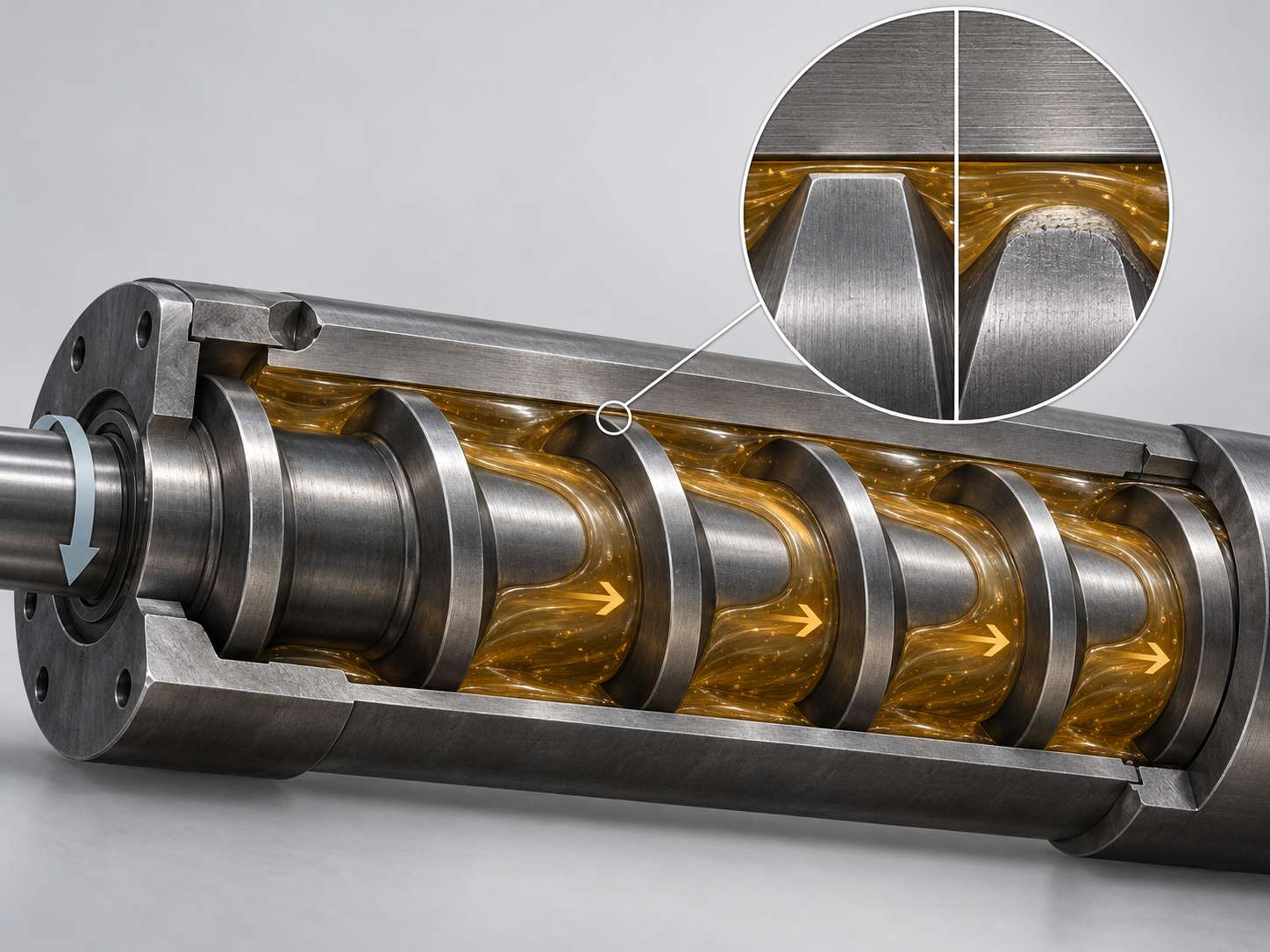
An Extruder Screw and Barrel Are Mating Components, Not Two Independent Wear Parts
Therefore, when evaluating extruder wear, do not measure only one outside diameter of the screw. Screw flights, barrel bore diameter, localized clearances, bending, concentricity, and assembly datums should be compared as one set of data. Intermeshing twin screws are also affected by separating forces and localized pressure, which may cause screw bending, localized barrel loading, or eccentric contact; in such cases, an “increased clearance” does not mean that only the screw has failed.
At the plant, first record changes in output, melt pressure, current or torque, melt temperature, and plasticization appearance, then inspect the flight edges, barrel inner wall, scoring, and abnormal material buildup after shutdown. Ultimately, the screw dimensions at critical cross-sections, barrel bore diameter, roundness, concentricity, and assembly clearance must still be measured. Rejection limits for different machines cannot be replaced with a single set of standard values; they should be based on the OEM drawings, equipment model, and an inspection specification approved by both parties. Some equipment commonly has a length-to-diameter ratio of approximately 15–30, but this is only structural background and cannot replace the dimensional requirements of the specific machine model.
From Process Signals to Dimensional Measurement: How to Diagnose Extruder Screw and Barrel Wear
When an extruder shows a gradual decline in output, fluctuating melt pressure, or uneven plasticization under the same formulation and screw speed, screw wear cannot be diagnosed directly. The working clearance between the screw and barrel may increase due to screw flight wear, barrel inner-wall wear, bending and eccentricity, or abnormal assembly alignment; unstable feeding, moisture in the raw material, a clogged screen pack, temperature-control failure, and gearbox or bearing problems can also produce similar signals.
First record the operating signals of the extruder screw and barrel
During operation, record output, melt pressure, current or torque, temperature in each zone, melt temperature, plasticization appearance, and abnormal noises simultaneously. If torque and pressure change synchronously, the issue may involve conveying resistance, the melting state, or localized contact. If output decreases while feed rate, temperature, and pressure controls remain normal, increased clearance becomes a more likely cause. Metal contamination, black specks, or abnormal particles indicate abrasive wear, scoring, or corrosion products; samples should be retained and the raw material batch traced.
Shutdown inspection and dimensional measurement should be completed separately
During disassembly inspection, first examine the flight edges, screw roots, barrel inner wall, and high-shear areas, and record scoring, pitting, localized bright contact marks, material buildup, and abnormal abrasive particles. Then measure the flight dimensions at critical screw cross-sections, barrel bore diameter, roundness, coaxiality, screw bending, and assembly clearance. The measurements must clearly specify the datum, cross-section, and instrument method; conclusions must not be based solely on a single-point clearance or visual appearance.
- Confirm the trend: Compare output, pressure, torque, and temperature records with those from normal batches.
- Collect evidence during shutdown: Photograph the screw flights, barrel inner wall, and contact marks, and retain samples of contaminants.
- Rule out external factors: Verify the feed rate, moisture content, screen pack, formulation, screw configuration, and condition of the drive components.
- Make a decision: Compare the dimensional report with the original manufacturer's drawings or an inspection specification approved by both parties to determine whether to replace a single component or evaluate the set as a whole.
It is particularly important to note that increased clearance does not mean that only the screw has failed. The screw and barrel are mating components; localized wear, bending, eccentricity, or abnormal coaxiality can all cause backflow and abnormal contact. There is no uniform rejection limit applicable to all machine models in the available information. The final determination should be based on the equipment drawings, the original manufacturer's technical specifications, and on-site measurement results.
Which areas of a twin-screw extruder are more prone to wear
A twin-screw extruder does not wear uniformly along the entire screw. The material condition, loading mode, and contact marks should be examined by area, including the feeding and conveying, melting and mixing, intermeshing high-shear, venting, and homogenizing and metering sections. Increased clearance does not mean that only the screw is damaged; barrel liner wear, screw bending, assembly eccentricity, and poor alignment can all cause localized contact.
Feeding and conveying section: abrasive wear caused by foreign matter and fillers
After glass fibers, mineral fillers, pigment agglomerates, or unmelted foreign matter enter the feed section, abrasive wear may develop between the screw flights and the barrel inner wall. This area also handles solids conveying and initial compaction. If feed fluctuates or foreign matter becomes trapped, scoring can easily occur at the flight edges, barrel inlet, and liner transition. Inspection should focus on localized scratches, metal chips, and changes in flight width rather than only the average dimensions of the entire screw.
Melting and mixing and intermeshing sections: combined high shear and separation forces
Shear, pressure, and temperature are generally higher in the melting and mixing sections. Material in an intermeshing twin-screw configuration generates separation forces on the screws, creating a tendency toward screw bending and increasing the possibility of localized pressure wear on the barrel. Smaller clearances promote shearing and mixing, but may also amplify temperature overshoot, torque fluctuations, and localized contact. If abnormal noises, unstable melt temperature, or pressure fluctuations occur, inspect the screw flights, barrel bore wall, axial movement, and assembly alignment at the same time.
Venting and homogenizing and metering sections: corrosion, backflow, and localized wear
The venting section may come into contact with halogen-containing or acidic substances, or volatiles generated by plastic degradation; the corrosion risk must be confirmed in conjunction with the formulation and temperature history. The homogenizing and metering section is more likely to exhibit insufficient pressure buildup, material backflow, or uneven plasticization, but these phenomena may also result from simultaneous wear of the screw and barrel. Maintenance decisions should correlate segmented process records with disassembled dimensions: first locate the abnormal area, then measure the flights, bore diameter, roundness, coaxiality, and assembly clearance. The replacement scope must not be determined solely from a single wear mark.
| Area | Primary risks | Priority checks |
|---|---|---|
| Feed conveying section | Abrasive wear from fillers and foreign particles | Inlet bushing, screw flight edges, and scratches |
| Melt mixing and intermeshing zone | High shear, separating forces, and localized contact | Intermeshing marks, bending, and alignment condition |
| Venting and homogenizing section | Corrosion, backflow, and unstable pressure | Bore wall, screw flight dimensions, corrosion spots, and clearances |
How to Select Materials for Extruder Screws and Barrels: Balancing Wear Resistance, Corrosion Resistance, and Toughness
The materials for extruder screws and barrels should not be selected based solely on hardness or material grade. First, identify the failure mechanism: glass fibers, mineral fillers, pigment agglomerates, and unmelted foreign particles may cause abrasive wear; materials containing halogens, acidic components, or degradation volatiles may increase the risk of corrosion; and high rotational speeds, high torque, small clearances, and localized material blockages place greater demands on torsional strength and toughness.
Extruder Screw Materials: First Determine Whether Wear Resistance or Impact Resistance Takes Priority
Alloy steel or nitrided steel can be considered for general operating conditions, with particular attention paid to base-material strength, torsional resistance, heat-treatment condition, and surface-hardened layer. For highly filled formulations, wear-resistant steel, highly wear-resistant alloys, or localized hardening solutions can be compared; however, higher hardness does not necessarily mean better overall performance and may result in reduced toughness, insufficient impact resistance, or increased machining difficulty. If the equipment is exposed to foreign-particle impact, frequent start-stop cycles, or changes in screw configuration loads, torsional resistance and toughness should be evaluated together with wear resistance.
Extruder Barrel Materials: Match the Bushing and Surface Treatment to the Material
Barrels can be evaluated by comparing integral alloy materials, nitriding, other surface-hardening methods, or bimetallic wear-resistant bushings according to the locations and severity of wear and corrosion. Bushing solutions make it easier to configure materials for high-wear areas, but the bond between the bushing and the base material, thermal expansion, bore diameter, roundness, and concentricity must be verified. When requesting material quotations, specify the material type, filler ratio, temperature history, rotational speed, torque, shear strength, and foreign-particle risk, and require the supplier to explain the recommended solution and its trade-offs. The final material grade, hardness, and hardened-layer requirements should be confirmed according to the equipment drawings, operating-condition data, and the supplier's traceable reports; they must not be specified directly without regard to the machine model.
| Abrasive wear caused by glass fibers and mineral fillers | Wear-resistant steel, wear-resistant alloys, localized hardening, or wear-resistant bushings | Wear resistance, base-material toughness, and inspection records for the hardened layer or bushing |
| Corrosive volatiles or material degradation | Corrosion-resistant alloy systems and compatible surface treatments | Corrosive environments, temperature history, surface treatment methods, and applicable limits |
| High torque, foreign-object impact, or frequent start-stop cycles | Base materials prioritized for toughness and torsional resistance | Impact risk, heat treatment condition, torsional strength, and machining quality |
Therefore, material selection for extruder spare parts should follow the sequence of “failure mechanism—operating loads—material properties—inspection records,” rather than selecting the highest hardness first and then working backward to determine the application scenario.
Extruder Screw and Barrel Spare Parts Acceptance Checklist: From Visual Similarity to Technical Traceability
Extruder screws and barrels should not be accepted solely because they are “similar in size and look like the original parts.” They are mating components, and the operating clearance, localized wear, bending, concentricity, and assembly orientation all affect backflow, plasticization, and abnormal contact. Procurement documents should first specify the equipment model, drawing revision, material formulation, filler ratio, temperature, rotational speed, and torque, and then define the material, machining, and inspection requirements.
Material and Treatment Records for Extruder Screws and Barrels
During acceptance, suppliers should be required to submit material certificates, along with records of heat treatment, nitriding, or other surface treatments. Hardness and hardened-layer inspections should specify the inspection location, method, and results; “high hardness” cannot replace specific records. For screws, the component sequence, rotation direction, end-face orientation, key or spline dimensions, and assembly markings should also be verified. The material grade must match the technical specifications approved by both parties and should not be replaced based solely on the supplier’s verbal recommendation.
Dimensional and Assembly Inspection of Extruder Spare Parts
| Acceptance item | Items to be verified |
|---|---|
| Screw | Outside diameter, critical flight dimensions, shaft end, key/spline, bending, and component sequence |
| Barrel | Bore diameter, roundness, concentricity, bushing fit, and assembly datum |
| Appearance | Galling, impact damage, cracks, burn marks, uncleared burrs, and corrosion protection condition |
| Documents and identification | Drawing revision, inspection report, packaging label, batch number, and factory photographs |
Before trial assembly, a twin-screw extruder must also be checked for the meshing relationship, direction of rotation, end-face orientation, and assembly clearances. An incorrect sequence or eccentric assembly may be mistaken for material failure. Existing information does not provide uniform wear thresholds, hardness requirements, or acceptance tolerances applicable to all models. Therefore, dimensions, roundness, concentricity, hardened-layer properties, and inspection methods should be implemented according to the original manufacturer's drawings, equipment technical specifications, or inspection standards approved by both parties. If complete records cannot be provided, Purchasing should suspend release for acceptance rather than accept the parts based solely on appearance.
What technical issues should Purchasing confirm with the supplier before replacing extruder spare parts?
A request for quotation should not simply state “machine according to the original part” or “provide wear-resistant screws.” Spare parts for extruder screws and barrels must correspond to the actual material, wear mechanism, assembly datums, and inspection methods. At a minimum, the purchasing documentation should specify the equipment model, screw diameter and configuration, material and filler ratio, operating temperature, speed, torque trend, and the wear locations and measurement records of the old parts. Without this information, it is difficult for the supplier to determine whether wear resistance, corrosion resistance, torsional strength, or toughness should be prioritized.
First confirm the wear mechanism associated with the material formulation
The first question to ask the supplier should be: Which failure mode is the recommended material or surface treatment intended to address? If the formulation contains glass fibers, mineral fillers, pigment agglomerates, or potentially unmelted foreign matter, require the supplier to explain the wear-resistant solution and the basis for its supporting data. If the material generates acidic, halogen-containing, or other corrosive volatile substances after decomposition, confirm how corrosion resistance will be verified. For high-shear, small-clearance, and high-torque operating conditions, also ask about the effects of increased material hardness on toughness, impact resistance, and machinability. The material grade should only serve as a candidate and should not be selected independently of the operating conditions.
Verify the screw and barrel configuration and the datums for critical dimensions
For a twin-screw extruder, the quotation should confirm the sequence of screw elements, direction of rotation, meshing relationship, end-face orientation, key or spline configuration, and the configuration of the feeding, mixing, venting, and homogenizing sections. Require the supplier to specify the measurement datums for critical dimensions such as screw outside diameter, flight dimensions, shaft bore, and barrel bore diameter, as well as the gauges or inspection methods used and how roundness, concentricity, bending, and assembly clearances are recorded. Do not accept a “qualified” conclusion without a drawing revision, datum definitions, and measurement locations.
| Confirmation item | Information to request from or confirm with the supplier |
|---|---|
| Material and treatment | Material certificates, heat-treatment records, nitriding or other surface-treatment records, and hardness and hardened-layer inspection results |
| Dimensions and assembly | Critical-dimension report, barrel bore diameter, roundness, concentricity, screw bending, keyways or splines, and assembly datums |
| Applicable operating conditions | Material, filler ratio, temperature, speed, torque, and the wear mechanism corresponding to the supplier's recommendations |
| Abnormality handling | Reinspection and handling procedures for assembly interference, localized contact, dimensional nonconformity, or missing reports |
Finally, the acceptance conditions should be included in the purchasing documentation: they must follow the equipment drawings, the original manufacturer's technical specifications, or inspection standards approved by both parties, rather than applying a generic hardness, clearance, or wear threshold. After receiving the spare parts, also verify the identification markings, element sequence, end-face orientation, and factory appearance photographs. If localized interference or contact marks are found before installation, stop assembly and recheck the condition of the screws, barrel, alignment, and bearings. The correct decision sequence is to first confirm the failure mechanism, then decide whether to replace individual parts or the complete set, and finally finalize the material, dimensions, and acceptance records.
Frequently asked questions about diagnosing wear on extruder screws and barrels
Whether an extruder screw and barrel need to be replaced cannot be determined solely by a decline in output or their appearance after removal. Operating trends, contact marks, critical dimensions, bending and concentricity, as well as abrasive-wear or corrosion mechanisms caused by the material, should be evaluated together. The following questions are suitable for maintenance reviews and spare-parts procurement discussions.
Can the screw alone be replaced after it has worn?
Possibly, but the barrel bore diameter, roundness, concentricity, and assembly clearance must be measured first. The screw should also be checked for bending, localized contact, and scoring on the barrel’s inner wall. If the barrel is already significantly worn or the two components are eccentrically fitted, replacing only the screw may still result in backflow, pressure fluctuations, or abnormal contact. Whether to replace them as a complete set should be determined based on the equipment drawings and measurement results.
How can you determine whether the barrel also needs to be replaced?
After shutdown, focus on checking localized wear, scoring, corrosion, and uneven contact on the barrel’s inner wall, then measure the bore diameter, roundness, and concentricity at critical cross-sections. If the wear is concentrated in the meshing zone or at a specific axial position, also investigate screw bending, assembly eccentricity, and bearing and support issues. The decision cannot be based solely on a single wear reading.
Is higher hardness always better for screws and barrels?
Not necessarily. When glass fiber, mineral fillers, or unmelted foreign matter are present in significant quantities, wear resistance may be more important; for materials containing corrosive volatiles, corrosion resistance must be considered. A high-hardness approach may also involve trade-offs in toughness, impact resistance, and machinability. Material selection should be based on the filler ratio, temperature, rotational speed, torque, and failure history, and should be confirmed after the supplier provides the relevant data.
How should spare-parts acceptance criteria be established when there is no uniform rejection limit?
Use the original manufacturer’s drawings, equipment model, and an inspection specification approved by both parties as the basis. Specify in advance the material certificates, heat-treatment or surface-treatment records, critical dimensions, hardness, hardened-layer characteristics, roundness, concentricity, element sequence, and inspection methods. Do not apply generic wear limits without verification. For twin-screw spare parts, also verify the direction of rotation, meshing relationship, end-face orientation, and assembly markings.
Key takeaways
- Declining output and pressure fluctuations can only serve as indications of wear; they must be evaluated together with shutdown inspection, measurement of critical cross-sections, and contact marks.
- The screw and barrel are mating components and should be evaluated together for clearance, localized wear, bending, concentricity, and assembly condition.
- Glass fibers, mineral fillers, and unmelted foreign matter tend to cause abrasive wear; corrosive volatiles, high temperatures, and high shear may alter the failure mechanism.
- Material selection should not focus solely on high hardness; trade-offs must be made among wear resistance, corrosion resistance, torsional strength, toughness, and impact resistance.
- Spare parts acceptance should require traceable records for materials, heat treatment or surface treatment, critical dimensions, hardness, concentricity, and the sequence of screw elements.



