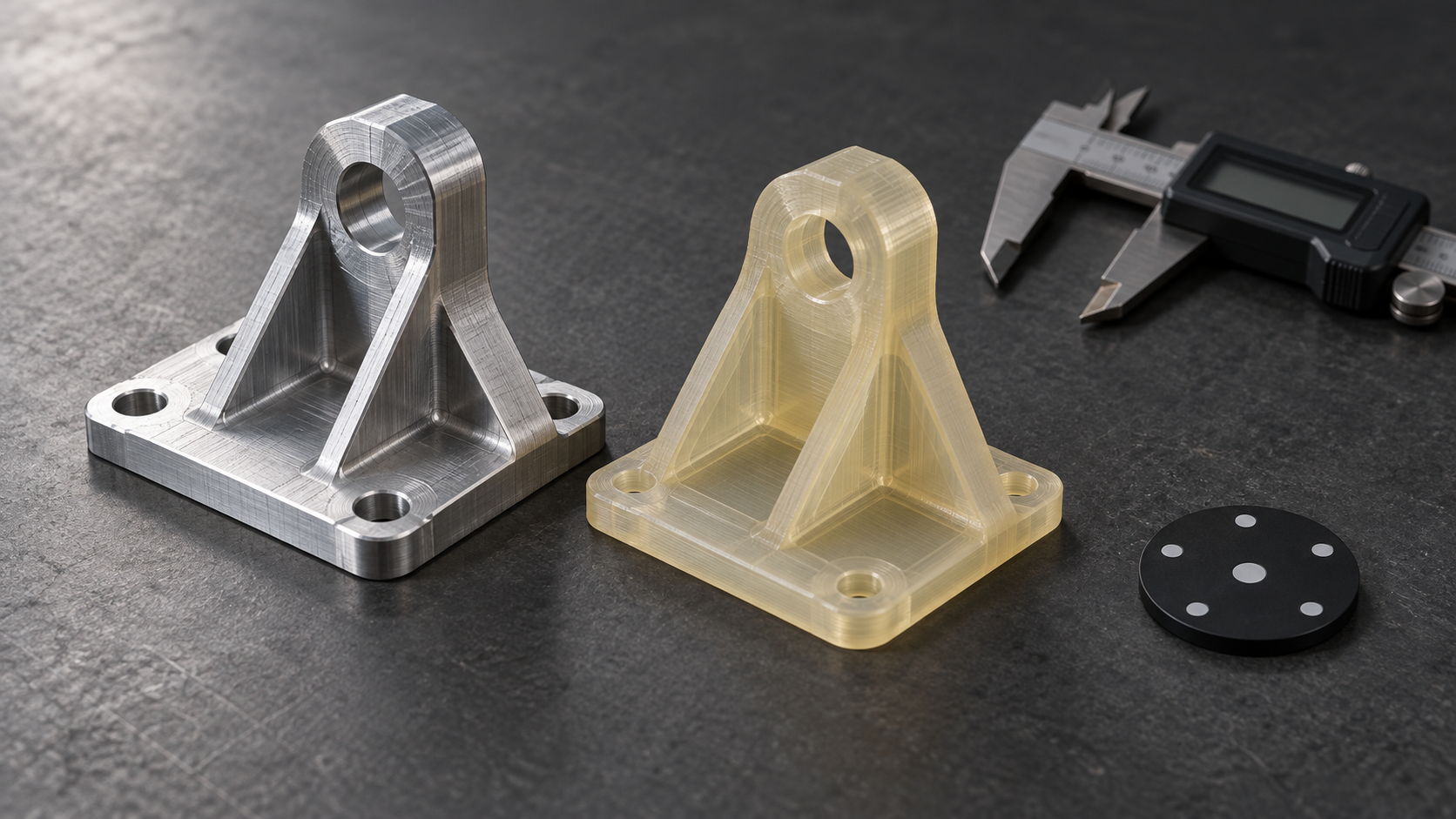
Starting from a prototype that failed to assemble once
On the trial-assembly bench, a snap-fit on a structural prototype broke. During review, assembly was smooth and the snap felt crisp; when it moved to injection molding, the first batch showed whitening at the snap root and hole positions offset by more than 0.3 mm on one side. Tracing back revealed three things: the prototype was made with an additive process, wall thickness was printed directly to the nominal drawing value, and the material stiffness differed from the mass-production plastic. The prototype was "made," but it did not validate where failure would actually occur.
This kind of problem is not an isolated case. The value of a prototype is not in "just making it and seeing," but in first thinking clearly about what needs to be validated—whether it is form proportion, assembly interference, structural stiffness, or demolding and mass-production feasibility. Different validation objectives lead to completely different choices of process, material, tolerance, and surface condition. Choose wrong, and the prototype gives a false positive: it assembles and flexes, but mass production gets stuck somewhere else.
The following expands on seven common misconceptions, each grounded in "what actually happens" and "what the alternative practice is." Criteria are written as much as possible as items that can be checked off on drawings and quotes, rather than as feelings.
Misconception 1: A prototype is just "make it and see," so pick any process
You often hear: it's just a prototype, as long as it assembles and looks fine, give it to whoever is fastest and cheapest. This holds for pure appearance review, but once the validation objective involves assembly force, snap rebound, or structural stiffness, it plants a landmine.
The value of a prototype is not in "making it," but in "what is validated." Write the validation criteria clearly first, then work backward to the process; reversing the order leads to rework.
| Appearance, proportion, feel | 3D printing (SLA/FDM) | Surface texture differs greatly from mass-production injection-molded parts; gloss review conclusions cannot be extrapolated |
| Mating dimensions, hole positions | CNC | Clamping deformation on thin-walled parts eats into tolerances; confirm the clamping plan with engineering |
| Structural stiffness, snap rebound | CNC (using material close to mass production) | Resin/PLA stiffness is low, leading to overly optimistic conclusions |
| Sheet metal bending and post-weld dimensions | Sheet metal | Bending springback and welding heat deformation must be reserved on the drawing |
| Small batch, appearance close to injection molding | Prototype duplication (vacuum casting) | The mechanical properties of the casting material still differ from injection-molded parts; use with caution for load-bearing parts |
| Mass-production part function confirmation | Injection molding (trial mold) | Long cycle and high cost; usually placed after the structure is frozen |
Alternative practice: state the "validation criteria for this run" on the drawing or RFQ. If the criterion is mating dimensions, choose CNC and clearly specify critical dimensions, datums, and inspection items; if the criterion is appearance and feel, 3D printing is faster, but note that the surface condition does not represent mass production. If the criterion is structural stiffness, use a material from the same family as mass production as much as possible, keep wall thickness at mass-production values, and do not thin it for printing convenience.
One more point: within the same prototype set, different parts can use different processes. The housing goes to 3D printing for appearance, the internal load-bearing bracket goes to CNC for stiffness, and the sheet metal base plate goes to sheet metal for hole positions—splitting criteria by part is more convenient than unifying the process for the whole set, and it leads to fewer misjudgments.
Misconception 2: Copying production drawing tolerances onto prototypes
The most common practice is: send the production drawing to the prototype shop unchanged, copying the tolerances as-is. The result is two things happening at once—the quote goes up, and the validation conclusions become less trustworthy. This is because prototype tolerances and production tolerances serve different purposes: prototype tolerances serve "what needs to be validated in this round," while production tolerances serve assembly function, gauges, and interchangeability. When both are written on the same drawing, the supplier can only quote to the tightest one.
Why problems arise: tolerances are criteria, not a precision performance
What the prototype stage really needs to answer is: do the hole positions line up, do the snaps engage, does the appearance review pass. Most of these criteria do not require ±0.05 mm. A common industry practice is to control key mating dimensions of prototypes at the ±0.1~±0.2 mm level, while non-critical appearance and non-mating surfaces are relaxed or even left untoleranced; production parts are then toleranced separately based on function, gauges, and process capability. This range is only a starting point for judgment; specific values must be confirmed with the supplier based on drawing function and must not be treated as guaranteed values.
Conversely, if ±0.02 mm is specified on a prototype, the supplier must either use a more expensive process (such as fine milling plus multiple setups) or play games with inspection—adding full CMM inspection to the quote, extending lead time, and doubling cost, while the assembly criteria you are validating remain unchanged. Worse, tight tolerances simply cannot be held reliably with low-stiffness processes (such as SLA resin, FDM), and the measured data becomes noise, leading to misjudgment during review that "there is a design problem."
| Symptoms | Common causes | Alternative approaches |
|---|---|---|
| Quotes are noticeably high and lead times are extended | Tolerances are specified as for production parts, so the supplier selects processes and inspection based on the tightest items | Specify tolerances in layers according to validation goals: tighten mating surfaces, relax non-mating surfaces |
| Measured dimensions show large scatter and cannot be judged | Tight tolerances are attempted with low-stiffness processes, so measurement noise exceeds the tolerance band | Switch processes (CNC) or change that dimension to a reference dimension |
| Prototype assembles, but production does not | The prototype tolerance band does not match production process capability, masking the true clearance | Predict clearance based on the typical capability of the production process for the prototype, and reserve adjustment allowance |
There is another easily overlooked point: the measurement datum for prototype tolerances and production tolerances is often different. A prototype may not have dedicated gauges, so dimensions are measured in the free state; production parts are measured after being located in a gauge. The numbers may be the same, but the meaning is different. During review, if only the numbers are compared, it is easy to reach the wrong conclusion. The approach is to note the measurement state on the drawing, or have the supplier clearly state the datum and clamping method in the report.
Misconception 3: Wall thickness, fillets, and draft "can be ignored at the prototype stage"
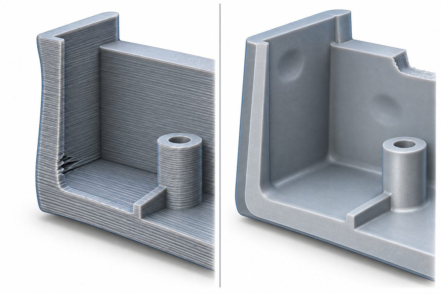
A commonly heard statement is: a prototype is just to make a shape first, and wall thickness, fillets, and draft can be changed before tooling. This assumption holds for pure appearance review, but once the prototype is used to validate structural strength or is later converted to injection molding, the cost appears. I once saw an enclosure prototype made by 3D printing, with wall thickness set to 1.2 mm according to the outer shape, and the assembly feel was normal; after conversion to injection molding, obvious sink marks appeared at the same location, and the snap roots fractured in batches due to insufficient weld line strength.
The problem is not 3D printing or injection molding itself, but that the forming logic of the two processes was mixed at the prototype stage. Additive manufacturing builds layer by layer, and the main risks of thin walls are warping and interlayer strength; injection molding involves melt filling plus cooling shrinkage, and the risks of thin walls are incomplete filling, sink marks, and weld lines. For the same thin-wall structure, the failure locations of the two processes often do not coincide.
Failure differences of thin walls under different processes
| Structural feature | Common behavior in additive manufacturing (FDM/SLA/SLS) | Common behavior in injection molding | Pre-embedded measures possible at the prototype stage |
|---|---|---|---|
| Wall thickness below mainstream empirical values (e.g., plastic parts less than 1 mm) | Thin-wall warping, interlayer delamination, more obvious on long edges | Incomplete filling, sink marks, low weld line strength | Build up critical wall thickness to a process-achievable range, or mark as a non-production-representative part |
| Internal fillet too small or missing | Printing is unaffected, but stress concentrates at sharp corners | Filling is difficult at sharp corners, prone to short shots and stress cracking | Pre-embed R corners at internal corners, prioritizing load-bearing locations |
| No draft angle | No effect on printing | Demolding scratches, ejector marks, surface haziness | Pre-embed 1°~2° along the demolding direction (common industry practice, confirm with drawings and supplier) |
Alternative approach: decide the degree of pre-embedding based on the verification goal
- To verify structural strength or transfer to injection molding: wall thickness, fillets, and draft should be pre-embedded according to mass production processes. For wall thickness, first take values from the common range for the material and process; for fillets, the load-bearing internal corners should be no less than 0.5 times the wall thickness; the draft angle should be reserved along the demolding direction.
- Only confirming appearance and assembly footprint: can be relaxed, but must be marked on the drawing as "non-mass-production representative part" to avoid later misuse.
- Non-load-bearing decorative parts: thin walls and no draft are acceptable, provided they do not participate in assembly positioning and do not bear repeated loads.
Myth Four: Assembly prototypes do not need datums
I have seen a batch of structural prototypes that snapped together smoothly during review and screws went in, leading to the conclusion "the structure is fine." After transfer to injection molding, in the first batch of 200 pieces, about 30% of the snaps jammed on the assembly line and 20% of the holes were misaligned. Investigation revealed: the prototypes were SLA printed, with no unified datum plane, each part was formed independently in its own orientation, and alignment during assembly relied on feel. The parts themselves were all within tolerance, but there was no common positioning reference between parts—the problem was not that they were made inaccurately, but that "accurate" had never been defined.
The core task of assembly prototypes is not to reproduce part shapes, but to reproduce the positioning relationships between parts. Without datums, successful assembly is just a coincidence, and if assembly fails, it is impossible to determine which face of which part is the problem. Once such problems are deferred to the mold stage, the cost and lead time of mold modification are far higher than adding a positioning post at the prototype stage.
Four datums to define before starting assembly prototypes
- Datum plane (A surface): choose the plane that contacts first during assembly, has the largest area, and is easiest to measure, and mark it on the drawing as the primary datum. At the prototype stage, this surface should be machined or printed accurately, rather than casually choosing a molding surface.
- Positioning post / positioning hole: at least one pair between two parts, with a diametral fit clearance of 0.05~0.15 mm (common industry practice, confirm specific values according to drawings and assembly method). If the positioning post is missing on the prototype, assembly can only rely on edge alignment, and deviations cannot be reproduced.
- Hole position relationships: the positions of screw holes and connector openings relative to the datum plane are more critical than the hole diameters themselves. If the hole diameter is too large, it can be fixed; if the hole position is off, the entire plate is scrapped.
- Fit clearance: the clearance values for moving parts, snaps, and slide rails must be written into the prototype drawing. If not written, they default to the supplier's experience—how much you get depends on luck.
| Symptom | Actual cause | Alternative approach |
|---|---|---|
| Prototype assembles, mass production does not | Prototype has no unified datum, relies on manual alignment | Mark A/B/C datums on the drawing, machine the prototype according to the datums |
| Snaps jam or are too loose | Fit clearance is undefined, supplier takes values based on experience | Specify clearance values and tolerance zones on the drawing |
| Hole misalignment | Hole positions are not marked relative to the datum, each part is formed independently | Mark hole positions with position tolerance using the datum plane as the origin |
| Flatness out of tolerance after assembly | Datum plane is not machined, printed surface is directly used as the assembly surface | Leave machining allowance on the datum plane or mill it flat after printing |
If the prototype has already been completed and missing datums are discovered, 3D scanning can be used for datum verification: scan the overall point cloud after assembly and compare it with the theoretical model to see which direction is off and by how much. But this is after-the-fact remediation—scanning tells you it is off, not which way to adjust. Marking the datums on the next drawing is more useful than scanning ten times.
Misconception 5: Surface treatment is just about "looking good"
A common saying is: leave the prototype untreated for now, as long as it fits; decide the surface after mass production. In reality, it's often this very step that causes a breakdown at the review meeting. Sandblasting, anodizing, painting, and electroplating all either remove or add a layer of dimension; and texture and gloss directly determine the customer's judgment of "feel" and "grade"—for the same structure, matte and glossy finishes may lead to opposite conclusions at the review meeting.
The surface layer changes dimensions, not just color
Anodized film thickness in the industry is commonly on the order of a few micrometers to twenty-some micrometers, with hard anodizing being thicker; painting is commonly 20–60 μm per side, and powder coating is thicker still. For mating surfaces, screw holes, and sliding pairs, these thicknesses are not negligible. If you make the prototype to bare-part dimensions and then anodize it, the holes become too small and the shafts too tight. A workable approach is: annotate mating dimensions on the drawing with an "before/after anodizing" datum, or apply masking to mating surfaces so that surface treatment does not fall on the mating area.
Choose the surface state based on the review objective, not on aesthetics
| Review objective | Recommended surface state | Things to note |
|---|---|---|
| Structure/assembly verification | Bare part or deburred only, mating surfaces masked | Any coating will change the fit clearance; verify dimensions first |
| Feel and grip review | Sandblasted or spray-coated samples with the corresponding texture | Texture number and grit size must be written into the requirements, otherwise the feel will vary from batch to batch |
| Appearance/CMF review | Color-matched spray coating or anodized color swatch comparison | Prototype color deviation cannot represent mass-production color deviation; a separate color swatch confirmation is needed |
| Wear-resistant/functional surface | Trial simultaneously with small samples using the same process as mass production | When the prototype process differs from the mass-production process, conclusions cannot be directly extrapolated |
Alternative approaches can be summed up in one rule: first clarify what this review is meant to examine, then decide how far to take the surface treatment. If examining assembly, keep surface treatment away from mating surfaces; if examining feel, fix the texture parameters and retain samples; if examining appearance, acknowledge that the prototype can only indicate direction, and mass-production color and texture must be confirmed separately. Writing this into the prototype technical requirements is far less troublesome than arguing about "the color is wrong" after the fact.
Prototype acceptance: what to inspect, what to inspect with, and how to write the criteria
Once the prototype is finished, no one at the review meeting can clearly say whether it "counts as qualified." Appearance parts look acceptable, assembly parts won't fit, and the dimensional report doesn't match the drawing—disputes often lie not in machining quality but in unclear acceptance criteria. The acceptance logic for prototypes differs from mass production: mass production inspects function and consistency, while prototype inspection is about whether "the specific issue to be verified this time has been verified." So first define the acceptance objective, then define the inspection items and methods, and only then move on to the quotation.
Comparison of acceptance items and inspection methods
| Acceptance item | Common methods | Applicable scenarios | Notes |
|---|---|---|---|
| Key external dimensions | Calipers, micrometers, plug gauges | Single parts, regular geometry | The measurement datum must match the drawing datum; caliper readings are for reference, and disputed dimensions should be re-measured with a CMM |
| Hole positions, fit clearance | Plug gauges, pin gauges, CMM | Assembly-type prototypes | Use pin gauges for quick screening of hole position deviation; if out of tolerance, use a CMM for positioning |
| Geometric tolerances (flatness, coaxiality) | CMM, surface plate + dial indicator | Parts with assembly or motion relationships | At the prototype stage, usually only the items affecting assembly are inspected; there is no need to replicate the full production drawing item by item |
| Complex curved surfaces, free-form shapes | Optical scanning (3D scanning) | Appearance parts, reverse comparison | Scanning gives a point cloud deviation color map; the criteria must clearly state whether it is compared against CAD or against the physical object |
| Function and feel | Assembly testing, functional testing | Structural parts, human-machine interaction parts | Base it on actual measured assembly results, not just dimensional reports |
Full inspection or sampling inspection
Prototypes usually come in only one or two pieces, so discussing full inspection versus sampling inspection is not very meaningful, but the rules must be stated clearly in advance: full inspection of key dimensions affecting assembly and function, checked piece by piece with calipers/plug gauges; non-critical appearance surfaces and decorative dimensions can be sampled or visually inspected. For vacuum casting (prototype duplication) in small batches, the first article must undergo full inspection, and subsequent parts are sampled on key dimensions, because silicone molds wear with the number of pours and dimensions drift.
How to write the criteria, in one sentence: write only the dimensions and conditions related to "what is to be verified this time," and mark the rest as reference or not required. Using a production drawing directly as a prototype acceptance drawing will bring a large number of irrelevant tolerances into inspection, which both increases cost and drowns the truly critical items in the report. When a datum needs to be reviewed or a reverse comparison needs to be made, the 3D scanning service can be used; to confirm the process and quotation scope, go through the online quote entry.
When these recommendations do not apply
The tolerances, draft, datums, and inspection requirements in the previous sections are based on the premise that "the prototype must bear part of the responsibility for the production part." If this premise does not hold, copying them blindly wastes money and time instead.
- Pure appearance/feel review parts: only evaluate color, texture, and parting line position; do not assemble or test. Key dimensions can be relaxed to the ±0.3 mm level or even looser, and draft angle and wall thickness uniformity do not need to be built in, but the drawing or work order must state "appearance confirmation part, dimensions not used as acceptance basis."
- One-time display parts: trade shows, bid prototypes, discarded after use. The most economical process and materials can be used, and there is no need to simulate production stiffness, but if the assembly relationships will be handled by the customer, mating hole positions are still recommended to be made to functional dimensions.
- Early concept parts with an unfrozen structure: at this point, changing the design is more important than controlling dimensions. Give tolerances based on "it can be assembled," and inspect only functional assembly, not full-dimensional reports.
- Extremely small-batch trial sales: within a few dozen pieces, vacuum casting or small-batch CNC is sufficient; there is no need to open a steel mold for it, and it should not be used to verify injection molding warpage and sink marks—those are production process issues.
One-sentence criterion: if the question this prototype needs to answer involves only "does it look right," make it as an appearance part; once it involves "it can be assembled, it can withstand use, it can be mass-produced," the previous rules cannot be omitted. When unsure, write the purpose into the inquiry form—it is cheaper than arguing afterward.
Frequently asked questions
The following questions are the ones most often asked repeatedly during the prototype quotation and acceptance stages. The answers are given according to engineering criteria, not sales talking points; where specific values are involved, the drawing annotations and supplier confirmation shall prevail.
Why can the same drawing differ several times over in prototype quotes?
Most differences are not in materials, but in three things: process route (CNC single-piece milling vs 3D printing vs duplication), tolerance and inspection requirements (whether a CMM full-dimensional report is required), and surface treatment (sandblasting, anodizing, and painting each have their own processes). Quoting the same part as an "appearance confirmation part" and as an "assembly verification part" involves different workloads to begin with. Writing the verification goal clearly at the inquiry stage is more effective than pressing for a lower price if you want comparable quotes.
Must prototypes be made to the same tolerances as production parts?
Not necessarily. Prototype tolerances serve the verification criteria: for verifying assembly and fit, key mating dimensions should be tightened; for verifying only appearance and feel, non-critical dimensions can be relaxed. A common industry practice is to control key prototype dimensions at the ±0.1~±0.2 mm level, relax non-critical dimensions, and then set production parts separately according to function. Specific values shall be based on the drawing and supplier confirmation; do not copy production tolerances directly onto the prototype drawing.
Should draft angle and wall thickness be reserved at the prototype stage?
It depends on the verification goal. If the prototype will later go to injection molding or vacuum casting, and demolding, sink marks, and filling need to be verified, then draft angle and wall thickness should be built in according to the production process; otherwise the prototype's "can assemble, looks good" is a false positive. If it is only a pure appearance review or a one-time display part, they can be omitted, but the drawing or handover sheet should be marked "non-production-representative part" to avoid downstream misinterpretation.
Do assembly prototypes need datums?
Yes. For prototypes lacking datum surfaces, locating posts, and hole-position datums, assembly problems are often postponed until mass production. It is recommended to specify datum surfaces, locating posts, key hole positions, and fit clearances on the drawing, and if necessary use 3D scanning to review the deviation between the actual part and the digital model. A prototype with unclear datums cannot be used as a basis for production release even if assembly is smooth.
Which items should be inspected in prototype acceptance, and should they be written in the quotation?
Yes. Common acceptance items include key dimensions, hole positions, fit clearances, appearance and surface condition, and functional assembly testing. Inspection methods are selected by item: calipers/plug gauges for conventional dimensions, CMM or optical scanning for form and position and complex contours, and functional assembly for verifying fit. Which are fully inspected and which are sampled should be agreed in the quotation or technical agreement; otherwise acceptance disputes will fall back on the supplier's default standards.
Key takeaways
- The primary purpose of a prototype determines the process: to validate assembly and structure, prioritize a route that can be formed at real wall thickness and real material stiffness; only when validating appearance and feel alone does a low-cost rapid process come into play.
- Do not copy mass-production tolerances onto a prototype. Prototype tolerances are written according to the "validation objective," while mass-production tolerances are written according to "assembly function." Mixing the two both drives up quotes and masks real problems.
- Wall thickness, fillets, and draft—these mass-production values must be built into the prototype in the mass-production direction from the start; changing one structural feature on a prototype usually means changing the mold, the inspection fixture, and the assembly jig together.
- Assembly-type prototypes must include datums: locating posts, datum surfaces, and hole positions done right the first time, otherwise the prototype assembles but mass production does not, and the problem gets deferred to the most expensive stage.
- Prototype acceptance must specify what is inspected, with what instrument, and what the criteria are; writing only "dimensions qualified" is as good as writing nothing. Optical scanning plus calipers/plug gauges for critical dimensions is usually sufficient.



