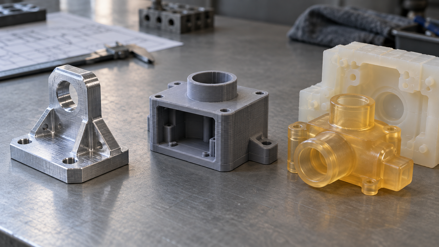
Rapid Prototyping: Define the Validation Goal First, Then the Process
When you get a part that needs a prototype, don't rush to compare prices or pick equipment. The first step in rapid prototyping is to clarify "what this part is going to be used for." Appearance reviews look at surface transitions, parting line locations, and surface color; assembly validation looks at hole positions, snap fits, and interference clearances; functional testing cares about material strength, temperature resistance, and dimensional retention after repeated assembly and disassembly. These three types of goals use completely different criteria for judging a process. Applying the same drawing to all paths often results in scrapping in the very first round.
Translate the validation goal into three actionable inputs: material (whether real engineering plastic or metal is needed), tolerance band (which dimensions must be tight and which can be relaxed), and surface requirements (whether texture, painting, or sanding is needed). Write these three into the RFQ, and the process boundaries will naturally emerge. Defaulting to the fastest or cheapest path usually just pushes the problem to the third round of revisions. Rapid prototyping saves revision time, not the need for judgment.
CNC Prototyping: Dimensionally Stable, but Watch Tool Reach and Fixturing
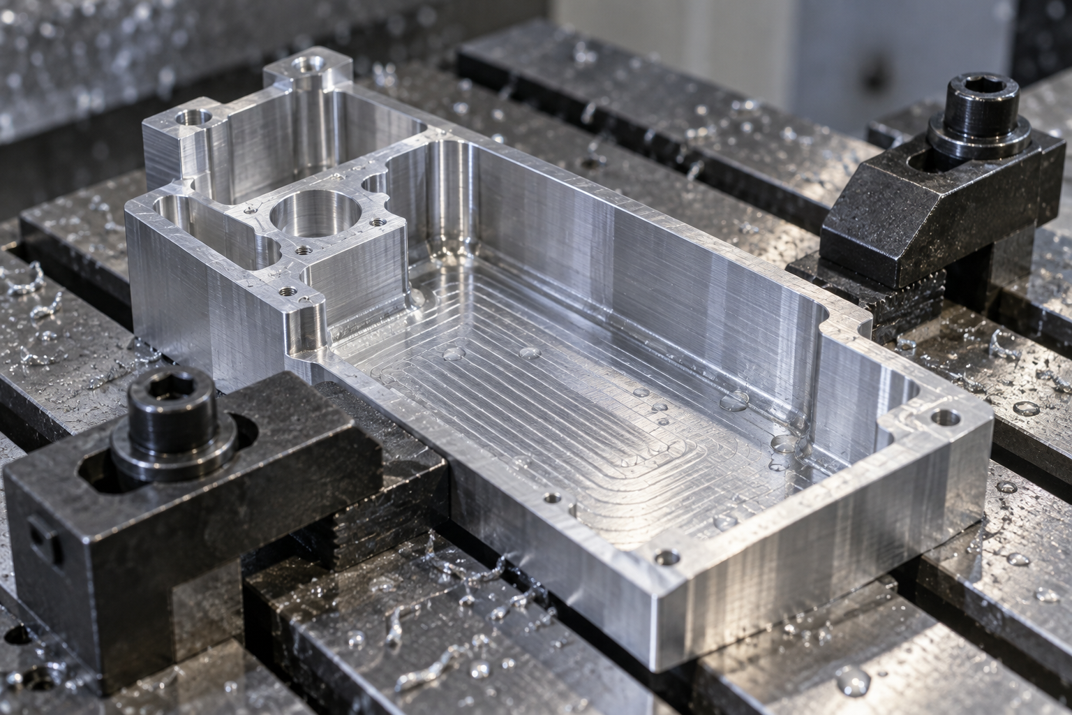
When you need real material, real threads, and mating parts that can actually be screwed together, CNC is usually the first choice in rapid prototyping. Aluminum, steel, POM, and PEEK can all go directly onto the machine, and dimensional stability and surface quality are closer to the final part than printed parts. The cost is hidden in the details: tool reach determines whether deep cavities and corner cleanup can be achieved, thin-walled parts deform as soon as they're clamped, and secondary fixturing compounds positioning errors.
How to Specify a Reasonable Tolerance Band
The general machining tolerance commonly seen in the industry is on the order of ±0.1 mm, and precision machining of mating surfaces and sealing surfaces can reach around ±0.02 mm; the exact achievable value depends on the material, feature size, and fixturing method. Confirm item by item against the drawing—don't tighten the entire drawing uniformly. At the rapid prototyping stage, there are often only a few critical dimensions that truly need to be controlled; relaxing the rest will noticeably change both the quote and the lead time.
Trade-offs Between Deep Cavities and Corner Cleanup
The longer and thinner the tool, the worse its rigidity, and vibration and tool deflection follow. When the cavity depth exceeds several times the tool diameter, you either switch to EDM or enlarge the corner radius so a standard cutter can enter. An internal corner specified as R0.5 on the drawing may actually have to be milled with an R1 or R2 cutter, or a process hole may simply be left. Communicating these changes early is easier than reworking afterward.
3D Printed Prototypes: Save on Tooling, but Accept Anisotropy
The greatest value of 3D printing in rapid prototyping is eliminating tooling: revisions only change the file, with no mold cost to amortize. The cost is anisotropy—the tensile strength of FDM parts between layers (Z direction) is usually noticeably lower than in the XY direction. The common industry saying is "about 70% or even less," but the exact factor depends on the material, infill rate, and toolpath, and must be confirmed by testing or supplier data. For parts under tension, bending, or repeated snap-fit disassembly, don't just order because the print orientation looks favorable.
SLA has a fine surface and suits appearance reviews, but resin parts creep under long-term load; SLS requires no supports and suits assembly interference validation, but its surface is powdery, and sealing surfaces often still need post-machining. For threads, it's recommended to directly mold coarse threads with a small diameter, or leave a pilot hole and tap afterward; fine threads are hard to guarantee for fit accuracy after printing.
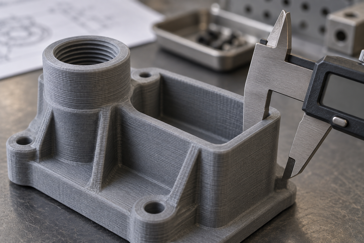
Three types of validation goals are not suitable for printed parts: sliding fit surfaces requiring precision mating, structural parts under sustained load, and inspection fixtures requiring long-term dimensional stability. For these goals, it's recommended to switch to CNC or sheet metal paths.
Vacuum Casting and Sheet Metal: Complementary Paths for Small Batches and Structural Parts
Rapid prototyping is often defaulted to "either CNC or 3D printing," but the other two paths are more cost-effective in specific scenarios.
Vacuum Casting: The Master Pattern Sets the Ceiling, Bubbles Determine Consistency
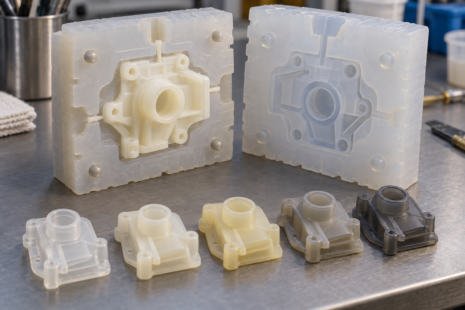
Vacuum casting (silicone mold duplication) suits small batches of 10 to a few dozen pieces where appearance and feel are close to injection-molded parts. The premise of duplicating with a silicone mold is master pattern quality—if the master pattern is SLA printed, layer lines will be copied onto every cast part; if the master pattern is CNC machined, its surface roughness directly determines the appearance of the duplicated parts. Bubble control during casting determines batch consistency: if vacuum degassing is insufficient, pores will appear inside the parts and show as white spots after sanding. The commonly seen shrinkage rate in the industry ranges from 0.1% to 0.5% depending on the material, and must be confirmed for the specific resin grade.
Sheet Metal: Springback and Welding Distortion Are the Main Sources of Allowance
Sheet metal suits structural parts such as enclosures, brackets, and mounting plates. Bending springback makes the actual angle smaller than the set value, usually requiring angle compensation in the tooling; welding distortion causes flatness to exceed tolerance, so process allowance can be left near the weld seam during design, or the datum surface can be machined after welding. If the distance from a hole to the bend edge is less than the material thickness, the hole will deform during bending, so pay attention during nesting.
Vacuum casting and sheet metal are not the mainstay processes of rapid prototyping, but choosing them correctly can save the cost of cutting a steel mold or avoid CNC hogging out thin-walled parts. For specific capability boundaries, refer to the rapid prototyping and sheet metal capabilities pages.
Cost-Driven Tolerances: Reserve Precision for Mating Surfaces
The cost of rapid prototyping does not change linearly with "part count"—what really drives up the unit price is tightening the tolerance band, upgrading surface roughness, and adding post-processing steps. For a Ø20 shaft, if ±0.02 mm is specified all around and Ra0.8 is required, the supplier will most likely need to add semi-finish turning, finish turning, or even grinding, and the unit price could be two to three times that after relaxing the tolerance. The common industry practice is: specify tight tolerances only on mating surfaces, sealing surfaces, and locating surfaces, and relax the remaining non-assembly areas to general tolerances (such as ±0.1 to ±0.3 mm, depending on material and size range, to be confirmed against the drawing).
Before requesting a quote, it's recommended to provide all information at once: quantity, material grade, critical dimensions and mating relationships, and whether there are appearance-part requirements. This information determines the process route and the number of fixturings; missing any one item can skew the quote. If you're not sure which surfaces should be tightened, you can directly upload the drawing through AI chat quoting and explain the assembly relationships, which usually converges faster than going back and forth revising the drawing.
Frequently asked questions
The following are high-frequency follow-up questions about choosing a rapid prototyping process. The answers all correspond to the criteria in the previous text and do not involve specific lead times or quotation commitments.
In rapid prototyping, how exactly do CNC and 3D printing divide the work?
It depends on the validation goal. For dimensional and mechanical criteria such as assembly interference, threaded fits, and sealing surfaces, prioritize CNC; the material is metal or engineering plastic, and the dimensions are more stable. If you are only doing appearance review, form confirmation, and rapid revisions, 3D printing saves on tooling and costs nothing to revise. The two are not substitutes for each other and often divide the work within the same project: print appearance parts, machine functional parts.
Why can't 3D printed parts be used directly as functional test parts?
The main obstacle is anisotropy. The Z-direction strength of FDM is noticeably lower than the XY direction, and layer lines and support removal marks can also affect mating surfaces. If the load direction in a functional test happens to fall between layers, the results will be distorted. For this type of validation, switch to CNC or vacuum-cast parts, or at least reassess after adjusting the print orientation.
How many parts is vacuum casting suitable for? How does it connect with injection molding?
In the industry, it is commonly used for small batches of 10 to a few dozen parts, with an appearance close to injection-molded parts, suitable for test marketing or small-batch validation. It uses silicone molds for reproduction, and master pattern quality and bubble control determine batch consistency. Only when the quantity is higher and the structure is finalized should you consider opening a steel mold and switching to injection molding; otherwise, the mold cost cannot be spread thin enough.
How should tolerances be marked on a drawing so they don't drive up cost?
Reserve tight tolerances only for mating surfaces, sealing surfaces, and locating surfaces, and leave the rest at general tolerances. Tightening all dimensions, increasing surface roughness requirements, and adding post-processing steps will all drive up the unit price. Before quoting, provide quantity, material, key dimensions, and assembly relationships so the supplier can give meaningful process recommendations.
When choosing a process for rapid prototyping, which step is most easily overlooked?
Inspection. A prototype must be measurable and verifiable once made, otherwise the validation goal is missed. Key dimensions should be marked on the drawing with the gauge or measurement method; sheet metal parts also need allowance reserved for bending springback and welding deformation. Defining the inspection plan together with the process is cheaper than reworking afterward.
Key takeaways
- Define the validation goal first: whether it's appearance, assembly interference, or functional durability determines the process, not the other way around.
- The tolerance band of a rapid prototype is determined jointly by the process and the fixturing. The more detailed the callouts on the drawing, the more important it is to confirm feasibility first.
- 3D printing saves on tooling but has pronounced anisotropy; CNC is dimensionally stable but requires considering tool reach and secondary fixturing.
- Vacuum casting suits small batches of 10 to a few dozen pieces, but master pattern quality and bubble control directly determine finished-part consistency.
- Cost-driven tolerances: reserving high precision only for mating surfaces can significantly lower the unit price of a prototype.



