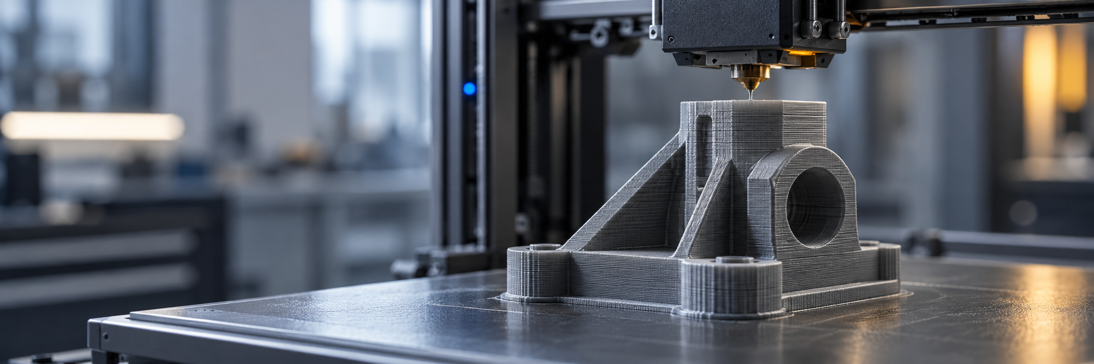
What Is 3D Printing: Which Machining Rules Layer-by-Layer Deposition Actually Changes
Start with a concrete scenario. A handheld device housing has three internal snap-fits, two screw bosses, and one USB opening. The engineer needs to confirm the assembly feel before cutting the mold. If the injection mold is cut directly, the mold cost and weeks of scheduling are all riding on a structure that has not yet been validated. If a complete shell is milled by CNC, tool accessibility at thin walls and undercuts forces structural changes. 3D printing offers a third path: build the 3D model into a solid layer by layer, so snap-fits, screw bosses, and internal cable channels come out in one forming step, unrestricted by draft direction and without compromising because the tool cannot reach inside.
So when answering "what is 3D printing," the key is not the encyclopedia definition of "it can print shapes," but which machining rules it changes. Traditional subtractive machining (CNC) cuts a part out of a solid block, so tool radius, fixturing direction, and deep-cavity accessibility exist before the design does. Molded forming (injection molding, sheet metal stamping) requires draft angles, uniform wall thickness, and a fixed punch direction. 3D printing is additive: material is deposited layer by layer along a controlled path, and geometric complexity no longer translates directly into machining difficulty. What this changes is forming freedom, batch economics, and the logic of material selection, not the upper limit of accuracy. The accuracy ceiling is still determined by the specific process, material, and post-processing, and cannot be promised in general terms.
Rule Differences Between Layer-by-Layer Deposition, Subtractive Machining, and Molded Forming
Layer-by-layer deposition brings three direct consequences. First, features "hidden inside" such as internal channels, lattice structures, and integrated hinges can be produced because they do not depend on tool entry. Second, unit cost is insensitive to batch size: the unit cost of part 1 and part 20 differs only marginally, which suits prototyping and trial production, but when scaled up, unit cost drops far less than with injection molding. Third, the bond between layers is an interface, so mechanical properties differ along the layer direction and perpendicular to it. This is the directional issue that must be handled in subsequent DFM. Understanding these three points is more practical than memorizing a string of process abbreviations.

Back to that housing. The point of printing a first version is to expose "design problems" such as assembly interference, snap-fit force, and screw boss positions in a few days at relatively low cost. Once the structure is frozen, then decide whether to continue with 3D printing for small batches, switch to CNC machining for stronger functional parts, or switch to injection molding for mass production. 3D printing is not the end process; it is a step that moves design validation and manufacturing decisions earlier. AGX can handle industrial additive manufacturing (FDM/SLA/SLS/MJF/DMLS), with the specific process tier matched to part requirements.
From 3D Modeling to Printable Data: How a 3D Model Becomes Machine-Readable Instructions
Printability Considerations at the 3D Modeling Stage
- Units: CAD templates commonly use millimeters, and STL export carries no units. If the other party reads it as inches, the part shrinks to 1/25.4. Stating the units in the filename or accompanying notes is cheaper than explaining later.
- Origin: Place the origin at the part's datum corner or assembly datum so you do not have to repeatedly guess orientation when arranging slices; multi-part nesting also will not misalign.
- Minimum feature: Bosses, ribs, and text smaller than the nozzle diameter or light spot can be drawn during modeling but will not come out when printed. Coarse-tune according to the process at the modeling stage.
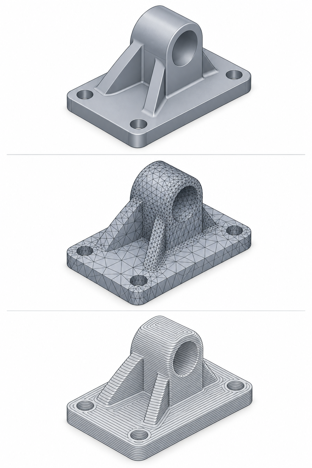
STL Mesh Accuracy: Too Coarse Leaves Chord Error on Curves, Too Fine Slows Slicing
How to Choose Between FDM, SLA, and SLS: 3D Printing Process Routes and Material Availability
When choosing a 3D printing process, the first cut should not be "which one has higher accuracy," but where the cosmetic surfaces are, which direction the load runs, and whether the structure can be supported. For the same drawing, moving the cosmetic surface from the top to the side may reverse the choice between FDM and SLA; moving the load from the XY plane to the Z direction also changes the trade-off between powder sintering and photopolymerization. Process routes are not ranked by price, but by constraints.
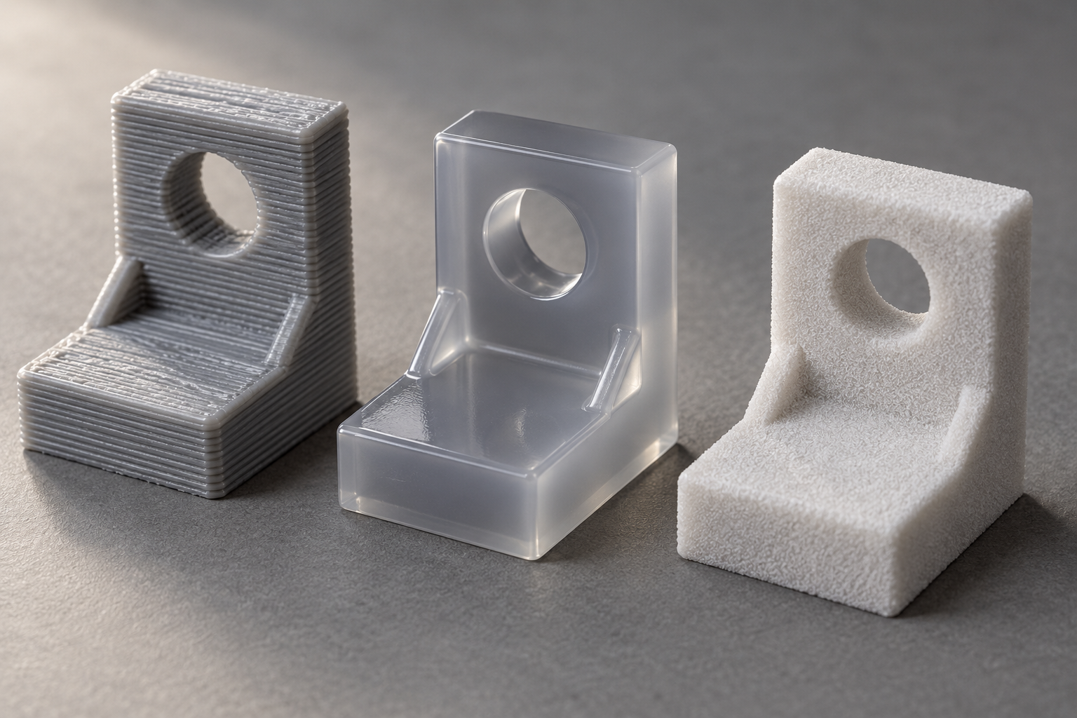
The following tiers the three mainstream routes: fused deposition modeling (FDM), photopolymerization (SLA/DLP), and powder bed (SLS/MJF). The range figures are only common industry references; the specific tier achievable must be confirmed with the supplier based on drawing features, material, and post-processing. AGX handles industrial additive manufacturing, covering FDM, SLA, SLS, MJF, and DMLS, but process capability is still governed by part geometry and material, with no accuracy promises.
FDM: Low Cost, Visible Layer Lines, and Anisotropy That Must Be Factored In First
FDM melts and extrudes thermoplastic filament and deposits it layer by layer. Its advantages are widespread equipment, inexpensive materials, and cost-friendly large parts; PLA, PETG, ABS, PC, and glass-filled nylon can all be printed. The price is visible layer lines and XY strength that is not on the same order as Z strength—a common industry statement is that Z-direction interlayer strength may be around half of XY strength, depending on material, layer height, and nozzle temperature. Therefore, for load-bearing parts on FDM, the primary load direction should be oriented within the XY plane first.
Suitable jobs: structural validation parts, prototypes of large housings, jigs and fixtures, and functional parts with non-cosmetic surfaces. Not suitable: fine cosmetic parts, thin walls with high detail, and load-bearing parts requiring isotropy. Overhangs beyond about 45° usually require supports, and support contact surfaces leave marks, so cosmetic surfaces should avoid support locations as much as possible.
SLA/DLP: Photocuring for fine cosmetic parts, dimensionally stable but vulnerable to long-term light exposure
SLA/DLP uses ultraviolet light to cure resin layer by layer. Layer thickness can be made very thin, the surface is fine, and detail reproduction is good, making it suitable for appearance review parts, fine structures, and small, highly detailed parts. Dimensional stability is usually better than FDM, but resin parts age and discolor under long-term UV exposure, and their mechanical properties tend to be brittle. Be cautious with structures subject to repeated stress, such as snap fits and claws.
Before choosing photocuring, ask two things: Will this part be exposed to outdoor or strong light for a long time? Will it be subjected to repeated stress? If the answer is yes, consider switching to engineering resin, switching to powder sintering, or changing the critical structure to CNC. For post-processing, sanding and blasting can remove support marks, and dyeing can unify the appearance, but these will slightly change dimensions, so allowance must be reserved on mating surfaces.
SLS/MJF: Powder bed without supports, the default option for functional parts and small batches
SLS and MJF are both powder bed processes. During forming, the surrounding powder naturally acts as support, so overhangs, internal cavities, and nested structures basically do not require dedicated supports; simply remove the powder after taking the part out. Strength anisotropy is smaller than FDM, making them suitable for functional validation parts, small-batch production, and complex assembly parts. Nylon (PA12, PA11) is a common material; adding glass fiber or carbon fiber improves rigidity and heat resistance.
The surface has a powder-grain feel, more uniform than FDM but not as fine as SLA. Powder removal from internal cavities and deep grooves may not be thorough, so avoid fully enclosed cavities and excessively narrow gaps in the design. Batch consistency is relatively stable in powder bed processes, which is also why they are often used for small-batch end-use parts.
Selection criteria checklist: rank by constraints, not by price
- Location of cosmetic surfaces: If the cosmetic surface is on the top or side and requires a fine finish, prioritize SLA; if the cosmetic surface can accept layer lines or graininess, both FDM and SLS can be used.
- Primary load-bearing direction: If the load is within the XY plane, FDM can be used; if the load crosses the Z direction, prioritize SLS/MJF or switch to CNC.
- Whether support-free structures are needed: For internal cavities, nesting, and deep overhangs, powder bed (SLS/MJF) is the least troublesome.
- Post-processing requirements: For sanding, blasting, dyeing, and vapor polishing, first confirm whether the process and material support them, and how post-processing affects dimensions.
- Material properties: When requirements for heat resistance, chemical resistance, toughness, flame retardancy, etc. exceed those of conventional resins and nylon, evaluate DMLS metal printing or switch to CNC.
- Batch trend: Additive manufacturing is reasonable for small-batch trial production, but once quantities rise, recalculate the per-piece cost and evaluate switching to injection molding or vacuum casting.
The three routes have no absolute advantages or disadvantages. FDM wins on cost and large parts, SLA wins on surface and detail, and SLS/MJF wins on support-free capability and functional strength. Rank the five constraints—cosmetic surfaces, load direction, support requirements, post-processing, and batch size—by priority, and the process route is basically determined. When unsure, provide the part drawing together with a load/appearance description to the supplier; this is far more useful than simply asking, "How accurate can you print?" AGX's 3D printing capabilities cover FDM/SLA/SLS/MJF/DMLS, and material availability and process matching can be confirmed together during the rapid prototyping stage.
Wall thickness, supports, and orientation: the three most failure-prone points in 3D printing DFM
Being able to draw it in modeling software does not mean it can be printed. In 3D printing DFM checks, what actually scraps a part is usually not insufficient precision, but three things: wall thickness too thin, supports not thought through, and orientation chosen arbitrarily. These three points are interconnected—changing wall thickness affects support contact surfaces, and changing orientation changes the load direction. Below, specific parts are used to break this down.
Wall thickness: whether it can be printed depends first on the thinnest point
Wall thickness is the first threshold in 3D printing DFM. The nozzle or laser beam has an actual diameter, and as material is stacked layer by layer, once it becomes thin enough it can no longer form a continuous solid: the common minimum stable wall thickness for FDM is on the order of 0.8–1.2 mm, SLA/DLP can be thinner, and SLS/MJF, because it relies on powder self-support, is actually less likely to collapse at thin walls. These are common industry reference ranges; the specifics depend on the process, material, nozzle or spot size, and the drawing callouts and confirmation with the printing factory shall prevail.
A more insidious problem than "cannot be printed" is warping. Thin walls cool quickly and shrink quickly, and large thin plates can warp at the edges, especially FDM ABS-type materials. The design countermeasure is not to thicken the wall excessively, but to keep wall thickness uniform: in transition zones that suddenly jump from 3 mm to 0.8 mm, stress concentrates, and both warping and delamination start there. A common approach for shell-type parts is to set the main wall at 1.5–2.5 mm and add local ribs to compensate for stiffness, rather than thickening the entire surface.
Supports: overhang angles, bridging, and contact surface marks
Fused deposition and photocuring both require supports to hold suspended structures. Powder sintering (SLS/MJF) relies on unsintered powder for self-support, but large flat undersides will still have a rough "powder surface." To judge whether supports are needed, look at two angles:
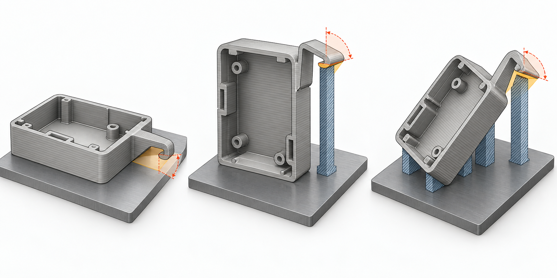
- Overhang angle: For surfaces inclined more than about 45° relative to the vertical direction, FDM usually requires supports, and beyond 60° they are basically mandatory. This is an empirical value; both material and layer thickness will shift this line.
- Bridging: For a span supported at both ends with the middle suspended, FDM can bridge short distances directly (a few millimeters to over ten millimeters); if too long, it sags. Bridging capability is related to the material's melt strength.
- Contact surface marks: Where supports contact the part, marks will definitely remain after removal. Cosmetic surfaces and mating surfaces should avoid support contact, or a 0.2–0.3 mm allowance should be left on the contact surface and ground off during post-processing.
A housing with a snap fit best illustrates the problem. The snap is a cantilever structure. If printed facing downward, the cantilever surface must either be supported or the angle changed; but if the snap root happens to be on a support contact surface, removing the support can easily break the snap or leave burrs. The DFM fix is: turn the snap into an inclined surface within 45° so it supports itself, or rotate the entire shell face where the snap is located so that the snap cantilever grows upward.
Orientation: layer direction determines strength, and Z is the weakest direction
3D-printed parts are not isotropic. In FDM, layers are bonded by fusion, and interlayer bond strength is significantly lower than in-layer strength; SLA has smaller interlayer differences but still has directionality; SLS/MJF is relatively uniform but still not omnidirectionally consistent like a forged part. This means orientation directly determines where the part is weakest.
The criterion is simple: the primary load-bearing direction should not fall in the Z direction (the stacking direction). Take that housing with a snap fit again—if the snap must withstand repeated insertion and removal bending force, it is best to have the long axis of the snap cantilever lie in the XY plane, with layer lines perpendicular to the load direction, so it is less likely to crack along layer boundaries when bent. Conversely, if the part is mainly under compression and the load direction is clear, align the load axis with the direction of highest in-layer strength.
Orientation also requires balancing support amount and surface quality. Laying it flat reduces supports, but critical faces facing down will have rough marks; standing it up gives smooth contact surfaces, but requires more supports and longer printing time. A common trade-off is: orient cosmetic surfaces and mating surfaces upward or away from supports, sacrificing non-critical surfaces. After changing orientation, go back and check wall thickness and overhang angles again; these three points usually require several rounds of adjustment to converge.
Tolerances and surface roughness: what level should be specified for 3D-printed parts
Look by tier: roughly what dimensional tolerance range each process falls into
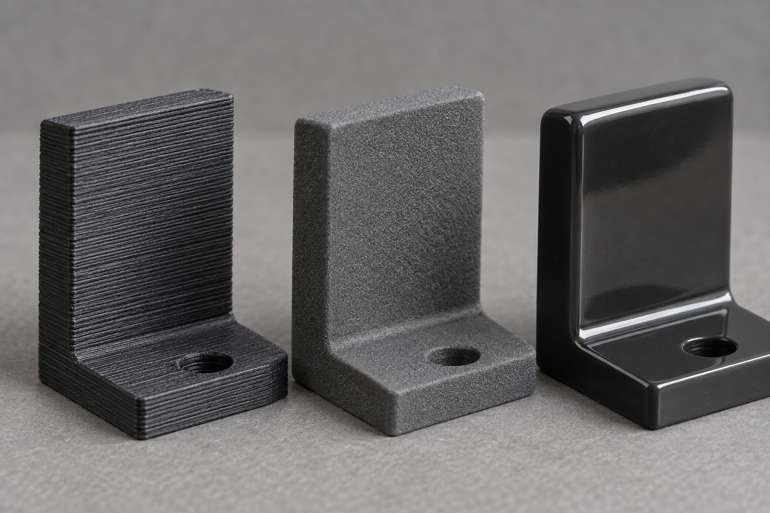
Surface roughness is not a single number: layer lines, post-processing, and process are bound together
- Sanding: manually or mechanically remove layer lines and lower Ra, but it will round edges and change local dimensions, so use with caution on precision parts.
- Bead blasting: unify surface texture and remove support residue, with little effect on dimensions; it is a common method for appearance parts.
- Dyeing / coloring: changes only appearance, not dimensions, suitable for prototype review parts.
- Vapor polishing: uses solvent vapor to melt and smooth the surface layer, and Ra can drop significantly, but thin walls and sharp corners will soften and deform, so wall thickness must be evaluated first.
- Annealing: improves interlayer bonding and internal stress, but may cause overall shrinkage, so dimensions must be reconfirmed.
Assembly, sealing, and threads: several types of features on printed parts that must be handled separately
After printing: post-processing, inspection, and common failure modes
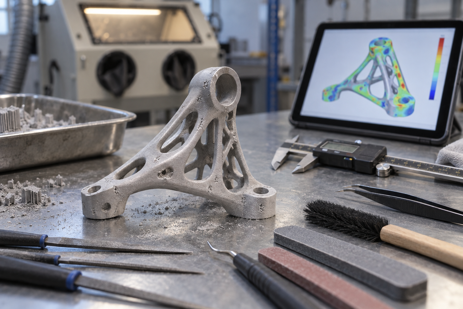
The moment a 3D printed part is taken out of the machine, its dimensions and appearance are not yet finalized. Support removal, sanding, bead blasting, coloring, and annealing—each step will affect the part; warping, interlayer cracking, and hole-position shift are also mostly exposed at this stage. Below, it is explained in three sections: post-processing, inspection, and failure modes, with a comparison table at the end.
How post-processing changes final dimensions and appearance
Support removal is the first step. Support contact surfaces will leave marks: the roughness of FDM support peel-off surfaces is noticeably higher than that of as-built surfaces, SLA support points will leave small bumps on the surface, and SLS is relatively clean but the support contact areas still have adhered powder. After support removal, sanding is usually required, and sanding removes a small amount of material—do not expect to recover tight profile tolerance on mating surfaces by sanding.
Bead blasting is used to even out the surface and is a standard method for appearance parts, but it will slightly chamfer sharp edges. Coloring and dyeing change only appearance, not dimensions. Annealing is an easily overlooked variable: annealing FDM parts can improve interlayer bonding strength, but it brings shrinkage and deformation, especially for thin walls and long cantilevers. If annealing is required, allowance and supports must be considered together at the drawing stage, rather than added after printing.
Inspection: what calipers, CMMs, and 3D scanning each handle
Inspection at the prototype stage is tiered according to precision requirements. For ordinary assembly verification, calipers and plug gauges are enough, measuring hole spacing, outer contours, and step heights. For critical dimensions such as mating surfaces and locating pin holes, a CMM can provide specific deviation values. For complex curved surfaces and freeform parts, using 3D scanning for full-dimensional comparison is more direct—overlaying the scan point cloud with the CAD model, the color deviation map shows at a glance where tolerances are exceeded, much faster than measuring point by point.
Inspection timing also matters. Printed parts are hygroscopic (especially nylon types), and dimensions will change slightly after a few days; to measure critical dimensions, it is best to measure as soon as possible after printing and after post-processing is completed, and to record environmental conditions. In the first article report, write the measurement datum, gauges, and environment clearly together, so that later batch comparisons are meaningful.
Five common failure modes: causes and countermeasures
Warping is mostly seen on large flat surfaces and long edges in FDM, caused by uneven cooling shrinkage. Countermeasures: add a brim or raft, adjust orientation so long edges follow the thermal field, and if necessary change material or switch to SLS.
Interlayer cracking is a typical manifestation of insufficient Z-direction strength, especially obvious when force is applied along the layer direction. Countermeasures: adjust orientation so the force direction is parallel to the layer plane, or switch to processes with less anisotropy such as SLS/MJF.
Dimensional out-of-tolerance often comes from incorrect shrinkage compensation settings or excessive sanding during post-processing. Countermeasures: back-calculate compensation values after measuring the first article, and leave post-machining allowance on critical dimensions.
Support marks affect appearance and fit. Countermeasures: place critical surfaces facing up or sideways to avoid support contact; for surfaces that must be supported, the amount of post-processing sanding must be written into the process in advance.
Hole-position shift is mostly due to tilted orientation or insufficient hole-wall compensation during slicing. Countermeasures: keep hole axes as vertical or parallel as possible to the orientation direction, and leave allowance on small holes for later reaming or drilling. Tapping printed parts should be done with caution; it is generally recommended to use threaded inserts or reserve plain holes for later machining.
| Failure mode | Common cause | Direction of change |
|---|---|---|
| Warping | Uneven cooling shrinkage, large flat surfaces | Add brim/raft, adjust orientation, change process |
| Interlayer cracking | Weak Z-direction strength, force along layers | Adjust orientation, switch to SLS/MJF |
| Dimensional out-of-tolerance | Insufficient shrinkage compensation, excessive sanding | Back-calculate compensation from first article, leave post-machining allowance |
| Support marks | Critical surface facing down, support contact | Change orientation, control post-processing workload |
| Hole position offset | Tilted orientation, insufficient hole wall compensation | Align hole axis during orientation, leave allowance for post-machining |
When not to use 3D printing: the decision lines for switching to CNC, sheet metal, or injection molding
3D printing has almost no rival at the prototyping stage, but pushing the same data straight into volume production often costs you on the cost curve and material performance. To judge whether to switch to CNC, sheet metal, vacuum casting, or injection molding, look at four lines: batch quantity, how unit cost trends with quantity, load-bearing and material performance requirements, and surface requirements for appearance and mating faces. Cross any one of them, and continuing to print is a process mismatch.
Cost curve: from viable for one piece to unviable at volume
3D printing has no tooling fee, and unit cost is basically flat—printing one piece and printing a hundred pieces makes little difference in unit price, which is also why it is cheap at the prototyping stage. Injection molding, sheet metal stamping, and vacuum casting are the opposite: you pay a tooling or fixture fee upfront, and unit cost is amortized as quantity increases. The point where the two curves cross is the critical point at which you should switch processes. A common situation in the industry is: within a few dozen pieces, continuing to print is often more cost-effective; at the scale of a few hundred pieces, the amortization advantage of injection molding or vacuum casting begins to show. The specific critical quantity depends on part size, material, and mold complexity, and you cannot apply a fixed number—you should ask a supplier for a comparison quote of "printing unit price vs. tooling unit price" based on your drawing before deciding.
A commonly overlooked cost item is post-processing. Printed parts need sanding, sandblasting, dyeing, and annealing to approach finished-product appearance and dimensional stability, and this labor accumulates piece by piece; injection-molded parts are formed in one shot, and post-processing is usually limited to degating and a small amount of trimming. Once quantity rises, the post-processing labor hours for printing widen the gap more than material costs do.
Materials and load-bearing: what kinds of parts 3D printed parts cannot replace
The interlayer bonding brought by layer-by-layer deposition makes printed parts significantly weaker in the Z direction (the stacking direction) than in the XY direction, and anisotropy is a hard flaw for structural parts. If a part must endure alternating loads over the long term, have bolts tightened on it, or serve as a snap-fit that is repeatedly inserted and removed, the fatigue life and creep behavior of a printed part are inferior to a CNC part cut from a solid block of material. For metal parts, precision-mated plastic structural parts, and sealing faces, prioritize CNC machining—it removes material from solid stock, the material continuity is intact, and it can achieve tolerance bands that printing struggles to reproduce consistently.
If the part is a thin-sheet formed part such as an enclosure, bracket, or panel, using printing actually takes a detour: bending and welding a sheet of plate offers better structural strength, flatness, and cost, so in this case you should look at sheet metal fabrication.
Appearance and fit: which way surface and dimensional requirements push the process
Printed parts inherently have layer lines (especially noticeable with FDM) and support marks; SLA/SLS are somewhat better, but to achieve the uniform mold texture, mirror finish, or high-gloss appearance surface of injection molding, chasing parity piece by piece through sanding and polishing is not economical. For final product appearance parts and mass-produced parts requiring consistent surface treatment, mold-based injection molding is more suitable; for small batches where you want an appearance close to injection molding, you can evaluate vacuum casting (silicone mold duplication), which reproduces parts with silicone molds, at a lower unit cost than injection molding and with better appearance than printing. See the related capabilities at injection molding and rapid prototyping.
For features such as assembly mating faces, threaded holes, and sealing grooves, printed parts must be judged separately: where allowance can be left for post-machining, leave the allowance; for critical fits, it is recommended to switch directly to CNC or injection-molded inserts. The recommended order of judgment is—first look at batch quantity and the cost curve, then look at load-bearing and material, and finally look at appearance and mating faces. If all three steps point to printing, keep printing; if any step crosses the line, switch processes.
Common questions about 3D printing
The following questions basically cover the most frequently asked points along the chain from modeling data to an assemblable part. The answers only give judgment boundaries, not promised numbers—whether something can actually be done depends on the drawing, material, and process tier.
Can 3D printing be used directly for mass-produced parts?
Yes, but it depends on batch size, material, and consistency requirements. Powder bed processes such as SLS/MJF are common for functional parts, fixtures, and enclosures in small batches of a few dozen to a few hundred pieces; once you get into the thousands and are sensitive to unit cost, injection molding is usually more cost-effective. The decision lines are: whether unit cost can still be kept down as batch size rises, whether material performance is sufficient, and whether appearance surfaces need to be consistent. If two of these three are not met, you should evaluate switching to injection molding or vacuum casting.
What tolerances can 3D printed parts generally achieve?
You cannot simply carry over CNC's IT grades when specifying them. A common industry practice is: give overall dimensions a loose tolerance band according to the process tier, mark critical mating dimensions separately, or leave post-machining allowance and then finish with CNC. FDM dimensional variation is usually larger than SLA and SLS, and the Z direction is more pronounced than the XY direction. So the drawing must clearly state which dimension is a mating face and which is only an outline reference—if not marked, the shop can only follow the default tier, and problems easily arise during assembly.
What should be noted when exporting STL?
Three things: units, watertightness, and mesh precision. Wrong units will scale the part as a whole; reversed normal directions or broken mesh faces will cause slicing errors or print voids. Mesh precision must be balanced—too coarse, and curved surfaces show obvious chord deviation, turning arcs into polygons; too fine, and the file gets larger and slicing slows down, while the precision gain is limited. For curved parts, it is advisable to check the chord height setting before exporting; for flat parts, there is no need to worry too much. If you will later switch to CNC or do inspection comparison, a solid format such as STEP is more suitable than STL.
Do supports always have to be added?
Not necessarily; it depends on the process and overhang angle. FDM and SLA usually need supports to hold up overhangs and long-span bridges, while SLS/MJF basically do not need extra supports because the powder itself acts as support. If supports are added, two things must be considered: contact surfaces will leave marks and need sanding after removal; and the surfaces touched by supports are often appearance faces or mating faces, so during orientation try to place supports on non-critical faces. The commonly cited empirical threshold for overhang angle in the industry is around 45°; beyond this angle, supports generally need to be added, and the specifics should be confirmed according to process and material.
Can printed parts be tapped directly?
Tapping small threads directly into printed parts usually does not provide enough strength, and repeated tightening easily strips the threads. There are three common approaches: first, leave a pilot hole and use self-tapping screws or threaded inserts; second, heat-set brass nut inserts, suitable for connections that need repeated disassembly and assembly; third, leave the threaded hole undersized and tap it on a CNC after printing. For load-bearing connections, it is not recommended to rely only on printed threads, especially when load is applied in the Z direction—interlayer bonding is the weakest direction.
Key takeaways
- The core of 3D printing is layer-by-layer deposition. Process selection starts with part size, load direction, and where the cosmetic surfaces are, not with the machine model.
- Modeling data determines printability: STL mesh accuracy, minimum wall thickness, watertight solids, units, and origin are all points that must be checked before printing.
- FDM, SLA, and SLS differ significantly in interlayer strength, surface roughness, and support methods. The same drawing yields different pass rates under different processes.
- Tolerances and surface roughness requirements should be specified by process tier. Do not use CNC tolerance bands to specify 3D printed parts.
- In the prototype stage, use 3D printing to validate assembly and form. Before mass production, evaluate whether to switch to CNC, sheet metal, or injection molding, so you do not drag a process mismatch past the point of cutting the mold.



