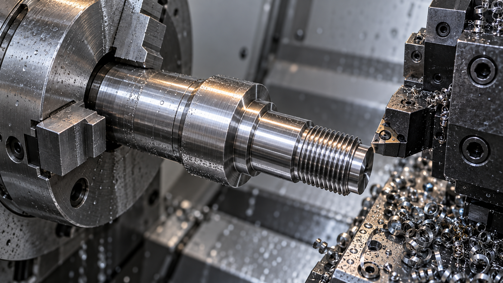
What CNC turning is actually solving: one-shot forming of revolved bodies
- Look at the feature faces: outer diameters, faces, bores, conical surfaces, threads, annular grooves—these are turning's home turf. Flat faces, keyways, side counterbores, and irregular cavities belong to milling.
- Look at whether a second setup is needed: if the part is "a flat on a shaft + an eccentric hole at the shaft end," turning it and then moving to a milling machine for another clamping can drop coaxiality from 0.02 to over 0.05. That's where the value of turn-mill's reduced setups comes in.
- Look at batch size and shape: for a single piece, an odd shape, or internal flow channels—3D printing or silicone casting may be faster; only when true revolved-surface precision is needed and the quantity is a few to a few dozen does CNC turning hold up.
How to choose between turning and turn-mill: first see which face the feature lies on
It's not uncommon for the same revolved-body drawing to be quoted at double the price. The reason is often not the material or tolerance, but "which face these features lie on." To judge turning, milling, or turn-mill, you don't need to memorize machine models first—first classify the features on the drawing by position.
Revolved surfaces, faces, external threads, bores—these features around the spindle axis are CNC turning's natural territory. The workpiece rotates and the tool feeds in a straight line; one pass completes a section of revolved surface with no tool marks from overlapping passes, and roundness is easy to keep stable. As long as the main body of the part is a revolved body, turning is usually the first and lowest-cost operation.
The trouble lies in another class of features: side flats, eccentric holes on a flange, cross holes perpendicular to the axis, and keyways on the outside. They aren't on revolved surfaces, and a lathe with a single-point tool can't produce them. The traditional approach is to flip the part for a second setup on a milling machine, or make an eccentric fixture so the lathe can "barely" machine it. A second setup means re-alignment, and both coaxiality and position tolerance gain another layer of error transfer. A common industry practice is: as long as there are more than two or three side features, or there are position-tolerance requirements relative to the spindle, go straight to milling or turn-mill rather than forcing it on a lathe.
A criteria table: feature position determines operation assignment
Once you map features to operations, the trade-offs become clear:
- Outer diameters, faces, conical surfaces, bores, external/internal threads—CNC turning can complete them in one setup, with no extra operation needed.
- Side flats, keyways, flange eccentric holes—assign to milling, or complete them in one setup using the C-axis/powered tool turret of a turn-mill.
- Cross holes perpendicular to the axis, small radial holes—turn-mill can eliminate the second setup; if there are few and their positions are loose, you can also turn first and drill later.
- Non-revolved contours (irregular outer profiles, thin sheets)—go directly to milling, 3D printing, or sheet metal; don't force turning.
The value of turn-mill in one sentence: compressing features that would otherwise require two or three setups into a single setup. Fewer setups mean less accumulated error, and coaxiality and position tolerance are easier to achieve. It's not about showing off the number of axes or a rotary table. If all the key features on the drawing are on revolved surfaces, using a five-axis turn-mill actually makes a simple part expensive. Conversely, if there are many side features and tight position tolerances, the alignment time and scrap rate saved by fewer setups are often worth more than the machine's hourly rate.
Common CNC turning operations: which features on the drawing the 10 types of actions correspond to
- Outer diameter turning: follow the longest outer contour line, from the face to the shoulder. Use an external turning tool; radial depth of cut and feed determine surface roughness, and tool deflection is most pronounced when the length-to-diameter ratio is large.
- Face turning: follow the plane perpendicular to the axis. The face is the datum for all subsequent length dimensions; if the face isn't flat, everything after it is off.
- Grooving: a section on the drawing that suddenly narrows in width, usually a relief groove, retaining ring groove, or O-ring groove. Grooving tools have poor rigidity, and when the groove width-to-depth ratio exceeds 3:1, chatter is likely.
- Parting off: the line at the end of the bar stock perpendicular to the axis, separating the part from the stock. The parting tool is the thinnest, so the feed must be slow.
- Thread turning: lines marked M, Tr, G, or with a thread profile angle. The threading tool must make multiple passes; pitch and thread depth determine the number of passes, and fine threads are more prone to cross-threading than coarse threads.
- Boring: the bore dimension line. The longer the boring bar overhang, the worse the rigidity; when the depth-to-diameter ratio exceeds 4:1, the bore mouth tends to be large and the bore bottom tends to be small.
- Reaming: when a bore is marked with H7 or H8 precision, a reamer is often needed after turning to finish it; this is a semi-finishing method.
- Knurling: The drawing shows a diamond or straight knurl symbol, used for grip on handles. After knurling, the outer diameter will grow, so allowance must be reserved.
- Form turning: For arcs, conical surfaces, and spherical contours, use a form tool or CNC interpolation to cut in one pass. The tool nose radius must match the contour.
- Drilling: For axial holes such as center holes and oil holes, this can be done on a lathe with a tailstock or turret drill. Eccentric holes require dedicated fixtures.
Workholding and datums: the most underestimated aspect of CNC turning
Coaxiality and face perpendicularity on the drawing are ultimately realized by the jaws and datum surfaces. In the same CNC turning process, completing the part in one setup versus flipping it for two setups can result in a coaxiality difference of an order of magnitude. To judge whether a rotational part drawing is easy to make, first ask: where is the datum, and how many setups are needed?
Applicable boundaries of common workholding methods
The three-jaw chuck is versatile and provides strong clamping force, but repeat positioning is poor, with runout often in the 0.02–0.05 mm range. It suits rough turning and general-precision outer diameters. Soft jaws are bored to the workpiece profile, improving positioning accuracy by a step, and are often used for finish turning and maintaining consistency in secondary setups. Spring collets clamp evenly with low runout and are an efficient choice for slender shafts and small-diameter parts, but the clamping range is narrow—one collet corresponds to one diameter range.
For internal bore locating, use a mandrel (arbor): first turn the datum bore, then mount it on the mandrel to turn the outer diameter, transferring the bore datum to the outer diameter. This is a conventional practice for high coaxiality requirements. Face driving (face driver dogs) suits turning the full length of a shaft in one setup, eliminating the need to flip. Workpieces with large length-to-diameter ratios must use a steady rest or follow rest: the steady rest supports the static section, while the follow rest moves with the tool to support the cutting point. This is key to controlling deflection and taper.
Flipping to turn the other end: how datum transfer accumulates errors
Typical scenario: one end of a stepped shaft is clamped and turned, then released and flipped to clamp the other end to turn the remaining outer diameter. The radial locating datums differ between the two setups, and chuck runout, clamping deformation, and face contact errors all stack onto coaxiality. If the datum surface from the first setup is itself not flat, the axis in the second setup will be off. The result often shows as out-of-tolerance coaxiality between the two ends and noticeable runout at the middle step.
The countermeasures are practical: critical rotational surfaces that can be completed in one setup should be done in one setup as much as possible. When flipping is unavoidable, in the first setup also turn a reusable locating datum (such as a finish-turned outer diameter or bore), and in the second setup locate on that datum using a mandrel or soft jaws. Leave finishing allowance on critical mating surfaces and finish-turn them uniformly after flipping. Writing the "datum" into the drawing or process card saves more trouble than fitting after the fact.
Length-to-diameter ratio: a common criterion for workholding plans
Common industry experience: with an overhang length-to-diameter ratio (overhang length / diameter) within 3 times, a standard chuck can usually hold it without much issue; at 4–6 times, the risk of deflection and taper rises noticeably, and a steady rest or follow rest is usually needed; beyond 6–8 times, most cases require a follow rest combined with small depth of cut and low feed, or a different process route. These are only order-of-magnitude references for judgment. Specifics must be confirmed against drawing tolerances, material rigidity, and the actual machine and tooling—they cannot be treated as guaranteed values.
For thin-walled parts, the opposite also applies: clamping force itself deforms the workpiece, which springs back after release. In this case, axial clamping, increased contact area, and light clamping in multiple stages are often more effective than simply increasing clamping force. Once the workholding plan is set, whether CNC turning can reproduce stably is largely determined.
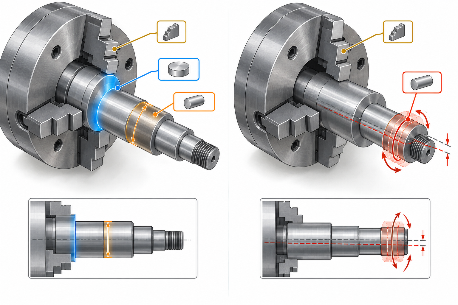
Undercuts, thread runout, and bore bottoms: not reproducible if not specified on the drawing
External undercut: width and depth determine whether the tool can "get through"
Thread runout: cannot be screwed all the way in if not specified
Bore bottom: fillet radius and overtravel space
Face chamfers and relief grooves: assembly guidance and tool clearance
Material, tolerance, and surface roughness: three constraints on CNC turning feasibility
For the same drawing, changing the material, tolerance band, or roughness requirement will cause quotes and yield to diverge noticeably. These three are not parallel parameters but mutually constraining constraints: material determines how chips break and how long the tool can cut; tolerance band determines whether finish turning or grinding is needed; and roughness is often the item written overly tight out of habit and most likely to be questioned. To judge whether CNC turning can do it and whether it is worth doing, first look at the three separately.
Material determines chip form and tool life
Free-machining steel (such as 12L14 and 1215 types) turns most smoothly, with short, easily broken chips that do not tangle around the tool, and surfaces are easy to make fine; ordinary carbon steel and alloy steel are slightly stickier and require suitable speed and feed to break the chips. Stainless steel is another category: 304/316 work-harden noticeably. With too small a depth of cut, the tool rubs on the hardened layer, the tool tip wears quickly, the surface looks bright but dimensions begin to drift. Common industry practice is to maintain sufficient feed per revolution so the tool tip cuts below the hardened layer rather than lightly rubbing.
Aluminum alloys (6061, 7075) turn quickly and easily, but tend to stick to the tool and form built-up edge, which actually worsens the surface during finish turning; this is controlled with high speed, large rake angle, and cutting fluid. Brass chips are fragmented and break easily, making it a relatively worry-free material. Titanium alloys have poor thermal conductivity, concentrating heat at the tool tip, so cutting speed must be significantly reduced, otherwise the tool burns. Engineering plastics (POM, PEEK, nylon) have low cutting forces, but deform with slightly too much clamping force, and tend to burr and produce stringy chips that tangle. These differences are directly reflected in quotes—for the same features, changing material often has a greater impact than changing machines.
Tolerance band and roughness are two sides of one thing
Dimensional tolerance and surface roughness are highly coupled in turning. For conventional outer diameter turning, common industry achievable levels are IT8–IT9; to stably achieve IT7 or tighter usually requires finish turning, reduced depth of cut, controlled tool nose radius, or simply leaving grinding allowance. Roughness is similar: ordinary turning commonly achieves around Ra3.2, and under good conditions can reach Ra1.6; going further to Ra0.8 or Ra0.4 often requires finish turning, grinding, or rolling, with different costs and process routes.
Therefore, specifying Ra1.6 on non-mating surfaces on a drawing is often just habit, not a functional requirement. Relaxing an exposed but non-contacting surface from Ra1.6 to Ra3.2 often eliminates a finish turning or polishing step with no effect on assembly. What truly should be tightened are mating surfaces, sealing surfaces, and sliding surfaces. The way to judge is simple: ask "what does this surface contact, and what ensures the fit?" If there is no answer, the roughness can most likely be relaxed.

Length-to-diameter ratio, thin walls, and interrupted cutting: the three typical failure entry points of CNC turning
Excessive length-to-diameter ratio: tool deflection, taper, and dimensional drift
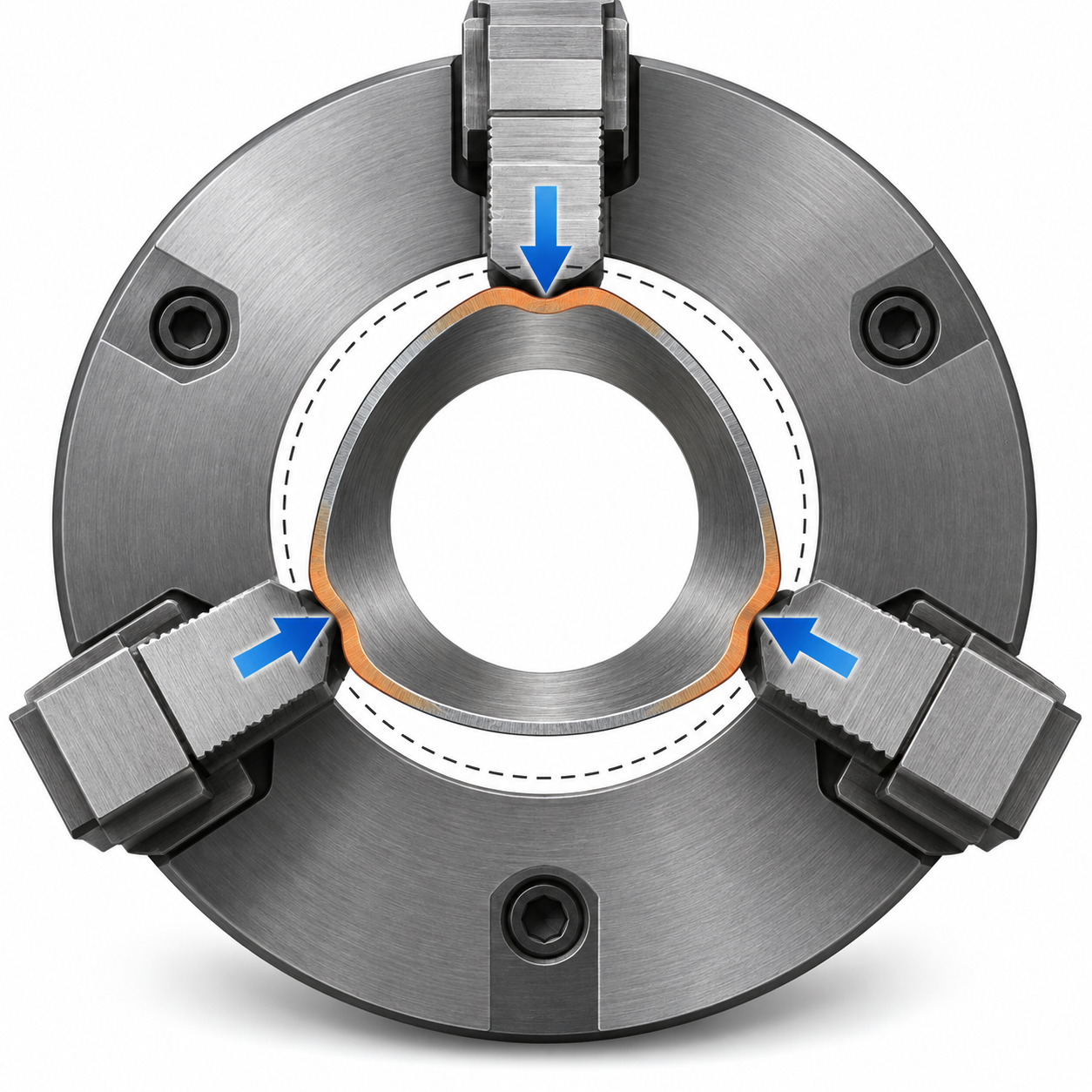
Thin-walled parts: where clamping deformation and chatter marks come from
Interrupted cutting: tool tip life and dimensional consistency under impact load
Before quoting CNC turning, what should be confirmed first on the drawing
Frequently asked questions
The questions below all come from the specific judgment points in the previous text: fixturing datum, relief groove callouts, the trade-off between tolerance and roughness, and the failure entry points of length-to-diameter ratio and thin walls. The answers give criteria you can check against, not guaranteed values.
For the same rotational part drawing, why do quotes differ so much when the fixturing method changes?
Because the number of setups directly determines labor time and inspection fixtures. One setup can turn the outer diameter, face, and bore at the same time, and coaxiality is guaranteed by the machine itself; turning the other end after flipping requires re-alignment, and coaxiality becomes the superposition of two datums, often requiring an additional dial indicator or soft jaw turning operation. The quote difference mainly comes from the number of setups, whether a mandrel or steady rest is needed, and the accompanying increase in inspection actions, not simply the material cost.
If relief grooves and thread runout are not called out, can the machinist decide them himself?
He can, but what he decides are his habitual values, which may not match your mating part. The relief groove width, depth, and thread runout length determine whether the thread can be tightened all the way and whether it will bottom out during assembly. It is recommended to call out the groove width, groove bottom fillet, and runout form on the drawing (for example, runout per GB/T 3), and to review them together with the interference relationship of the mating part. Not calling them out is equivalent to leaving reproducibility to luck.
If the surface roughness of non-mating surfaces is relaxed from Ra1.6 to Ra3.2, can it really save cost?
Usually yes. Finer roughness often means smaller feed and lighter depth of cut, and sometimes requires a tool change or an additional finishing or grinding operation, which increases labor time and tool consumption. The premise is that the surface truly does not participate in fitting, sealing, or sliding. The way to judge is to see whether it has a fit tolerance, whether it contacts a seal ring or O-ring, and whether there is an appearance requirement. A common industry practice is Ra0.8–1.6 for mating surfaces and Ra3.2–6.3 for non-mating surfaces, subject to confirmation against the drawing and actual machining.
At what length-to-diameter ratio should a follower rest or steady rest be considered?
There is no one-size-fits-all number. Common industry experience is that after the length-to-diameter ratio exceeds 4–5 times, tool deflection and taper begin to become obvious, and above 8–10 times a follower rest, steady rest, or tailstock center is usually needed for support. The real criterion is the part rigidity, the material cutting force, and the tolerance zone you require: at the same length-to-diameter ratio, an aluminum alloy slender shaft and a stainless steel slender shaft behave completely differently. It is recommended to call out the tolerances and datums of the critical sections on the drawing and let the process side decide the support plan.
If a thin-walled cylindrical part drifts dimensionally after turning, is it a machine problem or a process problem?
In most cases it is the combined effect of clamping deformation and cutting heat. Radial clamping by a three-jaw chuck makes a thin-walled part become round in the clamped state and spring back after release, so the result differs depending on when you measure. Common countermeasures are to switch to soft jaws, increase the contact area, reduce clamping force, or change to axial clamping; at the same time control cutting heat and separate roughing and finishing. If the drawing allows, you can also leave stock, release the clamp, and then finish turn. This type of problem needs to be confirmed together with the process side regarding the measurement state and datum.
Key takeaways
- The process ceiling of CNC turning is usually determined by workholding: the more faces a single setup can cover, the more stable the coaxiality and face perpendicularity; a second setup is the entry point for error and cost.
- "Non-functional details" like relief grooves, thread runout, and fillets at the bottom of bores determine whether the tool can get through. If the drawing doesn't specify them, the machinist has to decide on the spot, and the result isn't reproducible.
- Length-to-diameter ratio, thin walls, and interrupted cutting are the three typical failure entry points in turning; common industry rules of thumb can only serve as criteria—specific dimensions must be confirmed against the drawing and the actual machine.
- Surface roughness and tolerances aren't better the higher they are: relaxing a non-mating surface from Ra1.6 to Ra3.2 often saves more cost than changing the material.
- Drawing review order before quoting: datums and workholding → key tolerance bands → relief grooves and threads → material and heat treatment → surface treatment and inspection.



