What Makes Complex Part Machining Hard: Count Setups First, Then Talk Precision
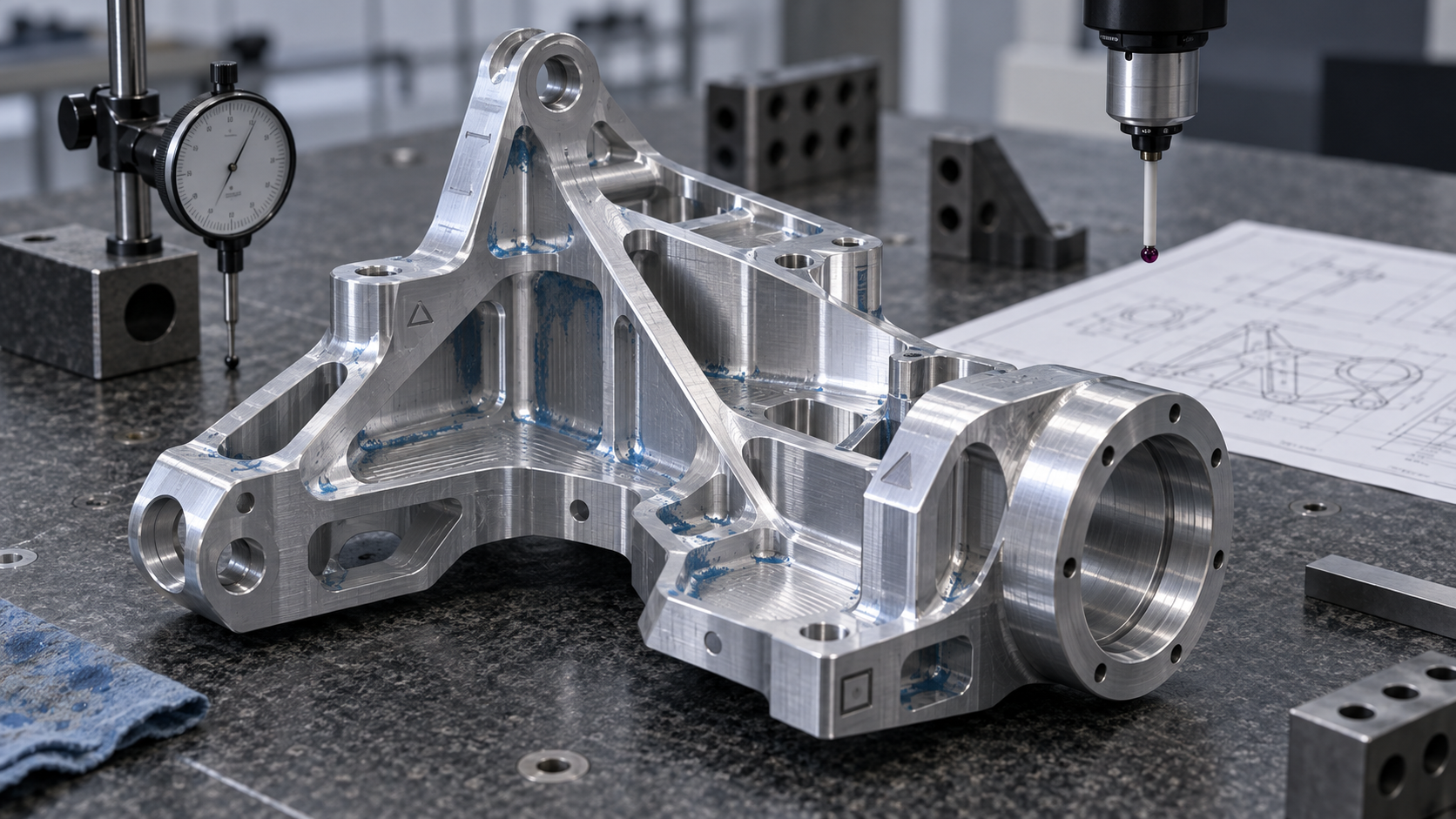
Take an aluminum bracket with a 30° angled face, a 60 mm deep internal cavity, and a 1.5 mm side wall and ask: can it be made? Most shops will say yes. The real questions are how many times it must be flipped, how many tools changed, where the datums are, and what will be used to measure it in the end. The barrier in complex part machining is rarely the repeat positioning accuracy of a single machine; it's how errors accumulate once these four things are chained together.
Complexity comes from roughly three sources. The first is geometric accessibility: whether the tool can reach in, at what attitude it enters, and where the interference zones are. Deep cavities depend on tool length-to-diameter ratio, angled faces depend on spindle tilt angle, and internal corner cleanup depends on minimum tool radius. The second is rigidity and deformation: thin walls, slender overhangs, and thin base plates deflect, yield, and distort under cutting forces. The third is measurability: the drawing specifies position tolerance, but if there is no datum surface on the part where a dial indicator or probe can be set up, the measurement conclusion won't hold.
Apply these three to the bracket just mentioned. Machining it on a 3-axis machine requires milling the cavity on the front, flipping to mill the back, then flipping twice more to make holes on the two angled faces. Each flip requires re-alignment, and alignment errors, fixture locating surface errors, and chip residue errors all stack into the final dimensions. A common industry rule of thumb is: each additional setup often increases cumulative positional error by an order of magnitude—the specific value varies with fixturing and alignment method and must be confirmed against the drawing tolerance band and actual process. A 5-axis machine can absorb this accumulation in a single setup, but only if tool accessibility and rigidity are both adequate.
So this article doesn't list equipment; it follows a decision chain: geometry features → fixturing datums → equipment selection → tolerance allocation → inspection loop. Each link provides usable criteria and boundaries, rather than adjectives like "high precision, high efficiency."
Fixturing, Datums, and Process Routing: The Most Underestimated Part of Complex Part Machining
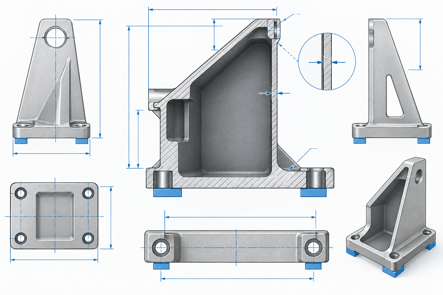
Datum Unification: Design Datums, Process Datums, and Inspection Datums Should Coincide as Much as Possible
The One-Setup Principle and the Boundaries of Common Fixturing Methods
- Soft jaws / turning chucks: suitable for rotational parts, can conform to machined surfaces to reduce clamping marks, but do not solve the locating problem for irregular parts.
- Dedicated fixtures: locating and clamping can be designed for the part, suitable for complex parts with some batch volume; for one-off or small batches, fixture cost may exceed machining cost and must be weighed.
- Vacuum chucks: suitable for thin plates and large flat parts, with uniform clamping force and low risk of crushing deformation, but poor sealing on curved surfaces and parts with through-holes.
- Zero-point positioning systems: solidify the fixturing datum onto a pallet for rapid switching between operations; the premise is that the pallet itself has stable precision and the part can be reliably fixed to the pallet.
Selecting Processes by Geometry Features: Matching Deep Cavities, Thin Walls, Angled Faces, and Irregular Holes
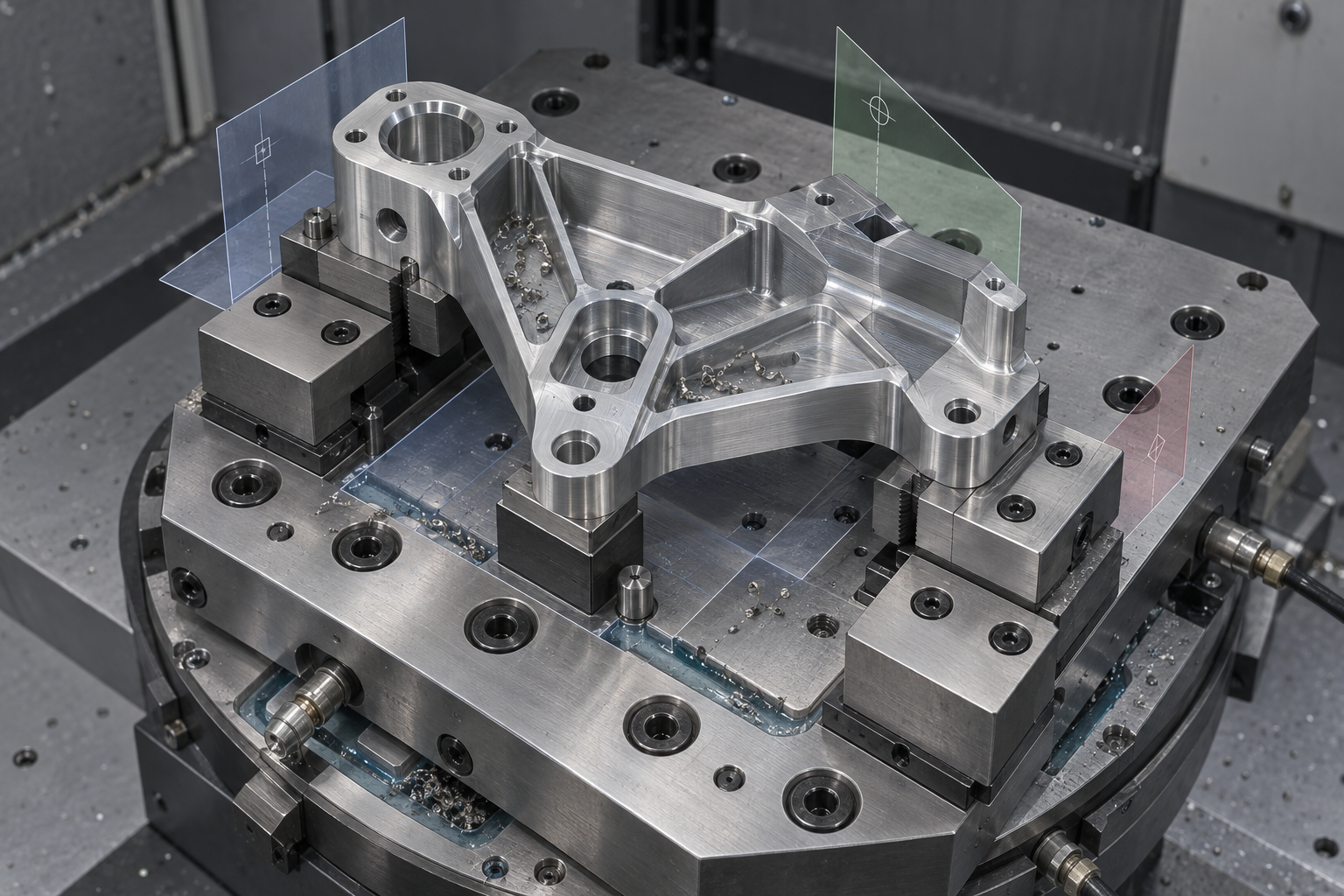
For the same complex part drawing, different machinists often quote routings that differ by two or three setups. The difference is usually not in equipment age, but in whether geometry features have been matched to machining capabilities. Below, several common feature types are broken down; the criteria are conservative, and specific values should be confirmed against the drawing and supplier.
Deep Cavities and Narrow Slots: Check Tool Length-to-Diameter Ratio First, Then Whether It Can Be Milled
The difficulty with deep cavities is tool overhang. Once the length-to-diameter ratio (overhang length ÷ shank diameter) exceeds the common industry range of 4–5×, deflection and chatter become the main error sources, producing regular marks on the surface and dimensions biased to one side. The countermeasure is not to force it, but to use layered cutting, switch to a large-diameter short tool for roughing first, and use plunge milling or EDM for corner cleanup at the cavity bottom. If the cavity depth exceeds the tool's reachable depth, the standard approach is segmented machining or switching to EDM—don't expect one long tool to go all the way.
Thin Walls and Irregular Holes: Cutting Forces and Clamping Deformation Are the Main Causes
Errors in thin-walled parts (where the wall thickness-to-height ratio is small) rarely come from machine geometric accuracy; they come more from cutting forces and clamping forces pushing the workpiece out of shape, which springs back after release. Common industry practices include leaving ribs, symmetric material removal, reducing radial depth of cut, and using soft jaws or vacuum chucks to distribute clamping. Irregular holes, angled holes, and cross holes test the tool entry and exit path—if they can be machined in one setup with 5-axis spindle tilting, avoid multiple flips and re-alignment. If the batch is small, the shape is complex, and surface requirements are not high, vacuum casting can serve as a transitional option, but dimensional stability and material properties differ from direct machining and must be confirmed in advance.
Inclined and compound surfaces: replacing multiple refixturing with a single five-axis setup
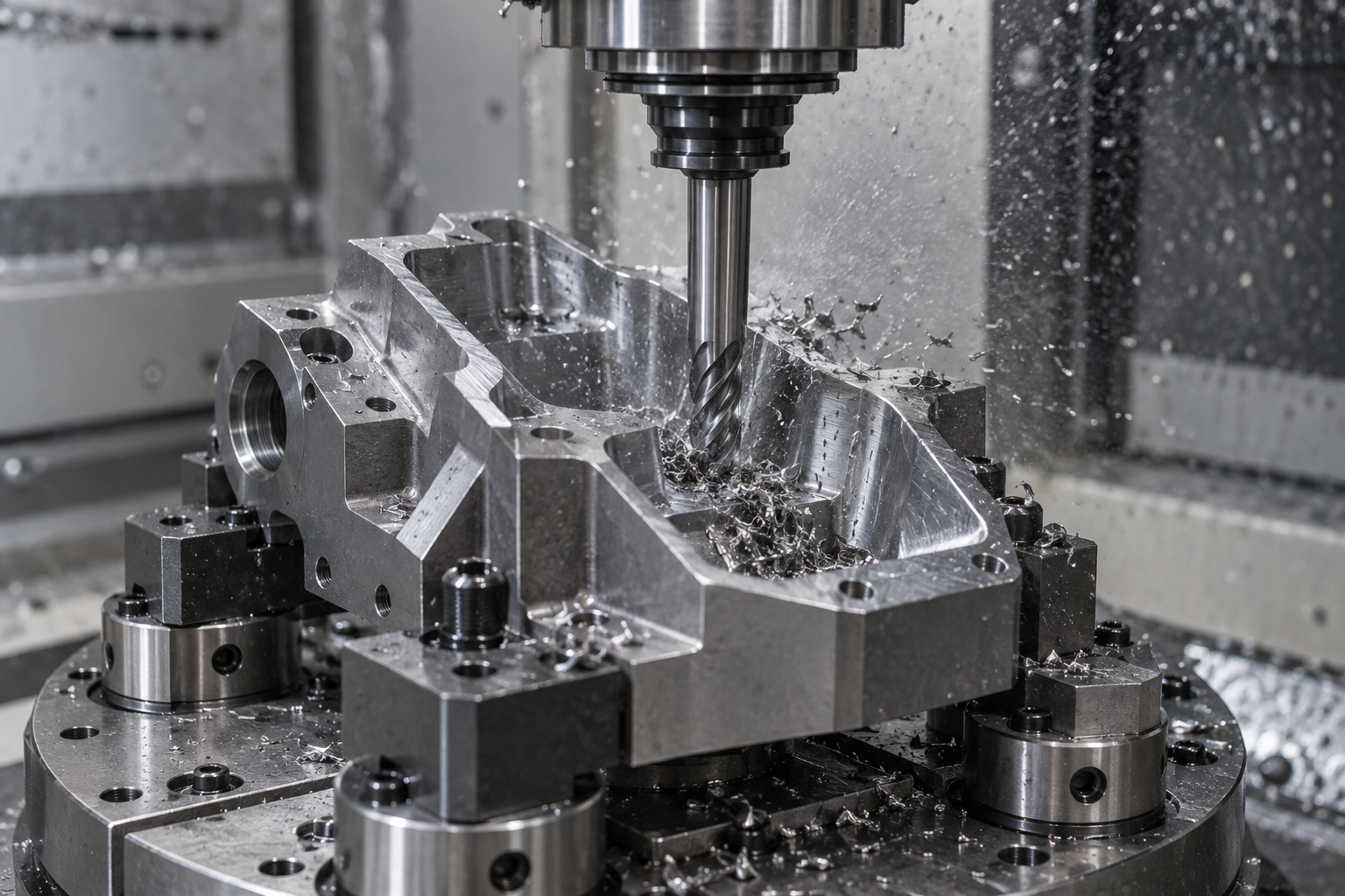
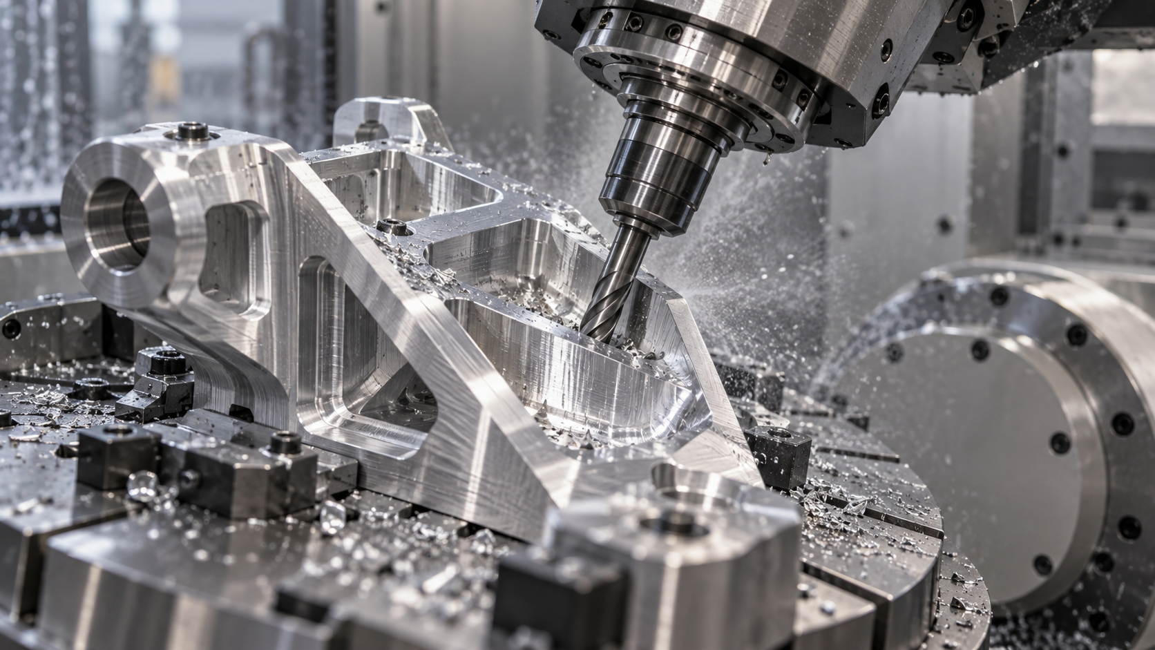
For parts with inclined surfaces, compound angles, and spatial curved surfaces, three-axis machining relies on multiple setups and dedicated fixtures to piece them together. Each refixturing introduces re-alignment errors, which can accumulate and consume most of the tolerance. This is where the value of five-axis comes in: completing multi-face machining in a single setup, compressing the number of setups from three or four down to one, and significantly reducing sources of error. But five-axis is not a cure-all—for parts that are mainly flat, with shallow pockets and simple features, using five-axis is actually wasteful: programming and tooling costs go up, but the benefits don't materialize. The test question is simple: if this part were taken off the five-axis, how many times would it need to be flipped? The more flips, the more five-axis is worth considering.
From three-axis to five-axis, turn-mill and EDM: equipment selection criteria for complex part machining
Three-axis with multiple setups vs. five-axis in a single setup: where the cost difference lies
Turn-mill: saving setups on rotationally asymmetric parts, at the cost of programming and tooling
EDM and wire cutting: irreplaceability for hard materials, sharp corners, and narrow slots
When five-axis is wasteful: shallow pockets, mainly flat, small batch and simple features
Cost-driving tolerances and surface roughness: the most expensive numbers in complex part machining
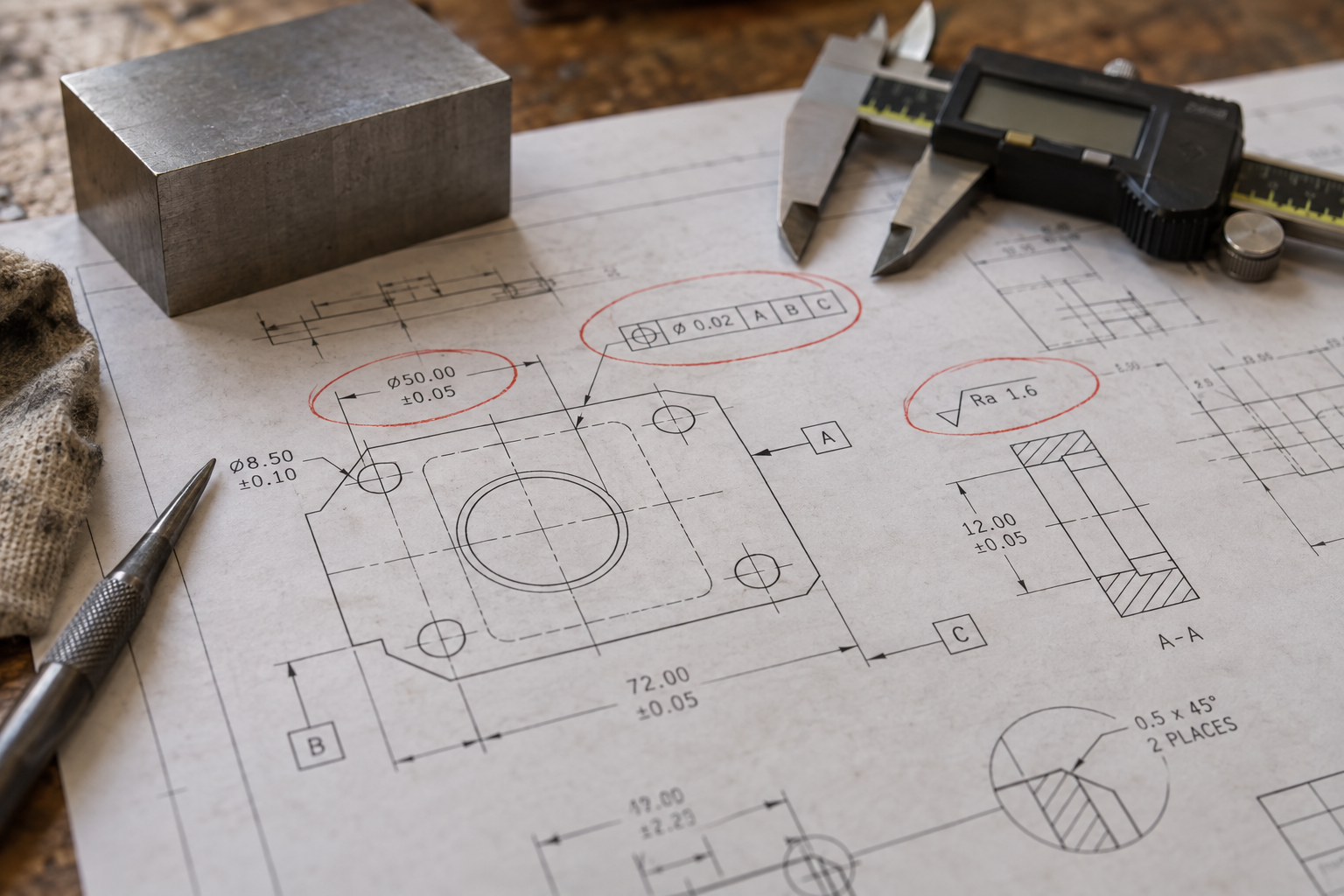
The cost of complex part machining is often not driven apart by geometric shape, but by those few tolerance numbers on the drawing. For the same aluminum bracket, marking all dimensions uniformly as ±0.05 mm versus tightening mating holes to ±0.02 mm and relaxing non-functional outer shapes to ±0.2 mm can produce a noticeable difference in quote—the difference is in machining methods, labor, and scrap rate, not material. What truly determines cost on a drawing is cost-driving tolerance: which faces must be tight, which can be loose, and which machining method's achievable range these numbers fall into.
How much do labor and scrap rate rise when tolerance is tightened one grade
The relationship between dimensional tolerance and machining cost is not linear. Common industry experience is: from ±0.1 mm tightened to ±0.05 mm, most milled faces can still be covered by conventional finish milling; tightened further to ±0.02 mm or even tighter, it often requires slower feed, smaller depth of cut, multiple finishing passes, or even a more stable clamping method. Labor may rise severalfold, and the probability of out-of-tolerance rework and scrap also increases noticeably. Exactly which grade is the point where it "starts getting expensive" depends on material, feature rigidity, and machine condition, and must be confirmed according to the specific process and drawing, and cannot be generalized.
So the reasonable approach is not "mark everything tight to look professional," but to allocate by function: tighten mating faces, sealing faces, bearing seats, and guide faces; relax non-functional outer shapes, clearance zones, and decorative faces. When reviewing a drawing, it is worth first circling these functional faces, then asking—if tightened one grade, is it really needed for assembly.
Surface roughness is not better the smoother it is; it is tied to subsequent processes
Surface roughness must likewise be specified by use. Sealing faces and sliding faces usually require lower Ra, possibly needing fine milling, grinding, or lapping; while many mating faces only need to reach conventional finishing level. What is more often overlooked is: roughness callouts must align with subsequent surface treatment. Anodizing, painting, and electroplating change the surface state; if the surface is ground very smooth to final requirements before treatment, it wastes labor and may not be maintained after treatment; conversely, if a certain roughness must still be achieved after painting, the coating thickness and process must also be considered together. Roughness, like dimensional tolerance, is a functional requirement, not an aesthetic one.
Geometric tolerances: easier to miss than dimensional tolerances, and more impactful on assembly
In complex part machining, what really blocks assembly is often not dimensions, but geometric tolerances. Callouts such as parallelism, perpendicularity, position, and runout, if handled only by default unspecified tolerances, may have every individual dimension pass, yet fail to fit or fit offset when assembled. The reason is direct: dimensional tolerance governs a single dimension, while geometric tolerance governs the relationships between faces and between holes, and assembly depends precisely on these relationships.
It is recommended to clearly define the datum system on the drawing, mark critical position and runout by function, and specify the inspection method. Overly tight geometric tolerances directly drive up setup and inspection costs, but failing to mark where tightness is needed often exposes the cost only on the assembly line or at the customer site. Which direction is more expensive depends on part use and batch size, and must be judged in light of specific working conditions.
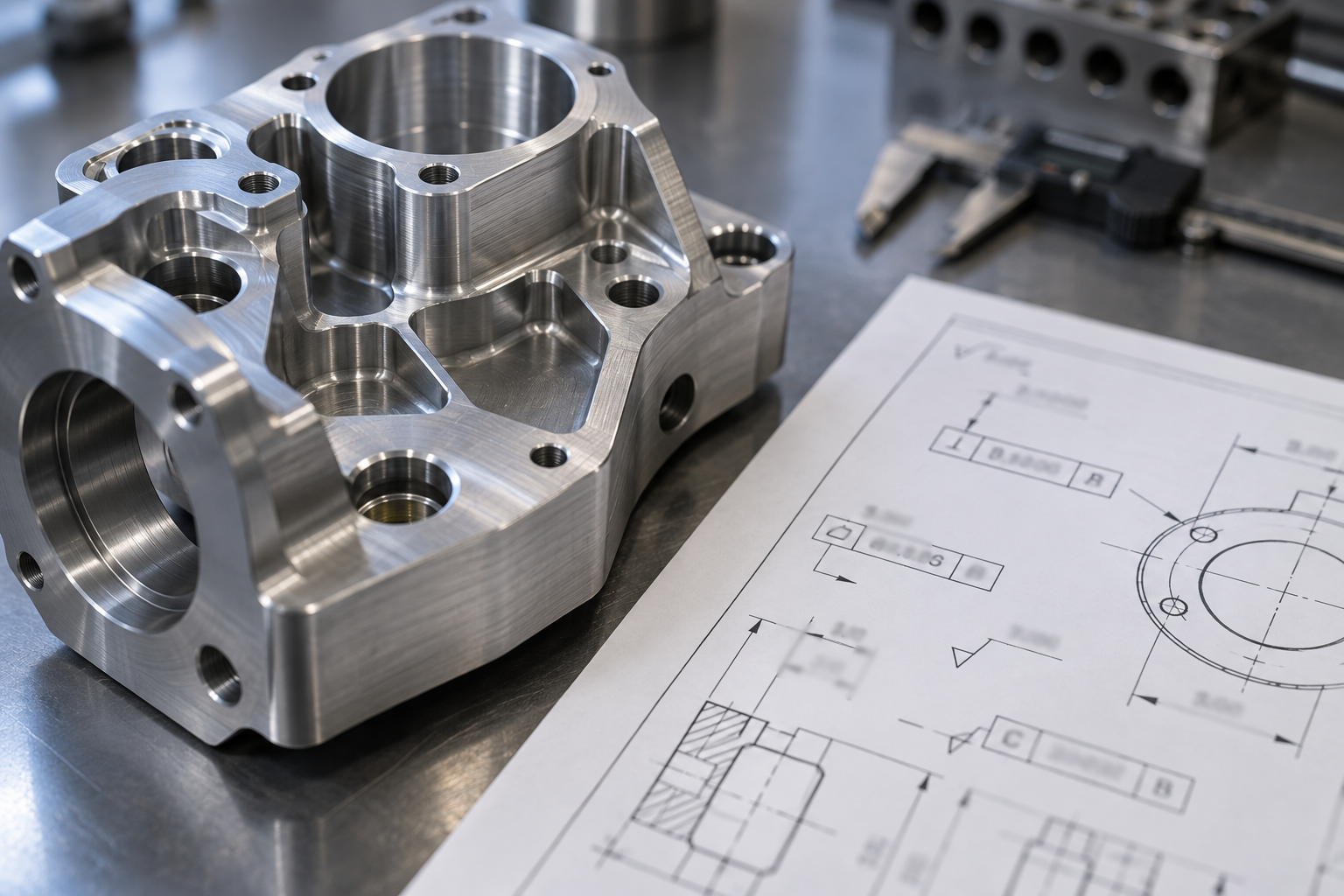
Allocating these numbers clearly is essentially a trade-off between cost and function: tight tolerances are spent where truly needed, and roughness and geometric tolerances are also set by function and impact on assembly. Every number on the drawing will ultimately appear on the quote—before marking it, think clearly about which assembly step it blocks.
Deformation, chatter, and tool life: failure modes and countermeasures in complex part machining
Thin-wall deformation: identification signals and layered material removal strategy
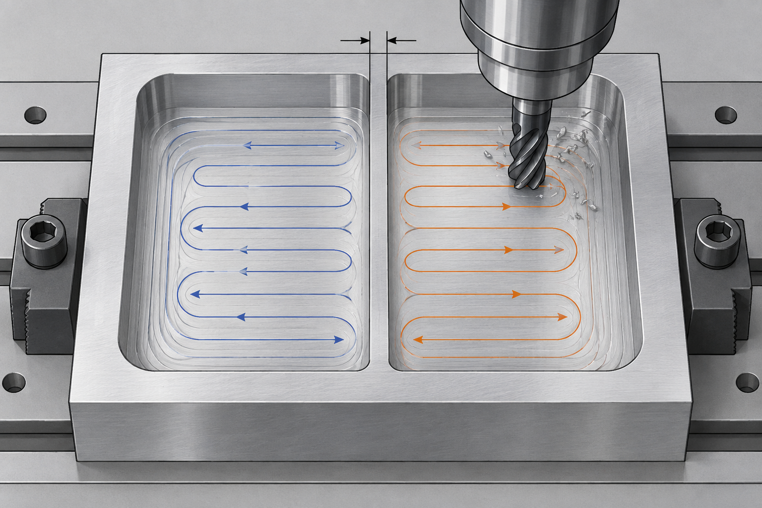
Deep-cavity tool deflection and slender tool chatter: reverse-engineering the cause from sound and marks
Residual stress and heat-treatment drift: root causes and countermeasures for post-machining warping
Inspection and closed loop: how to prove a complex machined part is qualified
Qualification in complex part machining is not "it was made," but "it can be measured accurately and judged reliably." Putting inspection at the end of the process chain is the most costly approach; the correct approach is to treat it as part of a closed loop: process datums and inspection datums are consistent, measurement points are designed to reflect assembly function, and measurement results feed back into fixturing and tool compensation. CMM, blue-light scanning, optical imaging, and dedicated gauges each have their applicable scenarios; choosing the wrong inspection method means the conclusion itself will drift.
Common inspection methods: applicable scenarios for CMM, blue-light scanning, optical imaging, and dedicated gauges
Coordinate measuring machines (CMM) are the most stable for measuring dimensions and geometric tolerances, suitable for mating surfaces, hole positions, and datum surfaces where a judgment value must be given; the drawback is limited measurement points, and contact force on thin-wall parts may cause measurement deformation. Blue-light scanning is suitable for freeform surfaces, irregular parts, and full-size deviation color maps, quickly showing overall deformation trends, but single-point absolute accuracy is usually lower than CMM and requires calibration with a standard sphere. Optical image measurement is efficient for small, flat parts with clear edges, but is prone to inaccuracy on deep cavities, reflective surfaces, and inclined surfaces. Dedicated gauges (plug gauges, test bars, functional gauges, locating fixtures) target a specific assembly feature, are the fastest and closest to the usage state, but are not universal gauges.
Judgment principle: features that determine whether assembly can fit are verified with dedicated or functional gauges; dimensions and geometric tolerances that require specific values use CMM; overall surface deformation and curved-surface deviation use blue-light scanning as a supplement. A common industry practice is to fully verify the first article with CMM or scanning, and sample key items with gauges in batch production—specific items are confirmed according to the drawing and batch size.
Datum and measurement point design: why it measures as qualified but won't assemble
"It measures as qualified but won't assemble" is usually not a machining problem, but a datum inconsistency. Design datums, process datums, and inspection datums should be unified as much as possible; if the datum is changed during inspection, the measured position tolerance or coaxiality may be completely different. Measurement points also need functional awareness: hole positions should be laid out according to the actual mating direction of the assembly pin, sealing surfaces according to the leakage path, rather than randomly picking convenient locations. The number, location, and measurement force of measurement points should be written into the inspection plan to avoid different inspectors reaching different conclusions.
First article, sampling, and in-process measurement: inspection cost should be included in the process route
The first article must be fully measured, including datums, key dimensions, geometric tolerances, and functional gauges; only after the first article passes can batch production be discussed. Sampling frequency depends on process capability: fast tool wear, large material batch variation, and thin walls prone to deformation require denser sampling. In-process measurement (machine tool probes, on-machine scanning) can reduce re-clamping, but probe accuracy, stylus length, and coolant residue all introduce errors, making it suitable for trend monitoring rather than final judgment. Inspection cost is not a quality inspection fee added afterward, but should be included in the process route—how many setups, how many measurements, and whether dedicated gauges are needed should all be clarified at the quotation stage.
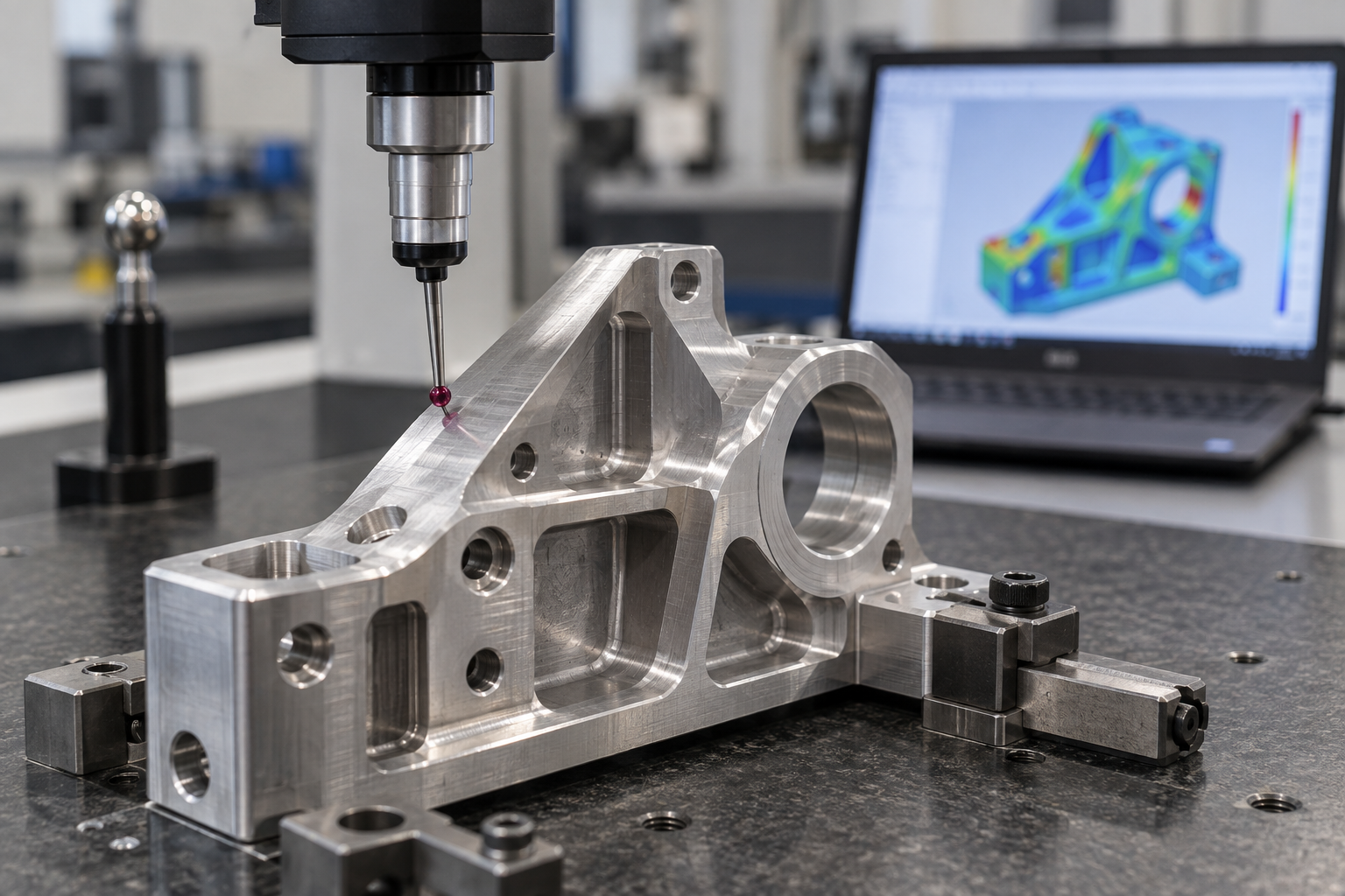
Measurement itself also has uncertainty: equipment accuracy, ambient temperature, fixturing method, and stylus shape all affect the result. The inspection method specified on the drawing should match the actual inspection—if the drawing specifies "position tolerance" but a caliper is used to measure hole spacing for judgment, the conclusion is not comparable. To form a closed loop in complex part machining, the inspection plan, drawing callouts, and process datums must be aligned in the same language; when supplementary scanning or reverse comparison is needed, refer to 3D scanning capabilities.
From drawing to quote: communication checklist and common pitfalls in complex part machining
By the time complex part machining reaches the quotation stage, the most expensive thing is never machine time, but the back-and-forth clarification emails. If the drawing is vague, the supplier can only quote based on the most conservative process, and the price naturally won't come down; conversely, if you explain the decision basis clearly in one go, the other party may be able to provide a plan close to the actual process. The checklist below covers the elements worth confirming item by item before quotation.
Seven elements to clarify before quotation
- Material and condition: beyond the grade, also specify the heat treatment condition (e.g., T6, quenched and tempered, annealed) and blank form (bar stock, plate, forging, casting). The same grade in different conditions differs greatly in machinability and subsequent deformation.
- Key tolerances: which dimensions truly affect function, and which are only reference. Marking or listing key dimensions separately is more useful than scattering tolerance zones all over the drawing.
- Datums: where the design datum is, and which surface is used for locating during assembly. If the datum is unclear, the supplier can only make assumptions, and inspection conclusions cannot be aligned.
- Surface treatment and roughness: anodizing, plating, painting, passivation, and the corresponding Ra requirements. Treatment changes dimensions, especially the effect of plating thickness on fits.
- Quantity and batch: single piece, small batch, or continuous order, which determines whether the process route follows a rapid prototyping approach or a mass production approach.
- Inspection requirements: full dimensional report, first article report, or key dimension sampling. The inspection method (CMM, scanning, dedicated gauges) should also be specified.
- Assembly relationship: what this part mates with, and what the fit clearance is. Looking at a single part drawing alone often fails to reveal the true source of tolerances.
Four recurring pitfalls
Providing only a 3D model without 2D callouts.The model can express shape, but not tolerances, datums, and surface requirements. Without these, the supplier can only quote based on general tolerances, and the result is usually not what you want.
Marking all tolerances at the same grade.Tightening everything to the same level means non-functional surfaces also follow a precision machining route. A common industry practice is to tighten mating surfaces and sealing surfaces while relaxing the rest; how much to relax depends on assembly requirements and process capability, and must be confirmed according to the drawing.
Ignoring the stress-relief operation.In complex part machining, if residual stress after roughing is not removed, warping may occur after finishing or during use. Just because it is not written on the drawing does not mean it is not needed in the process; this often must be confirmed with the supplier in advance.
Directly scaling up the sample process to batch production.The sample stage often uses rapid prototyping or single-piece machining thinking; at several hundred pieces or more, the fixturing method, tool life, and inspection rhythm must all be recalculated. Continuing the sample route will cause problems in both cost and consistency.
If you happen to have a complex part drawing on hand, you can first organize the above elements into a one-page description, then proceed with the quotation process. AGX offers AI conversational quoting; after uploading the drawing, you can confirm material, tolerances, and process route item by item, which is faster than repeated emails.
FAQ: decision follow-up questions in complex part machining
The questions below basically all come from the judgment points that recur in the previous sections: number of setups, correspondence between geometric features and equipment, tolerance allocation, deformation control, and inspection closed loop. The answers only give direction and boundaries; specific values still need to be confirmed against the drawing and process.
Why do complex part machining jobs count setups first, instead of looking at machine tool accuracy first?
Because multiple setups stack up re-alignment errors, and the machine tool's own positioning accuracy is often not the main error source. If a part is flipped four times, the deviation introduced by each alignment can be an order of magnitude larger than the single-machining error. A common industry practice is: merge as many features as possible into one setup, and unify the datum to the same set of process datums. How many setups are actually allowed depends on which face the critical tolerances fall on, and must be confirmed against the drawing.
For features like deep cavities and thin walls, is five-axis a must?
Not necessarily. Deep cavities mainly depend on the tool's length-to-diameter ratio; when the ratio is too large, tool deflection and chatter are the bottleneck, and switching to a shorter tool, segmenting the machining, or adjusting the toolpath is often more direct than changing equipment. Thin walls depend on cutting force and clamping deformation; vacuum chucks, soft jaws, and symmetric material removal are more critical. The value of five-axis lies in reducing the number of setups and improving tool accessibility—if the features themselves are simple and setups are few, five-axis may not be cost-effective. The basis for judgment is geometric accessibility and number of setups, not equipment tier.
Is it safer to specify tolerances as tightly as possible?
No. Tightening a tolerance by one grade usually raises machining time and scrap rate noticeably, and that increase is often nonlinear. Mating surfaces, sealing surfaces, and geometric tolerances with assembly relationships should be tight where needed; non-functional and cosmetic surfaces can be relaxed. A more common problem is specifying the same grade for all dimensions, which leaves the machinist unable to tell what must be held and what can be relaxed. Geometric tolerances (parallelism, position, runout) are more easily overlooked than dimensional tolerances, yet they affect assembly more directly; it is advisable to specify them separately and state the datum.
Can inspection catch warping or dimensional drift after machining?
No. Warping, residual stress release, and dimensional drift after heat treatment are all process control issues; final inspection can only detect them, not fix them. Common countermeasures include: separating rough and finish machining, scheduling stress relief or aging in between, symmetric material removal, and adjusting clamping points and cutting parameters. The identifying signals are usually changes in sound, abnormal surface patterns, and dimensions trending in one direction. If it is only discovered at finished-product inspection, the rework cost is already very high.
When should the inspection plan be decided?
At the process routing stage, not after machining when you start thinking about how to measure. CMMs, blue-light scanning, optical imaging, and dedicated gauges each have their applicable scenarios, and probe point design and datum selection directly affect the conclusion. Measurement itself also has uncertainty; if the drawing callouts and the inspection method are inconsistent, pass/fail can become a dispute. It is advisable to clarify the inspection method and datum for critical dimensions before quoting, to avoid after-the-fact measurement or repeated re-inspection.
Key takeaways
- The biggest cost driver in complex part machining is often the number of setups and datum transfers, not the cutting itself; count setups first, then talk about equipment.
- For features like deep cavities, thin walls, and slender geometries, prioritize solving tool length-to-diameter ratio and rigidity—forcing it onto a 5-axis machine won't save you from tool deflection and chatter.
- Tolerances are not better the tighter they are: only assembly, sealing, and mating surfaces are worth tightening; everything else should be relaxed to a cost-driven tolerance band that the process can reliably hold.
- The inspection plan must be decided at the quotation stage: datums, measurement points, and gauges determine whether the part can be proven conforming.
- 5-axis, turn-mill, EDM, and vacuum casting each have their failure boundaries; matching them to geometry features is more cost-effective overall than ranking by unit price.



