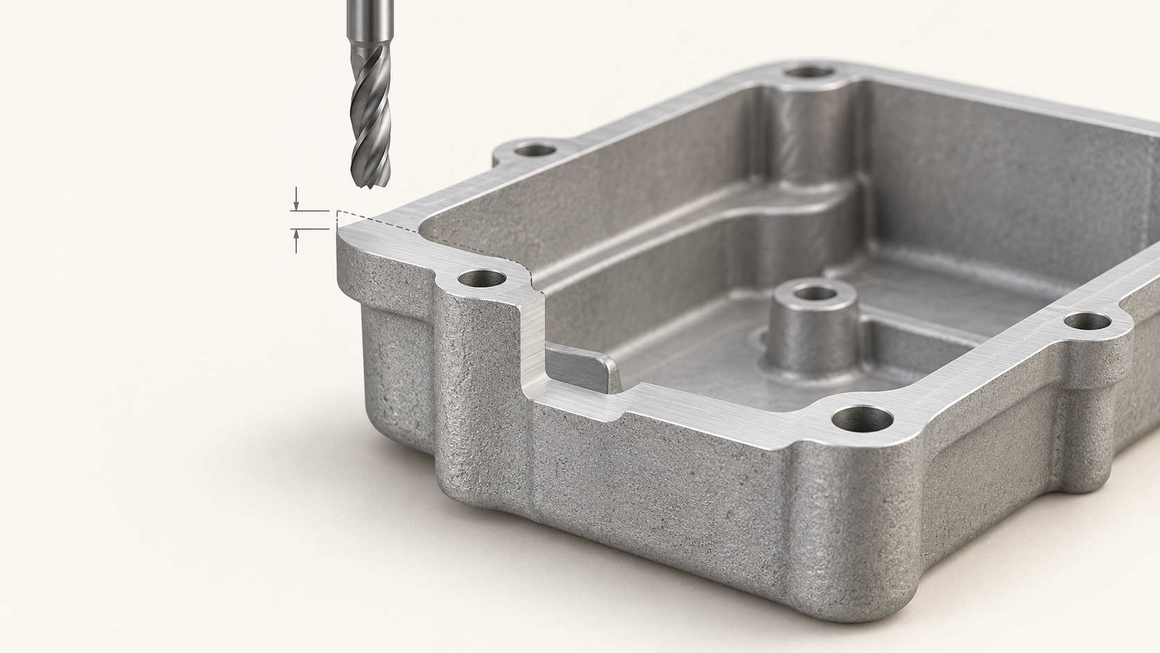
Why Can the Machining Allowance for Die-Cast Aluminum Alloys Cause Sealing-Surface and Hole-Position Failures?
A common unexpected result on the shop floor is that, to ensure the dimensions of a sealing surface, a project specifies a very large machining allowance for the die-cast aluminum alloy, yet porosity, locally insufficient wall thickness, or even deformation of the sealing surface appears after CNC machining. Another issue is that the mounting holes themselves meet their machining requirements, but their positions are offset relative to the housing datum, so they still cannot be aligned during assembly. In such cases, the problem is often not the cutting parameters, but the fact that the die-cast blank, locating datums, and allowance window were not defined together.
A larger machining allowance does not necessarily provide greater assurance. Its lower limit must cover the as-cast surface layer, dimensional variation, warpage, flash, and clamping and locating errors to ensure that the functional surface can be machined cleanly and continuously. Its upper limit is constrained by the minimum effective wall thickness after machining, the bottom thickness beneath holes, the sealing structure, and the risk of internal defects. The density of the die-cast part may differ between the surface layer and the interior; removing too much material may expose pores, shrinkage porosity, or low-density regions.
Therefore, die casting, clamping, and CNC machining should each address different types of error: die casting should produce a stable blank, while the mold and part structure should provide repeatable rough datums; CNC machining should then use precision datums to control the relationships among sealing surfaces, hole patterns, and planes. A single setup can reduce repeated locating errors, but it cannot correct blank warpage or unstable datums.
- Before mold opening, confirm which surfaces must be machined and the functional relationships among the sealing surfaces, mounting surfaces, and hole patterns.
- Define the rough datums, CNC precision datums, and datum-conversion sequence. Where necessary, reserve locating bosses or reliable datum surfaces on the mold.
- Include the minimum wall thickness after machining, bottom thickness beneath holes, flatness, hole position, and airtightness in first-article acceptance, rather than merely specifying “machining allowance.”
Calculation Limits for the Machining Allowance of Die-Cast Aluminum Alloys: One-Side Allowance, Total Allowance, and Minimum Wall Thickness
The terminology for the machining allowance of die-cast aluminum alloys must first be standardized. One-side allowance is the material thickness reserved on a given machined surface from the die-cast blank to the CNC-finished surface. When two opposing surfaces are machined simultaneously, their combined value is the total allowance. The depth of cut for an individual tool pass is a machining parameter, not the total allowance specified on the drawing; the minimum wall thickness after machining is the effective material retained in the part and must not be confused with the allowance.
Initial Calculation Framework for the Machining Allowance of Die-Cast Aluminum Alloys
In engineering, a variable-based model can first be used to establish the machining window: initial unilateral allowance ≈ allowance for covering blank-size variation + allowance for deformation or warpage compensation + allowance for covering fixturing and locating errors + thickness of the as-cast surface layer that must be removed. Dimensional variation should be based on measurements of the initial batch of blanks, rather than simply referencing the nominal die-casting dimensions. Deformation should also be assessed in conjunction with the parting line, slides, gates, and wall-thickness distribution. If datum conversion introduces positional error, simply increasing the allowance cannot correct hole-position or concentricity problems.
Back-check the upper allowance limit using the minimum wall thickness after machining
Once the allowance has been determined, the minimum wall thickness, hole-bottom thickness, and remaining material in sealing structures after machining must be calculated in reverse. For thin walls, rib roots, blind-hole bottoms, or transitions between thick and thin sections, an excessive unilateral allowance may cause the CNC tool to cut into low-density regions, exposing gas porosity, shrinkage porosity, or other casting defects, and may also leave insufficient local wall thickness. The final validation should confirm both “whether the as-cast surface layer can be removed cleanly and consistently” and “whether sufficient effective material remains.” The blank-state datum condition, post-machining dimensions, and minimum wall thickness should also be specified on the drawing or RFQ.
The first step in determining the machining allowance for die-cast aluminum alloys: establish the rough datum and CNC precision datum
Establish the datum first, then determine the machining allowance for the die-cast aluminum alloy. If the sealing surfaces, hole patterns, and mounting surfaces do not share a common locating logic, simply increasing the allowance cannot correct hole-position deviation, loss of concentricity, or errors in dimensional relationships caused by datum conversion.
The rough datum should avoid the parting line and unstable casting features
The first operation should inspect parting-line mismatch, slide marks, gate remnants, flash, and local warpage, and determine which as-cast surfaces can provide stable support for the fixture. If a large plane is deformed, it should not be directly used with the highest point as the sole datum; otherwise, localized tool engagement or unmachined areas may occur after machining. During the mold-design stage, locating bosses, reliable datum surfaces, or bottom holes can be provided to create repeatable rough-locating conditions for subsequent CNC machining.
The CNC precision datum determines how the allowance is actually removed
After rough machining, the CNC precision datum should be established based on the functional datum, and the sequence of datum conversions should be clearly defined. If the sealing surface and associated hole pattern can be completed in the same setup, this generally helps reduce repeatable locating errors. However, a single setup still cannot eliminate blank warpage, unstable locating surfaces, tool deviation, or measurement error. The pilot hole should not be evaluated solely by its machining allowance; its positional accuracy must also be confirmed to ensure that it does not transfer errors to subsequent hole locations or threads.
- The supplier should confirm: the locations of the rough datum surfaces, precision datum surfaces, locating pins, or clamping points, and whether dedicated inspection fixtures are required.
- The first-article report should record the blank datum condition, key dimensions after datum conversion, and the positional relationships among the hole locations and sealing surfaces.
- If the datum surface itself has obvious casting deformation, the locating scheme and allowance window should first be corrected based on blank measurement results, rather than directly increasing the cutting depth of the toolpath.
Determine the machining allowance for die-cast aluminum alloys by functional surface: sealing surfaces, holes, bearing seats, and cosmetic surfaces
The machining allowance for a die-cast aluminum alloy part should not be assigned as a single value for the entire part. First group the functional surfaces, then determine which blank errors must be eliminated by CNC machining and which areas should retain as-cast material as much as possible. An allowance that is too small may leave flash, cold shuts, or uncleaned surface layers; an allowance that is too large may expose gas porosity or shrinkage porosity, or cause thin walls to deform during cutting and clamping.
| Surface or feature | Allowance evaluation focus | Risk of allowance being too small | Risk of allowance being too large | First-article inspection |
|---|---|---|---|---|
| Sealing surfaces, mounting surfaces | Covers warpage, as-cast roughness, and positioning errors, ensuring uninterrupted full cutting | Localized unmachined areas, unstable flatness or airtightness | Cutting into a porosity zone, resulting in insufficient wall thickness | Flatness, machining coverage, minimum wall thickness, and airtightness |
| Bearing bores and fit bores | Hole position, coaxiality, fixturing datum, and bore machining allowance | The as-cast surface or deformation affects assembly | Thinned bore walls may expose porosity | Bore diameter, hole position, coaxiality, and bore wall thickness |
| Threaded holes and mounting holes | Pilot hole position, hole-bottom thickness, and effective thread depth | Incomplete threads or offset hole positions | Breakthrough at the hole bottom or insufficient local wall thickness | Pilot hole, thread GO/NO-GO gauges, and hole-bottom thickness |
| Appearance surfaces, thin walls, and areas near ribs | Whether machining is mandatory, texture consistency, and local stiffness | Residual as-cast defects or inconsistent appearance | Localized tool engagement, deformation, or cutting into defects | Appearance, profile, deformation, and remaining wall thickness |
Machining allowance on sealing surfaces and bearing bores must be defined in accordance with assembly relationships
The key point for the sealing surface is to confirm whether it has been continuously and completely cut after machining, rather than checking only the dimension at a particular measurement point. For bearing bores, the bore location, coaxiality, and fit datum should be evaluated together. A single setup can reduce repeated positioning errors, but it cannot eliminate die-cast blank warpage or datum instability. Some supplier documentation lists tight bearing-bore tolerances and sealing-surface flatness as post-CNC control items. Such data can only serve as conditional references; final confirmation still requires consideration of the tooling, workholding, measurement method, and first-article results.
How should the lower limit of the machining allowance for die-cast aluminum alloys account for blank deviations, deformation, and the as-cast surface layer?
Guiding principle: The lower limit of the machining allowance for die-cast aluminum alloys is not determined by as-cast roughness alone. It must cover the actual deviation of the functional surface relative to the machining datum. Differences in dimensional shrinkage, warpage, parting-line mismatch, flash, local incomplete filling, and workholding and locating errors may all cause different machining depths at different positions on the same plane. The allowance should ensure that the target area can be continuously cut clean, but it must not be estimated solely from one highest or lowest point.
The machining allowance for die-cast aluminum alloys must account for the distribution of blank deviations
Take a large housing sealing surface as an example. If the blank has slight warpage, the tool may cut into some areas while merely wiping across others, ultimately leaving unmachined as-cast surfaces. The first batch of blanks should not be measured at only one corner point. Instead, a measurement coordinate system should be established using the proposed rough or finished datum, and multiple points on the functional surface, both ends of the plane, and thin-wall connection areas should be checked. Where necessary, coordinate measuring or scanning methods can be used to record the deviation distribution before determining the initial allowance and rough-machining toolpath.
Measurement and documentation requirements for the machining allowance of die-cast aluminum alloys
- Define the blank condition: confirm whether the gates and flash have been removed and whether the blank has been cleaned or corrected before measurement.
- Fix the measurement datum: record the datum surface, locating holes, or locating bosses to avoid mixing data obtained from different datums.
- Cover critical points: include the edges of the sealing surface, areas near the hole pattern, wall-thickness transition zones, and large planes prone to warpage.
- Specify the acceptance criteria: distinguish dimensional deviations, locally unmachined areas, surface defects, and deformation caused by workholding, and feed the measured results back into the allowance window and process plan.
Therefore, the initial machining allowance for die-cast aluminum alloys can only be proposed through theoretical estimation and cannot replace blank data. If blank deviations are primarily caused by an unstable datum or significant warpage, simply increasing the allowance may not solve the problem and may instead intrude into thin-wall or defect-sensitive areas. A more reliable approach is to first confirm the blank measurement datum, measurement points, and acceptance criteria, then use first-article machining results to verify that the material has been completely cut clean and that the designed wall thickness has been maintained.
Why can an excessive allowance expose porosity and shrinkage cavities and cause thin-wall deformation?
The surface layer of die-cast aluminum alloy does not indicate that the condition of the internal material is completely uniform. Areas near the surface are generally denser, but excessive material removal may penetrate into regions with a higher concentration of pores, shrinkage cavities, or other defects. Conversely, an allowance that is too small may leave oxide scale, cold shuts, flash, or locally unmachined areas. Therefore, a machining allowance is not safer simply because it is larger; it establishes a process window between completely removing the as-cast surface layer and retaining sufficient sound material.
Machining allowance for die-cast aluminum alloys and the risk of thin-wall deformation
For a housing sealing surface, increasing the allowance may cause the tool to cut into low-density areas, resulting in pinholes, leakage, or locally insufficient wall thickness. Thin walls, rib roots, and wall-thickness transition areas are also susceptible to the effects of cutting forces, workholding forces, and the release of residual stress, which may appear as degraded flatness or springback after machining. A single setup can reduce repeated positioning errors, but it cannot eliminate blank warpage, datum instability, or machining deformation.
| Inspection item | Risks to be confirmed | First-article inspection action |
|---|---|---|
| Sealing surface | Porosity, locally unmachined areas, and insufficient wall thickness | Check complete continuous cutting, flatness, minimum wall thickness, and airtightness |
| Mounting holes and hole patterns | Hole position offset, excessively thin hole bottom, datum transformation error | Check hole position, hole diameter, hole-bottom thickness, and assembly relationships |
| Near thin walls and ribs | Warping and deformation caused by cutting or clamping | Check the contour, flatness, and local thickness in the free state |
Using a die-cast aluminum alloy housing as an example, first identify the functional datums and sealing surfaces, then measure the distribution of critical surfaces on the first batch of castings to confirm whether the stock allowance covers warpage and positioning deviations. Next, arrange appropriate clamping for the relevant planes and hole patterns. After machining the first article, recheck the minimum wall thickness, flatness, hole positions, and airtightness. If defects are concentrated in a fixed area, review mold venting, gates, wall-thickness transitions, and datum structure rather than simply continuing to increase the stock allowance.
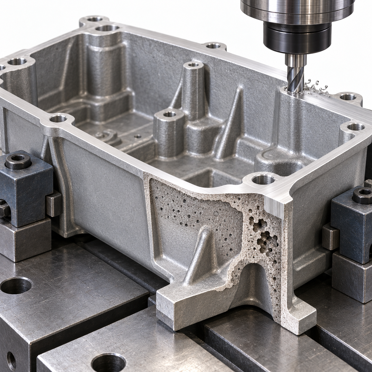
How can the machining stock allowance for a die-cast aluminum alloy be confirmed through casting measurement and first-article machining?
The machining stock allowance for die-cast aluminum alloy cannot be determined only during the CNC programming stage. Before mold release or mass production, the drawing should first identify the machined surfaces, rough and finish datums, minimum wall thickness after machining, hole-bottom thickness, and sealing or airtightness requirements. If the positions of locating bosses, datum surfaces, or bottom holes are unstable, simply increasing the stock allowance cannot correct the relationship errors among hole position, coaxiality, and sealing surfaces.
Confirming the machining stock allowance window for die-cast aluminum alloy through casting measurement
The first batch of castings should be measured using the actual clamping datums, including critical surfaces, datums related to hole positions, parting-line mismatch, warpage, and local wall thickness. Large flat surfaces should not be measured only at the center; check the edges and all four corners for local height differences as well. Use the measurement results to distinguish three types of problems: insufficient stock allowance causing incomplete cutting, excessive stock allowance causing insufficient remaining wall thickness, and overall offset caused by datum transformation. When necessary, coordinate-measuring-machine, gauge, or scan data can be combined to confirm the deviation distribution, but the measurement method must be consistent with the drawing datums.
Checking whether the machining stock allowance is truly appropriate after first-article CNC machining
After machining the first article, first confirm whether the functional surfaces have been completely and continuously cut and whether porosity, shrinkage cavities, cold shuts, or local defects have been exposed. Then check the minimum wall thickness after machining, hole positions, hole bottoms, flatness, threads, and assembly relationships. Sealing structures should also be tested for airtightness according to product requirements, while cosmetic surfaces should be checked for texture, tool marks, and local deformation. Single-fixture machining can reduce repeated positioning errors, but it cannot eliminate casting warpage, clamping deformation, tool wear, or measurement error.
- Drawing: Specify the machined surfaces, post-machining dimensions and tolerances, datum system, and minimum wall thickness.
- RFQ: Require the supplier to specify the casting-state datum, locating method, stock allowance window, and first-article measurement items.
- First-article report: Record casting deviations, post-machining dimensions, defect exposure, flatness, hole positions, and airtightness results.
- Mass-production correction: Adjust the stock allowance, clamping method, and toolpath based on measured distributions; do not turn a single rule-of-thumb value into a standard for all parts.
Common Questions About Machining Allowance for Die-Cast Aluminum Alloys
The machining allowance for die-cast aluminum alloys cannot be determined independently of the alloy, wall thickness, mold structure, datum chain, and first-article measurement results. The answers below are intended for drawing reviews and supplier communication and do not replace process validation for specific parts.
Is a machining allowance of approximately 0.2 mm suitable for all die-cast aluminum alloy parts?
No. Approximately 0.2 mm can only serve as an empirical reference in some design documents. In practice, the allowance must also account for die-casting dimensional variation, warpage, positioning errors, and the as-cast surface layer that needs to be removed. The minimum wall thickness after machining, hole-bottom thickness, and the risk of exposing defects must also be verified. The same value should not be applied uniformly to different features.
Should machining allowance for die-cast aluminum alloys be increased uniformly on sealing surfaces?
It should not simply be increased uniformly. Sealing surfaces must be machined continuously and completely while meeting flatness and airtightness requirements. However, an excessive allowance may cut into areas containing gas porosity or shrinkage porosity and may also result in insufficient local wall thickness. The appropriate range should be determined based on the distribution of blank deviations, the sealing structure, the clamping datum, and the minimum wall thickness after machining.
Why can an excessive machining allowance for die-cast aluminum alloys actually result in gas porosity or insufficient wall thickness?
The density of the surface layer and interior of a die casting may differ. After excessive material is removed, the cutting tool may enter areas with gas porosity, shrinkage porosity, or other concentrated defects. For thin-wall structures and transitions between thick and thin sections, excessive cutting can also reduce the effective wall thickness and increase the risk of deformation caused by cutting forces or clamping.
What should be measured during the first-article stage to confirm that the machining allowance is appropriate?
At a minimum, record the dimensions and warpage distribution of critical blank surfaces, and inspect the machined part for complete material removal, minimum wall thickness, hole-bottom thickness, hole position, flatness, threads, and sealing requirements. If the part has airtightness or appearance requirements, these should also be included in first-article acceptance. The measurement datums must correspond to the machining datums and drawing datums.
Key takeaways
- The lower limit of the machining allowance for die-cast aluminum alloys must cover blank dimensional variation, deformation, locating errors, and the as-cast surface layer that must be removed. The upper limit is constrained by minimum wall thickness, bottom thickness beneath holes, and the risk of exposing defects.
- Sealing surfaces, bearing bores, mounting holes, cosmetic surfaces, and thin-wall areas should not use the same allowance value. They should be evaluated separately according to their functions and datum chains.
- First determine the die-cast rough datum and the CNC precision datum, then work backward to determine the allowance. Simply increasing the allowance cannot correct hole-position, coaxiality, or flatness problems caused by unstable datums.
- Some design references mention a minimum machining allowance of approximately 0.2 mm, but this can only serve as an empirical starting point under specific conditions and cannot replace blank measurement and first-article verification.
- The drawing and RFQ should clearly specify the machined surfaces, post-machining dimensions, tolerances, datums, minimum effective wall thickness, defect acceptance criteria, and first-article inspection items.



