How much force should a brake pedal actually withstand?
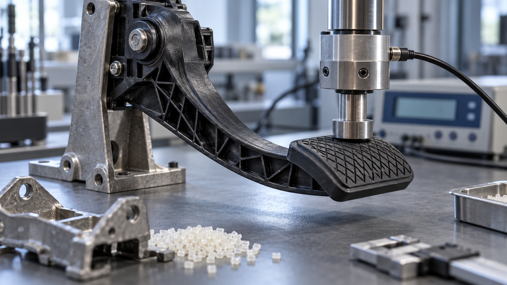
First, look at a test sequence that keeps many people awake at night: three vehicles performed consecutive emergency braking from 100km/h to 0, and on the second and third presses, the pedal bracket broke. The pedal force sensor installed on the vehicle recorded readings before and after the fracture—the first maximum pedal force was 1596N, the second was 1612N, and a peak of 4589N also appeared in the video.
What does 1596N mean? It is roughly equivalent to a 160 kg person standing directly on the pedal. The force a normal driver can apply in an emergency is usually only a few hundred newtons; breaking the pedal itself is something that should not happen. Qiu Jincao of the Chinese Society of Automotive Engineers put it bluntly: under no circumstances should a normal driver directly break the brake pedal by stepping on it. This is the bottom line for the brake pedal as a part—it is first a safety part, and only second a human-machine interface part that can be stepped on repeatedly.
So the question "how are brakes made, brake pedal" is really worth breaking down into three things. First, what force the pedal is designed to withstand—how exactly the standard is set. Second, how this force is achieved through materials and processes—the manufacturing of the brake pedal. Third, after it is made and installed on the vehicle, how those few millimeters of free play are adjusted. Let us follow these three lines below, starting by getting the force calculation clear.
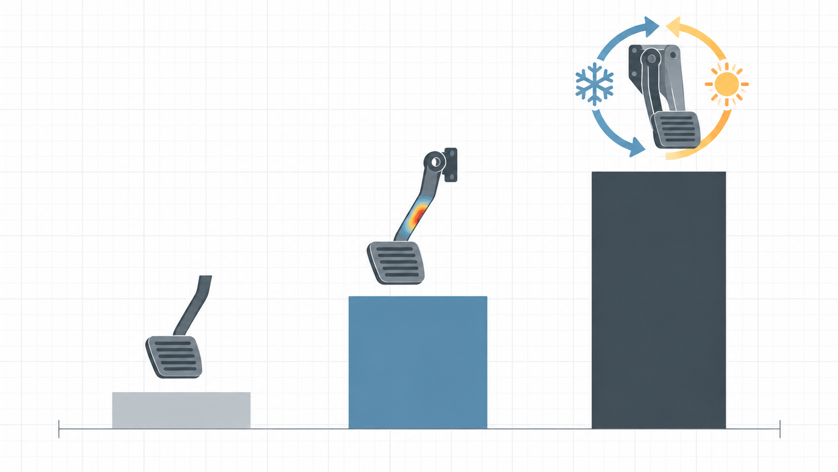
The force a brake pedal must withstand: the three-tier gap between national standards, industry standards, and automaker internal controls
The layer added by the industry-recommended standard: 1500N and 500,000 cycles
Automakers' internal controls are often a notch higher than industry standards
| Standard / Specification | Load requirement | Assessment target |
|---|---|---|
| Safety Specifications for Power-driven Vehicles Operating on Roads (mandatory) | Passenger car pedal force ≤500N; fully loaded ≤500N, unloaded ≤400N | Braking performance, not pedal strength |
| QC/T 788-2018 (recommended industry standard) | Longitudinal 1500±20N, hold for 5 seconds, 5 times front and rear, permanent deformation ≤5mm | Pedal static strength and deformation |
| QC/T 788-2018 working durability | Passenger cars 500±20N / commercial vehicles 700±20N, 500,000 cycles in each direction | Fatigue life |
| GMW15396 (2007 version, corporate specification) | Extreme load in the pressing direction 2700N | Extreme condition margin |
| Porsche MSB (Corporate Standard) | Fracture load 3000N, at three temperatures: -35°C / room temperature / 80°C | Fracture strength at extreme temperatures |
How brake pedals are made: materials, structure, and injection molding process
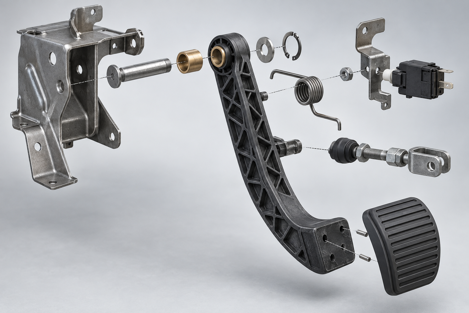
Hold the pedal assembly in your hand, and before rushing to talk about strength, first look at what it is assembled from. A passenger vehicle brake pedal assembly typically includes: the pedal arm (the main body that bears the bending moment from stepping), the pedal pad (the foot contact surface, mostly rubber or thermoplastic elastomer), the metal bracket (connecting to the vehicle body or pedal box), the pivot and bushing (rotating pair), the return spring, the brake light switch contact, and the connection point leading to the vacuum booster pushrod. Among these, the pedal arm and bracket are the mechanical protagonists, and they are also the locations most often named in fracture cases.
Material: PP or PA base material, with 30%–40% glass fiber
The mainstream industry approach is to use PP (polypropylene) or PA (polyamide, i.e., nylon) as the base material, adding about 30%–40% glass fiber, using short glass fiber reinforcement to improve strength, stiffness, and thermal stability. Once glass fiber is added, the material changes from "a plastic that can be injection molded" into "a composite that can be used as a structural part," which is the prerequisite for making brake pedals as plastic parts.
But glass fiber also brings an unavoidable contradiction: fibers orient along the flow direction in the melt stream, causing anisotropy in the molded part—high strength along the flow direction, weaker perpendicular to it. Even more troublesome is the weld area: where two melt streams meet, fibers struggle to entangle across the interface, and strength is often lower than that of the bulk material. The root of the pedal arm and the area near the pivot are precisely the cross-sections with the greatest bending moment. If the weld line falls here, it is equivalent to placing the weak point in the most stressed location.
From mold to finished product: the process chain for injection-molded pedal arms
Pedal arms are mostly injection-molded parts, and the process chain is roughly: mold design and gate position determination → injection molding → welding and inserts/assembly → dimensional and appearance inspection → mechanical sampling inspection. Each step affects whether the final part can withstand those several thousand newtons of force.
- Gate position: determines the melt flow path and where the weld line falls. If the gate is well placed, the weld line can avoid high-stress areas; if placed arbitrarily, the weak point remains at the root.
- Mold temperature and packing pressure: if mold temperature is too low and packing pressure is insufficient, the weld interface heals poorly and strength drops further; glass-fiber parts are especially sensitive to these two parameters.
- Inserts and assembly: metal pivot bushings and bracket connectors are fixed by insert molding or post-assembly, and the interface fit tolerance directly affects play and abnormal noise during stepping.
- Dimensional and appearance inspection: focus on weld line position, sink marks, warpage, and the coaxiality of the pivot hole—these are indirect indicators of subsequent mechanical performance.
- Mechanical sampling inspection: Perform sampling verification according to load cases to confirm batch consistency, rather than testing only the first article.
This process sounds similar to ordinary structural part injection molding, but the difference lies in verification density. For ordinary housing parts, sampling inspection only needs to check appearance and assembly. A brake pedal must be repeatedly verified according to load cases because it is a safety part—one poor weld, and it could mean one broken pedal. A common industry practice is to raise the glass fiber content to above 40%, or switch to long glass fiber to improve weld strength and fatigue safety margin; the specific ratio and process parameters need to be determined based on part geometry, load spectrum, and verification results, and cannot be copied directly.
If you are only making structural verification parts or small-batch trial production of a pedal assembly, the upfront investment in an injection mold is not small. Usually, CNC machining or 3D printing is first used for several rounds of shape and assembly verification, and then the mold is opened for injection molding, which can avoid detours. For this kind of on-demand manufacturing path, the rapid prototyping and injection molding capabilities pages provide more specific process descriptions.
Weld strength and fatigue margin: where injection-molded pedals are most likely to fail
When the previous sections break down injection-molded pedals, they all ultimately come down to the same location—the connection between the root of the pedal arm and the pivot. That is both the section with the greatest bending moment and often the place where material flows converge. The weld zone of glass-fiber reinforced plastic has lower strength than the bulk material, so the hardest step in "how brake pedals are made" becomes weld quality.
Why the weld location always falls on the most dangerous cross-section
In injection-molded parts, a weld is the interface formed when two melt fronts meet and merge in the mold cavity. The pedal arm is slender in shape, and its root must accommodate a pivot hole or metal insert. The mold often needs feeding from both sides or multiple points, and after the melt flows around the hole, it converges ahead—and this convergence point happens to be at the load-bearing cross-section near the pivot.
The weakness of the weld zone is not uniform: glass fibers are randomly oriented at the merging interface, the interfacial bonding between fibers and matrix is incomplete, and the interface temperature is also lower than that of the bulk material. As a result, the strength of the weld zone is usually lower than that of the bulk part. The industry generally believes the gap is significant, but the specific value depends on the material, gate, and process, and must be based on actual measurements. A brake pedal is a high-safety part, so this gap must be covered by structural redundancy and verification, rather than judged by whether it "looks thick enough."
The controllable variables affecting weld quality are very practical: gate position determines the melt convergence angle, and the sharper the convergence angle, the worse it is; mold temperature and packing affect the degree of interface healing, and when mold temperature is low, interface healing is insufficient; if injection speed is too fast, air will be trapped at the convergence point and weld marks will form. For molds making safety parts such as brake pedals, the gate and runner scheme usually must be determined together with fatigue margin during the DFM stage, rather than waiting until after trial molding to check appearance and then patch it.
Several realistic paths to improve weld strength and fatigue safety margin
A common industry practice is, first, to raise the glass fiber content to above 40%, using a higher fiber volume fraction to compensate for the strength loss in the weld zone; second, to switch to long glass fiber material, since long fibers overlap more fully at the interface, which is more favorable for fatigue safety margin. Both paths have costs: the higher the glass fiber ratio, the worse the melt flow, and the harder it is for the weld interface to heal; long fibers also place higher demands on the injection molding process and mold wear. So this is not a single-choice question of "the more glass fiber, the better"; it needs to be weighed together with pedal geometry, load direction, and verification conditions.
Another more robust approach is to make the weld location actively avoid the maximum bending moment cross-section: adjust the gate direction to push the melt convergence point to the middle of the pedal arm or a non-primary load-bearing area; or use a metal insert at the pivot position to bear local loads, turning the plastic part from "directly sheared" to "supported." Such changes will affect the mold structure and assembly process, and usually must be determined before opening the mold.
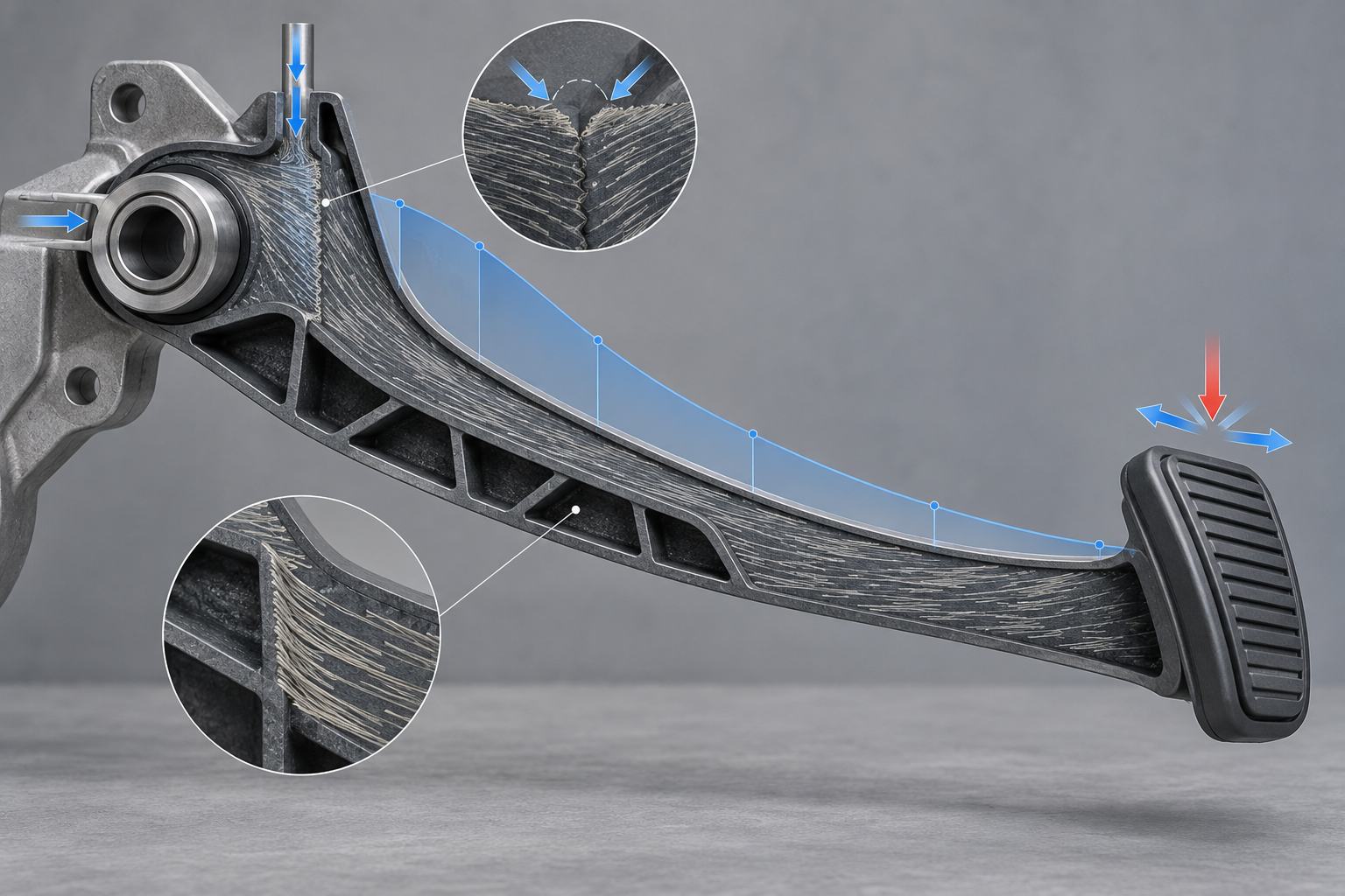
Forward pedaling and lateral pedaling: the two load conditions that verification must cover
When performing pedal strength verification, one easily overlooked difference is the loading direction. During forward vertical pedaling, force is transmitted along the cross-section of the pedal arm, mainly producing bending stress; but in real driving, the foot contact point is often offset inward or outward, forming lateral lever pedaling—the moment arm becomes longer, and the root of the pedal arm simultaneously bears bending and torsion, so local stress may be significantly higher than under forward conditions.
This is also why some vehicle pedals pass forward testing but expose risk during non-vertical pedaling. If the verification plan only performs a single forward loading, it is difficult to cover this condition. The automotive industry usually uses multi-directional loading: QC/T 788-2018 requires pedals to undergo durability tests in both front and rear loading directions, indicating that directional differences are an industry-recognized variable that must be covered. For the manufacturing side, this means the weld location and insert design must be evaluated according to the most unfavorable load direction, rather than optimized for a single forward condition.
If structural verification of such safety parts is required, the injection-molded part itself, inserts, and mold scheme often need to be prototyped and iterated together. For trial production of samples involving pedal arms, brackets, and pivots, the geometry and assembly can first be verified through the injection molding capabilities or rapid prototyping path, and then enter the mold and fatigue testing stage.
Change the material, and verification must be redone: what one recall reveals
Why "switching to another plastic" does not equal "an equivalent substitution"
Treat "design margin" as a verifiable quantity, not a slogan
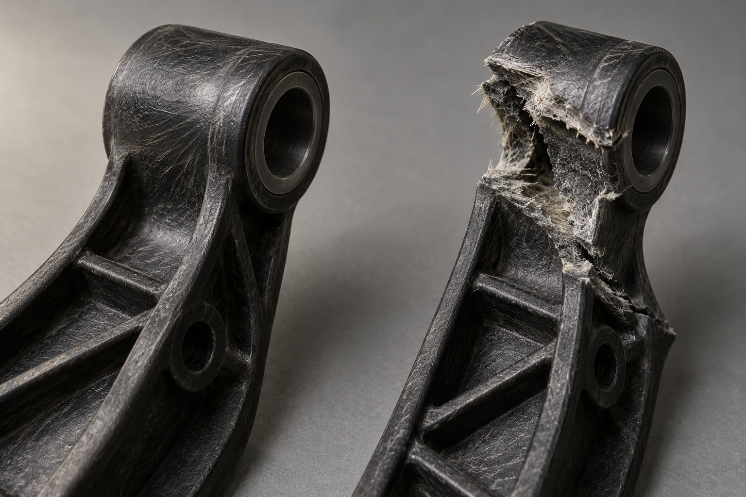
What brake pedal free play is: the assembly and adjustment behind 5–15mm
In the first small segment of pressing the brake pedal, the car has not actually begun to decelerate yet. This "empty press" distance is brake pedal free play—the amount of pedal travel from when the pedal begins to move to when the brake system actually builds hydraulic pressure and the caliper begins to clamp the brake disc. For passenger cars, free play in the industry usually falls in the range of 5mm to 15mm; the specific value is subject to the model's service manual, and not all cars use the same number.
Brake pedal free play is not an assembly error, but a deliberately left clearance. When the master cylinder piston fully returns, it must allow the oil passage in the cylinder to connect with the reservoir so that brake fluid can return and pressure can be released. If this travel is consumed, the piston cannot fully return, and residual pressure will keep the brake pads pressed against the disc, causing heat, drag, and faster pad wear while driving. Conversely, if too much clearance is left, the first part of the pedal press is all dead travel, braking response becomes slower, and in emergency conditions those few millimeters are distance.
Why free play becomes larger: from air resistance to wear
The most common reasons for excessive free play: air has entered the brake fluid, and air bubbles are compressible, so when the pedal is pressed they are compressed first before force is transmitted; brake pads have worn thinner, so the caliper piston must extend a longer distance before contacting the disc; improper pushrod adjustment, with the mechanical clearance between the pedal and master cylinder out of tolerance; failure of the master cylinder cup seal, with internal leakage causing slow pressure buildup. On the pedal, all these causes appear as "soft" and "long," but the handling methods are completely different—whether to bleed first or replace pads first must be distinguished by inspection.
Too little free play is likewise not a good thing. If the pedal has almost no dead travel, it means the pushrod is too tight or the piston is not returning properly, and braking will drag; after long driving, brake disc temperature rises, and in severe cases braking performance may be affected. This type of problem often appears during assembly after replacing the pump, replacing the booster, or maintenance, and belongs to the adjustment stage.
How to self-check: three things you can do while parked
- With the vehicle stationary and the engine off, press the pedal several times to release the vacuum in the booster, then lightly press the pedal and feel the length of the dead travel from the start to when it clearly "becomes hard."
- Compare pedal height: after pressing several times, the pedal height should remain basically stable. If it slowly sinks after being held down, it is most likely a seal or internal leakage problem, not free play itself.
- Open the engine compartment and check the brake fluid level, and also look at the replacement record—in the industry, brake fluid is usually replaced about every 2 years or 40,000 kilometers, subject to the model manual; after absorbing moisture, its boiling point drops, which will amplify air resistance problems.
To be clear, adjusting the pushrod length is a repair operation that involves the interface between the master cylinder and the booster. The structure varies greatly between vehicle models, so it must be performed according to the repair manual for the corresponding model. Twisting the pushrod yourself without data and tools can easily eliminate the free play, and instead create drag. The value of self-inspection lies in determining "whether to go to the shop," not in replacing adjustment.
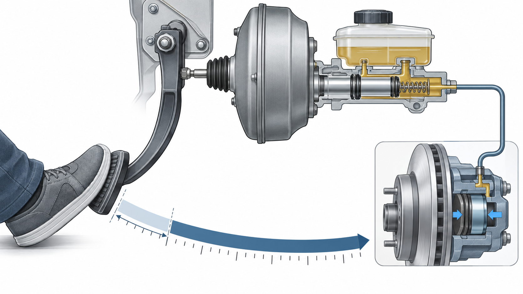
Put free play back into the context of the entire chain: it is actually an output of manufacturing and assembly consistency. The pedal's pivot clearance, pushrod length, master cylinder piston return position, and brake pad thickness—any deviation in any one of these will show up in these few millimeters. Precisely for this reason, the dimensional tolerances of the pedal assembly and how fully it is assembled are far more important than they appear.
Why repeatedly press the pedal after installing it: the final step from assembly to building pressure
After replacing the brake pads, the mechanic sits in the car and presses again and again until the pedal becomes firm before stopping. This action looks like a ritual, but it is actually the final step in the brake pedal manufacturing and assembly chain: if it is not pressed into position, braking force cannot be established. How the brake pedal is made and installed must ultimately come down to the feel of this press.
The reason is that a gap remains between the new pads and the brake rotor. During replacement, the caliper piston is pushed back into the cylinder bore, and a free travel of a few tenths of a millimeter to one or two millimeters may appear between the pads and the rotor. Repeatedly pressing the pedal uses hydraulic pressure to push fluid out of the master cylinder, pushing the piston back against the back of the brake pad so that the pad contacts the rotor. When the pedal feels pressurized and no longer spongy, it means this gap has been taken up and system pressure has been established. If it is still soft after many presses, it is usually not a pad problem, but air in the lines or insufficient brake fluid.
The brake pedal is only the force input end
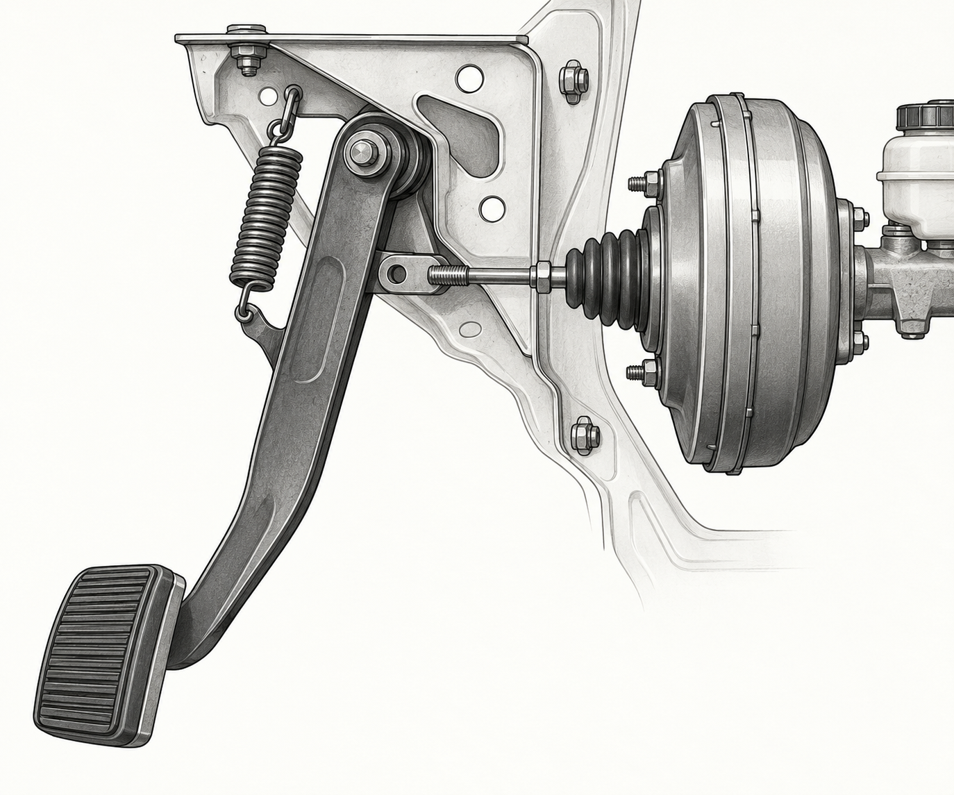
From the perspective of the entire braking chain, the pedal assembly is responsible for one thing: transmitting foot force downstream. The force path is pedal arm—pushrod—vacuum booster—master cylinder—lines/hoses—caliper piston—brake pads—brake rotor. The pedal itself does not generate braking force; it only determines how much force is input and how much travel is used. Therefore, if the pedal is soft or the travel becomes longer, the problem may lie in any link in the chain, not necessarily the pedal.
This also explains why the pedal's structural stiffness and installation stiffness are equally safety-critical indicators. If the pedal arm or bracket visibly deforms elastically under load, the feel is "spongy when pressed," and the driver will unconsciously increase pedal force. The fusion zone and the cross-section near the pivot discussed in the previous section are precisely what must maintain their shape under this repeated loading.
When the pedal is soft, troubleshoot in order
Here is a practical order for judgment, to avoid replacing parts right away:
- First check the brake fluid: see whether the level is below the minimum, whether the color has turned black, and whether it has been changed recently. Brake fluid is hygroscopic, and the industry generally recommends replacement about every 2 years or 40,000 kilometers, subject to the vehicle manual.
- Then check for air: if the fluid level is normal but the pedal is soft and can be pressed to the floor, it is most likely air in the lines, and bleeding is needed in the order specified for the vehicle model.
- Then check the pads and rotor: pads worn to the limit, a scored rotor surface, or uneven thickness will all lengthen travel.
- Finally check the pushrod and free play: improper pushrod adjustment will make the free travel too large; this item is a repair operation and must be performed according to the vehicle manual. Do not adjust it randomly by feel.
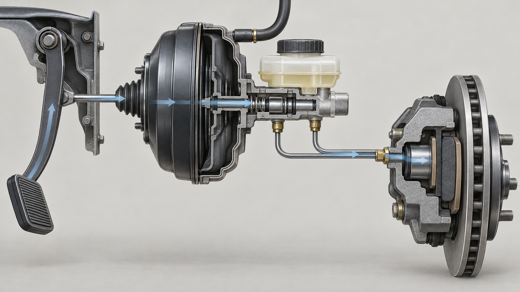
Remember this order, and you can understand why "repeatedly pressing after replacing pads" is not optional: it returns the piston travel to position during the assembly stage, bringing the system back to a state where pressure can be built. Only then does brake pedal free play (typically 5–15 mm for passenger cars) have a stable baseline. Excessive brake pedal free play is often directly related to fluid, air, pads, and the pushrod, rather than a broken pedal body itself.
For those who make pedals or pedal-related structural parts, there is a simple lesson here: the feel after assembly is the sum of all preceding processes. Only when injection-molded parts have stable dimensions, the fusion zone is strong enough, and the bracket hole positions and pivot coaxiality are good can the force-travel curve of pressing the pedal be repeatable; otherwise every press differs slightly, and the driver's expectation of braking force will be disrupted. This is also why, during prototyping and small-batch stages, pedal-type parts should verify installation point stiffness, pushrod interface position, and return spring preload together, rather than just testing a single fracture load and calling it done.
Frequently Asked Questions (FAQ)
The following questions are the ones most likely to trip you up after reading the previous sections: how to read the standard numbers, how much fiberglass to add, whether you can adjust the free play yourself, and how to choose between plastic and metal pedals. The answers give boundaries, not promises.
The national standard says 500N and QC/T 788 says 1500N—which one actually counts as the strength requirement for a brake pedal?
The two govern different things. The 500N in the mandatory national standard "Safety Specifications for Power-Driven Vehicles Operating on Roads" (the upper limit of pedal force at maximum braking efficiency for passenger cars, ≤500N when fully loaded and ≤400N when unloaded) constrains braking performance—how much force it takes to stop the vehicle. It does not directly specify how much force the pedal itself can withstand. QC/T 788-2018 is a recommended industry standard that requires applying a longitudinal force of 1500±20N to the brake pedal, holding it for 5 seconds, and repeating it 5 times front and back, with no cracks or damage and a permanent deformation of ≤5mm after the test. That is the test method for the structural strength of the pedal. Note that QC/T is a recommended standard, not mandatory; internal corporate controls are often higher—for example, the 2007 version of GMW15396 sets the extreme load in the pedal depression direction at 2700N, and the Porsche MSB platform requires a fracture load of 3000N. When reading a standard, first check its scope of application and version year.
Does a higher fiberglass ratio make the brake pedal stronger?
Not necessarily proportional. The industry mainstream is PP or PA base material with 30%–40% glass fiber added to improve strength, stiffness, and thermal stability. But the weak point of glass-fiber parts is often the weld line area—fiber orientation is unfavorable where the material flows converge, so strength is lower than that of the bulk material. Raising the ratio above 40%, or switching to long glass fiber, can improve weld-line strength and fatigue safety margin, but higher fiber content also changes flowability, surface quality, and anisotropy, requiring new mold and process validation. So "how much to add" is not just about the number; it depends on weld-line location, load direction, and fatigue conditions.
Can I adjust the brake pedal free play myself?
You can self-check it, but adjusting the push rod is a repair operation, so it is recommended to follow the vehicle model's service manual. Passenger car free play is usually 5–15mm, referring to the pedal travel from the start of depression until the braking system actually generates braking force. You can self-check as follows: after parking and shutting off the engine, first press the pedal a few times to release the boost, then slowly depress the pedal, feel the initial dead travel, and at the same time observe changes in pedal height and check the brake fluid level. If the free play becomes noticeably larger, common causes are air in the brake fluid, worn brake pads, improper push rod adjustment, or failure of the master cylinder cup seal; if it is too small, there may be brake drag, heat, and accelerated pad wear. Brake fluid is usually recommended to be replaced every 2 years or 40,000 km, subject to the vehicle model's manual.
How do I choose between plastic and metal pedals?
It depends on the application and production volume. The pedal arms of mass-produced passenger cars are mostly glass-fiber-reinforced engineering plastic injection molded parts. Their advantages are high integration, light weight, and high molding efficiency; the cost is that weld-line areas and temperature sensitivity need to be covered by design margin and validation—the recall case where switching from nylon to polypropylene caused reduced strength is a lesson. Metal brackets, pivots, and other load-bearing parts are still commonly metal. For small-batch trial production, modification, or validation samples, CNC-machined metal pedal arms or 3D-printed structural parts are more flexible, but note that the fatigue performance of these processes is not equivalent to that of mass-produced injection molded parts, and sample results cannot directly replace mass-production validation.
Why do forward and side pedaling give very different results during testing?
Because the form of loading is different. Under forward vertical pedaling, the pedal arm mainly undergoes bending, and the cross-sectional stress distribution is relatively controllable; side or angled pedaling is equivalent to adding a lever at the base of the pedal arm, superimposing bending moment and torque, and stress concentration is likely near the pivot. The fracture risk in many vehicle models occurs precisely at the base of the pedal arm under non-vertical pedaling. Therefore, validation conditions must cover forward, side, and different temperature conditions (such as -35°C, room temperature, and 80°C). Passing a test in a single direction does not mean that all pedaling methods are safe in actual use.
Key takeaways
- The mandatory national standard specifies "how much force is needed to stop the car" (for passenger cars, pedal force at maximum braking efficiency ≤500N), and does not directly specify how much force the pedal itself can withstand; only the industry-recommended standard QC/T 788 gives structural requirements such as 1500N held for 5 seconds, no cracks, and permanent deformation ≤5mm.
- Mainstream brake pedal arms are injection-molded parts made of PP or PA with 30%–40% glass fiber. The strength of the glass fiber weld area is weaker than that of the body, so sufficient fatigue safety margin must be retained. This is also the core contradiction in designing mold gates and weld locations.
- Material changes must be revalidated: there was once an automaker that changed the bracket material from nylon to polypropylene, after which peak strength decreased, creating a risk of fracture at the pedal pivot position and leading to a recall.
- Passenger car pedal free play is usually 5–15mm. Too much (air in the brake fluid, worn brake pads, improper pushrod adjustment) or too little will affect braking, and it is an item that must be confirmed after assembly.



