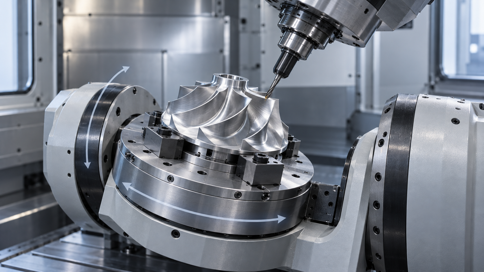
A hypothetical thin-walled pump housing: why the 3-axis approach gets stuck here
Where exactly is the "five" in 5-axis: the motion relationship of three linear axes plus two rotary axes
Breaking 5-axis down, it means three linear axes plus two rotary axes participating in cutting simultaneously. X, Y, and Z are responsible for the position of the tool tip in space, while A, B, and C are responsible for the orientation of the tool or workpiece. A common convention is: the A axis rotates around the X axis (forward/backward tilt), the B axis rotates around the Y axis, and the C axis rotates around the Z axis. But this cannot be treated as an iron law—under different manufacturers and different structures, the naming and positive directions of rotary axes may change, so before programming you must check the machine manual and machine coordinate system definitions, otherwise the direction of the G-code output by post-processing will be reversed.
3-axis can only keep the tool axis always parallel to Z. Once a curved surface has side walls, undercuts, or deep cavities, the tool holder will hit the wall, or a ball nose tool can only contact at the tool tip point, resulting in poor cutting conditions. The value of 5-axis lies in letting the tool axis orientation follow the surface normal: during side milling, the tool's side edge stays against the curved surface, giving uniform linear speed and low residual height; in deep cavities, the tool holder is tilted by an angle to avoid interference. This is not "5-axis is more advanced," but rather that the two extra rotary degrees of freedom open up accessibility and cutting angles.
| Axis | Type | Common definition | Typical function |
|---|---|---|---|
| X | Linear | Table/spindle moves along X | Positioning in the length direction |
| Y | Linear | Table/spindle moves along Y | Positioning in the width direction |
| Z | Linear | Spindle moves up/down along Z | Depth and tool axis direction |
| A | Rotary | Usually around the X axis | Workpiece/spindle tilts forward/backward to machine side faces |
| B | Rotary | Usually around the Y axis | Workpiece/spindle tilts left and right |
| C | Rotation | Usually around the Z axis | Rotary indexing, multi-face machining |
Synchronized simultaneous motion relies on the closed loop between the controller and the drives
Five axes moving "simultaneously" does not mean each of the five axes moves independently. The controller is responsible for real-time solving of multi-axis interpolation, ensuring that linear axes and rotary axes coordinate on the same time base; the drives execute motion interpolation, and the encoders feed the actual position back for closed-loop correction. Any lag in one feedback path, mismatched gain, or excessive backlash on a rotary axis will leave traces of overcut or undercut on the simultaneous-motion trajectory. This is also why five-axis machining places one grade higher demands on mechanical precision, calibration, and temperature control than three-axis machining—the error no longer comes only from a single axis, but from the synchronization relationship between axes.
Machine structure determines reachability and rigidity: how to choose Head/Head, Head/Table, Table/Table
The conventional recommendation is: for heavy parts and large contours, choose table rotation; for light parts and complex surfaces, choose spindle head tilting. This rule holds for most small and medium parts, but it fails on oversized, overweight, or slender parts—table load capacity, moment of inertia, and thermal deformation become bottlenecks, and tilting accuracy instead decreases. Below, the common structures are broken down one by one.
Three basic structures: whether the tilting is placed on the spindle or the table
According to the load-bearing position of the two rotary axes, they are commonly divided into three categories: spindle head/spindle head (Head/Head), spindle head/table (Head/Table), and table/table (Table/Table). The trunnion type usually has the A axis around X and the C axis around Z, and belongs to a variant of Head/Table or Table/Table; the rotary-rotary type commonly has the B axis around Y and the C axis around Z. Naming should be based on the machine tool manual, as different manufacturers may be inconsistent.
| Head/Head | Both rotary axes are at the spindle end | Small and medium complex surfaces, mold cavities, impellers | When the part is heavy and the table does not move, spindle tilting rigidity decreases as overhang increases; chatter is likely under high cutting force conditions |
| Head/Table | One axis on the spindle, one axis on the table | Medium-sized boxes, multi-face feature parts, housings with undercuts | Table load capacity and moment of inertia become the upper limit; positioning accuracy decreases when oversized parts rotate |
| Table/Table (including trunnion type) | Both rotary axes are on the table | Heavy parts, large contours, frame parts requiring multi-face machining | When the part is overweight or eccentric, servo load and thermal drift intensify; slender parts are prone to deformation when rotated |
| Rotary-rotary type | Dual rotation of the table | Composite features of bodies of revolution, surfaces requiring continuous five-axis simultaneous motion | Clamping height is limited; tool reachable angles are constrained by structural geometry |
When "choose table rotation for heavy parts" fails
Detection signals: after the part is mounted on the table, the rotary axis current rises noticeably, backlash increases, periodic chatter marks appear on the machined surface, or the first article's position tolerance in the rotary direction is out of tolerance. At this point, continuing to follow the conventional recommendation will cause yield to drop. A safer choice: split the part into modules that can go on a small table, or switch to a floor-type structure, indexing fixture, or multiple setups with a unified datum; for oversized parts, first confirm the upper limits of table load capacity and moment of inertia before discussing five-axis simultaneous motion.
From CAD to G-code: why the programming and simulation step is the most prone to failure
The conventional approach is: take the 3D model, hand it to CAM to generate toolpaths, post-process to output G-code, and cut on the machine. Doing this for three-axis machining is usually no problem. Five-axis machining extends this chain by two links—post-processing and machine simulation—and these two places happen to be what beginners most often skip and what experienced operators least dare to omit. Failures rarely occur at the moment of cutting; they mostly occur in file handoff and coordinate system definition.
The seven nodes of the process chain: which is the most fragile
On this chain, post-processing is the most easily underestimated link. The same cutter location file, when switched to a five-axis machine with a different structure, requires the post-processor to be redone; directly applying an old post-processor, if the rotary axis direction or pivot length does not match, will at best cause overcutting and at worst crash the spindle. The judgment signal is very direct: in simulation, the rotary axis motion is opposite to expectation, or the tool tip trajectory shows steps at reversal points—most likely a post-processor parameter issue, not a CAM strategy issue.
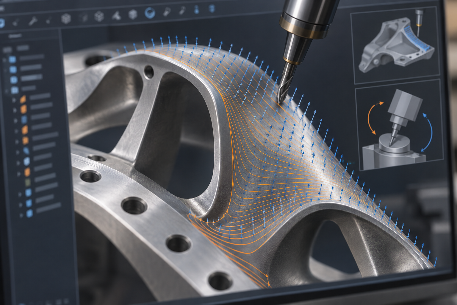
A safer choice is not to buy more expensive CAM, but to treat simulation and first-article inspection as mandatory processes, and not skip them just because the delivery deadline is tight. A more conservative programming strategy (for example, using more side milling and less extreme tilt angles) will slow the cycle time, but the first-article success rate will be higher. Conversely, if the part is simple enough that three-axis machining plus one flip can finish it, the investment in five-axis programming is hard to amortize—this itself is a boundary.
Boundary conditions where conventional practice fails: thin walls, deep cavities, difficult-to-cut materials, small batches
"Fewer setups with one clamping means less accumulated error, so 5-axis is more stable"—this statement holds for most medium-to-thick-walled parts with moderate tolerances. But applying it as a general rule to thin walls, deep cavities, difficult-to-cut materials, and small batches often backfires: setups are fewer, but deformation, chatter, tool holder interference, and programming amortization become the main contradictions. Below, we break it down item by item following "common practice—failure boundary—detection signal—more stable choice."
Thin-walled parts: rigidity issues don't disappear just because there are fewer setups
The common practice is "go 5-axis, one setup, finish-mill all faces." Exception: for frame parts where wall thickness approaches the tool diameter and overhang is large, the tool posture change during 5-axis tilting alters the direction of cutting force, the thin wall yields at the location of lowest normal stiffness, springs back after the tool exits, and both wall thickness tolerance and flatness go out of spec together. Detection signals: wall thickness difference between mid-wall and root exceeds half the drawing tolerance, flatness rebounds on re-measurement after finish milling, regular chatter marks appear on the surface. More stable choice: leave 0.3–0.5 mm allowance for semi-finishing first, use supports or low-melting-point filler/plaster backing on the end face, then finish mill; if necessary, switch to symmetric material removal and layered light cuts. If the drawing does not specify process bosses or backing requirements, confirm with engineering whether they are allowed.
Deep cavities: 5-axis can tilt, but that doesn't mean the tool holder can get in
The common practice is "use 5-axis tilting to avoid interference and mill the deep cavity inner walls in one pass." Exception: when the cavity depth-to-opening width ratio is large and the bottom corner R is small, tilting causes the tool holder or spindle nose to hit the opposite wall first, and the reachable angle is locked out. The commonly cited length-to-diameter ratio experience value in the industry is relatively stable within 3–4 times; beyond that, the probability of tool deflection, chatter marks, and edge chipping rises noticeably, and the specific limit must be confirmed by simulation based on the actual tool holder geometry. Detection signals: simulation reports interference, tool deflection marks appear at a fixed depth in actual machining, surface immediately improves after switching to a shorter holder for the same diameter tool. More stable choice: shorten tool overhang, use an extension holder only for roughing in layers, switch finishing to a small-diameter ball nose tool with tilt capability and accept more passes; the match between cavity bottom R and tool radius must be confirmed at the drawing stage.
Difficult-to-cut materials: tilting maintains cutting width, but cooling and thermal drift must keep up
The common practice is "for titanium and high-temperature alloys, use 5-axis tilting so the ball nose tool cuts on the effective radius, keeping cutting width stable and tool life long." Exception: these materials have poor thermal conductivity, coolant struggles to reach the cutting zone after tilting, and combined with long continuous cutting programs, thermal drift of the spindle and workpiece eats away the accuracy gains from tilting. Detection signals: unidirectional dimensional drift after two hours of continuous cutting, built-up edge on the tool tip, worsening Ra. More stable choice: high-pressure through-spindle cooling, segmented tool withdrawal for rest, and if necessary on-machine measurement for compensation; separate roughing and finishing, and let the machine thermally stabilize before finishing. Whether 5-axis is worth it depends on whether the part truly has curved surfaces or undercuts that require tilting to reach, not on the material itself.
Small batches: the threshold where programming and fixturing amortization no longer pays off
The common practice is "go 5-axis even for small batches, to save on setups." Exception: when the quantity is only a few pieces and the geometry is a simple prismatic part, the labor hours for 5-axis CAM multi-axis strategies, post-processing, and collision simulation may cost more than 3-axis with multiple setups, and first-article risk is higher. Detection signals: programming and simulation account for a noticeably higher share of the quote than cutting hours, repeated toolpath revisions on the first article. More stable choice: first validate with 3-axis plus dedicated soft jaws or angle plate fixturing, and only switch to 5-axis when undercuts or multi-face positional tolerance requirements truly exist; write the datum and key positional tolerances into the technical agreement to reduce back-and-forth.
| Scenario | Common rule | Failure boundary | Detection signal | More stable choice |
|---|---|---|---|---|
| Thin-walled frame | One-setup finish milling of all faces | Wall thickness ≈ tool diameter, large overhang, tilting changes cutting force direction | Mid-wall to root wall thickness difference exceeds half tolerance, flatness rebounds | Leave allowance for semi-finishing, backing support, symmetric layered light cuts |
| Deep cavity narrow opening | Tilt to avoid interference and mill inner walls in one pass | Large cavity depth/opening ratio, tool holder or nose interference | Simulation reports interference, tool deflection marks at fixed depth | Shorten overhang, layered extension holder for roughing, small-diameter ball nose for finishing |
| Titanium/high-temperature alloy | Tilt to maintain effective cutting width | Cooling hard to reach, long-program thermal drift | Unidirectional dimensional drift after continuous cutting, built-up edge | High-pressure through-spindle cooling, segmented rest, on-machine measurement compensation |
| One piece/few pieces | Go 5-axis even for small batches | Programming and simulation hours exceed cutting hours | High programming share in quote, repeated toolpath revisions on first article | First validate with 3-axis + dedicated fixturing, switch to 5-axis only if truly needed |
This table is not for judging "whether it can be done," but for judging "whether it is worth doing by conventional practice." When a part hits two or more boundaries at the same time, it is recommended to first follow the more stable choice, then evaluate whether to upgrade. If the drawing does not specify that backing, process bosses, or segmented machining are allowed, do not add them on your own by default; confirm with engineering.
Inspection and acceptance: high positioning accuracy does not equal a qualified part
The easiest pitfall when flipping through catalogs is to treat the machine tool's positioning accuracy and repeatability as the criterion for part qualification. Those are equipment specifications: measured under no load, at constant temperature, with single-axis jogging. Part qualification depends on drawing requirements such as profile tolerance, position tolerance, and surface roughness, with tool, fixture, thermal deformation, and rotary axis errors in between. In the industry, common high-performance configurations have a nominal positioning accuracy on the order of ±0.001 mm, standard configurations on the order of ±0.005 mm, and repeatability of about ±0.0005 to ±0.002 mm—this is a typical configuration range; the specific values are subject to the machine's actual measurement report and cannot be directly applied to part tolerances.
Inspection logic: define the datum first, then discuss the method
The conventional approach is to send the first article to a CMM and run through a full-dimensional report. But there are two boundary conditions: first, if the datum itself is not clearly defined, the measurement results cannot be aligned with the drawing—this is especially easy with multi-face feature parts, because the datum will drift under different clamping states; second, if a thin-walled part is measured in the free state, it springs back after unclamping, and the measured dimensions do not match the assembled state. A safer choice: write the datum, inspection state (free state or constrained state), and whether sampling or full inspection into the drawing or technical agreement, and do not leave it to the inspector to judge on site.
On-machine measurement is suitable for process compensation: after measuring the deviation, write it back to the tool offset to suppress thermal drift and the accumulation of tool wear. But it cannot replace final inspection—when the machine coordinate system and the measurement datum are inconsistent, on-machine data can only be used for trends, not as a basis for acceptance. A typical signal of insufficient rotary axis accuracy is: when the same feature is repeatedly measured at different A/C angles, the position dispersion is significantly greater than in the linear axis direction; the signal of thermal drift is that after machining for a period of time, the profile tolerance slowly drifts in one direction, and after stopping and cooling, measurement returns to the original value.
| Using machine tool positioning accuracy to infer part tolerances | Thin walls, overhangs, difficult-to-cut materials | Profile dispersion, large Ra fluctuation | Leave process allowance according to drawing tolerances, measure the first article with a CMM |
| Release the batch once the first article passes | Long-time cutting, continuous machining | Dimensions drift in one direction over time | Use on-machine measurement for process compensation, perform periodic sampling |
| Measurement in the free state | Thin-walled, springback-prone parts | Dimensions change after unclamping | Agree on constrained-state measurement, or specify the measuring fixture |
| Measure only in the linear axis direction | Multi-angle faces, features involving rotary axes | Position dispersion at different angles | Supplementarily measure rotary axis positioning and repeatability |
The procurement implication is just one sentence: clearly writing the inspection method, datum, and sampling ratio is more useful than writing "accuracy meets standard" in the contract. Five-axis reduces the number of setups and indeed lowers the number of datum transfers, but the premise is that the first-article datum and the acceptance datum are clearly defined—otherwise the benefit of a single setup will be offset during acceptance by disputes over re-clamping.
When not to go five-axis: a judgment checklist for engineering and procurement
The previous sections all discussed what five-axis can do. This section goes the other way: which parts become more expensive, slower, and less stable when run on five-axis. The conventional advice is "go five-axis if the geometry is complex," but this rule fails in scenarios such as low tolerances, no undercuts, and single-piece prototypes—the extra money spent does not buy corresponding accuracy or cycle-time benefits.
Ask these five questions first, then decide whether to go five-axis
- Can three-axis with multiple setups meet the requirements? If all faces of the part are planar and the hole system has positional tolerances on the order of ±0.05 mm, three-axis plus a dedicated fixture is often sufficient, and the programming investment for five-axis cannot be recovered.
- Are there real undercuts, deep cavities, or continuous curved surfaces? If there are no undercuts and the curved surfaces are only simple chamfers, the accessibility advantage of five-axis cannot be used.
- Can the batch size amortize programming and fixturing? For a single piece or a prototype of three to five pieces, CAM multi-axis strategies and post-processing account for a high proportion of labor hours, and the unit price will be significantly pushed up.
- Does the material require tool orientation to maintain cutting stability? For difficult-to-cut materials such as titanium alloys, superalloys, and high-silicon aluminum, five-axis can maintain radial width of cut and cooling, and the benefit is real; for ordinary aluminum alloy, the significance is limited.
- Does the site have post-processing, collision simulation, and skilled operators? Buying the equipment does not mean it can be produced; post-processing errors and interference are common failure points.
If two or more of the five questions are answered "no," you should usually first evaluate three-axis with multiple setups, or switch to another process (sheet metal bending and welded assembly, casting followed by finishing, hand-model duplication to verify the shape). This is not to say five-axis is bad, but rather that the benefit of five-axis comes from "solving complex geometry in one setup"; when the geometry is not complex, the benefit disappears.
| Driver | Common industry magnitude | When it becomes a burden |
|---|---|---|
| Equipment and maintenance | Five-axis machining centers commonly range from USD 200,000 to 800,000, with higher-end configurations costing more | When orders are intermittent and equipment utilization is low, depreciation gets spread onto each part |
| CAM programming | Multi-axis strategies, post-processing, and simulation take far more man-hours than 3-axis | Least cost-effective for one-offs, small batches, and simple geometry |
| Skilled operators | Commonly requires a 3–6 month training period in the industry | Stability drops with high staff turnover and night-shift scheduling |
| Fixtures and inspection | Dedicated fixtures + CMM first-article inspection | Unnecessary for low-tolerance parts, turning the investment into pure cost |
Putting the above points together: for simple prismatic parts, low tolerances, one-off prototypes, and multi-face features without undercuts, prioritize 3-axis or alternative processes; only when at least one of geometric complexity, material difficulty, or tolerance requirements truly stumps 3-axis does the 5-axis math work out. For a specific part, you can first send the drawing to CNC machining capabilities to compare against the process scope, then decide whether to go the 5-axis route, avoiding paying for accessibility you don't need.
FAQ: Is 5-axis suitable for small batches, is accuracy necessarily higher, and where is programming difficult
The previous sections broke down the boundary conditions in some detail; here we focus on answering the questions purchasing and engineering ask most often. All answers come with preconditions: 5-axis is not a universal solution, nor is more expensive always more correct.
Is 5-axis suitable for small batches? Is it worth it for one-off or a few parts?
It depends on part geometry. If 3-axis requires three to four setups and each setup requires re-establishing the datum, small batches are actually a stronger case for 5-axis—fewer setups save both accumulated error and setup time. But if the part is a simple prismatic piece with loose tolerances, 5-axis programming and fixture amortization won't pay off, and 3-axis, sheet metal, or 3D printing may be more cost-effective. Decision signals: only when setups exceed three, or undercuts and multi-face features exist, does it enter the candidate range for 5-axis.
Is 5-axis machining accuracy necessarily higher than 3-axis?
Not necessarily. Machine positioning accuracy and repeatability are equipment specifications; whether a part passes depends on profile tolerance, position tolerance, and surface roughness. The advantage of 5-axis lies in reducing datum transfer errors through a single setup, but if rotary axis accuracy is insufficient, thermal drift is uncompensated, or post-processing is wrong, the result may be worse than a stable 3-axis solution. Common high-performance configurations in the industry have positioning accuracy at the ±0.001 mm level and standard configurations at the ±0.005 mm level, with repeatability around ±0.0005–0.002 mm, but these are only typical ranges; refer to the machine specifications and acceptance report for specifics.
Where exactly is 5-axis programming difficult? How much does it differ from 3-axis?
The difficulty is not in a single toolpath, but in tool orientation control under multi-axis simultaneous motion, post-processing, and collision simulation. 3-axis only needs to consider three-directional feed, while 5-axis must also handle rotary axis travel, interference between tool holder and workpiece, and post-processing differences across machine structures. Choosing the wrong CAM strategy (side milling, constant scallop milling, compound drilling) can at best leave obvious tool marks on the surface, and at worst cause a crash. When programming capability is insufficient, conservative strategies stretch cycle time, offsetting the efficiency advantage of 5-axis.
What makes 5-axis machining centers expensive? How should ROI be viewed?
Cost drivers are mainly equipment and maintenance, CAM programming, skilled operators, and training periods. Common industry price ranges are about $200,000–$800,000, with high-end configurations possibly exceeding $1 million, but this is only a reference and excludes fixtures, tooling, and software. Payback period depends on order structure and equipment utilization; a commonly cited figure is 2–3 years, but when orders are insufficient or parts are unsuitable for 5-axis, that number does not hold. Before purchasing, confirm: does the part geometry truly require 5-axis, rather than buying it just to "have this machine."
What should be noted in inspection and acceptance of 5-axis machining?
Write the inspection methods, datums, and acceptance criteria into the drawing or technical agreement. For first articles, it is recommended to use a CMM to measure key profiles and positional features; in batch production, use CMM sampling or in-machine measurement for process compensation. Note the distinction between equipment accuracy and part accuracy: high machine positioning accuracy does not mean the part passes. Insufficient rotary axis accuracy and thermal drift often surface after long machining runs, so inspection should be performed under stable conditions and ambient temperature recorded.
Key takeaways
- First determine whether the part has undercuts, deep cavities, or multi-face features, then decide whether to use 5-axis; "good-looking curved surfaces" alone is not a reason.
- The benefit of 5-axis comes from reducing the number of setups, at the cost of programming, simulation, and fixturing investment; for small batches, calculate the amortization first—do not assume 5-axis is more economical.
- For thin-walled parts, do not use 5-axis for "high-speed light cutting"; first confirm fixture support and rotary axis rigidity, otherwise vibration will be amplified rather than reduced.
- The prerequisite for using 5-axis on difficult-to-cut materials is that the tool can maintain a stable cutting width and adequate cooling, otherwise changing axes just changes the direction in which the tool deflects.
- During acceptance, write profile tolerance, position tolerance, and surface roughness into the inspection plan; high machine positioning accuracy does not mean the part is qualified.



