How Hydraulic Guillotine Shearing Machines Affect Sheet Metal Part Dimensional Accuracy, Burrs, and Deformation
When sheet metal parts have inconsistent lengths after shearing, excessively large cut-edge burrs, or slight warping in thin sheets, the problem is usually not simply that the “machine lacks sufficient accuracy.” The processing result of a hydraulic guillotine shearing machine depends on a complete chain: back-gauge positioning—hold-down securing—shearing by the upper and lower blades—worktable support—first-article inspection. Instability at any point can carry deviations into subsequent bending, welding, or assembly.
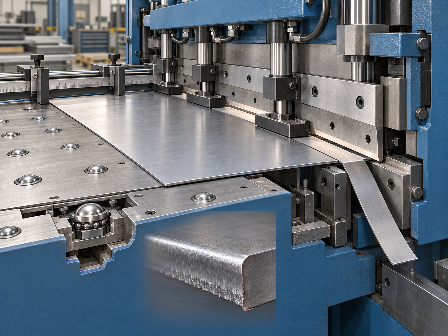
During operation, the back gauge first determines the cutting length, and the sheet must be fully seated against the positioning surface; the hold-down device prevents sheet slippage; the upper and lower blades separate the material through relative motion; and the worktable and auxiliary supports help keep thin sheets stable. Blade clearance, cutting-edge condition, and rake angle affect cross-sectional quality, while insufficient back-gauge parallelism, mechanism clearance, or sheet contact is more likely to cause dimensional drift.
Quality Troubleshooting for Hydraulic Guillotine Shearing Machines Should Trace Parameters Back from the Results
- Length or width deviations: First check the back-gauge setting, cleanliness of the positioning surface, sheet contact, and parallelism; do not rely solely on the value shown on the controller.
- Burrs and tearing steps: Check the shearing clearance, blade wear, chipped cutting edges, and whether the clearances on the left and right are consistent.
- Thin-sheet warping or twisting: Recheck the hold-down, supports, and sheet flatness, then determine whether the rake angle needs adjustment.
- Sudden increase in cut-edge variation: Stop batch production, retain the trial-sheared samples, and confirm whether the equipment and material are properly matched.
Therefore, hydraulic guillotine shearing machines should not be selected solely by comparing maximum shearing thickness. First confirm the material, commonly processed thicknesses, effective cutting length, and requirements of subsequent operations, then perform trial shearing using the actual material. If obvious tearing, persistent dimensional drift, or sheet instability occurs, stop release and retain the parameter records, then review them in the following order: “equipment matching—parameter settings—positioning condition—first-article inspection.”
Hydraulic Shearing Machine Selection: Swing Beam or Guillotine—Which Process Conditions Should Be Considered First
A hydraulic shearing machine should not be selected solely based on its "maximum shearing thickness." Material grade and strength, commonly used thicknesses, effective cutting length, continuous production frequency, and whether the cut edges will later be bent or welded all affect equipment load and cut stability. The rated thickness usually must also be verified against the corresponding material strength, blade specifications, and cutting width; when the same machine shears narrow strips versus full-width sheets, the load conditions are not the same.
The Difference Between Swing-Beam and Guillotine Hydraulic Shearing Machines Must Be Judged in the Context of the Process
Swing-beam shearing machines are generally suitable for cutting conventional sheet metal and for small- to medium-batch sheet-metal processing. Guillotine shearing machines use a more clearly defined linear motion and guiding structure, and are often considered for tasks involving longer cutting lengths, thicker sheets, or higher requirements for cut-edge consistency. However, this is only a structural tendency, not a conclusion that can be made independently of the model. Actual suitability still needs to be confirmed through trial shearing based on the material, thickness, length, and the machine's rated capacity.
- Material conditions: Provide the material grade, tensile strength, or the supplier's material information; do not write only "steel sheet" or "aluminum sheet."
- Dimensions and cycle time: List the maximum and commonly used thicknesses, cutting length per operation, daily batch volume, and expected cycle time, and verify the effective cutting length and continuous operating load.
- Downstream processes: For bent parts, pay attention to cut-edge burrs, edge collapse, and length variation; for welded parts, also confirm whether cut-edge straightness and sheet deformation could affect assembly.
- Positioning requirements: If the part dimensions are concentrated within a specific range, focus on verifying the backgauge travel, positioning method, and repeatability validation method rather than only looking at controller functions.
When purchasing, require the supplier to perform trial shearing using the actual material and commonly used thicknesses, and to submit samples, parameter records, and acceptance methods. Publicly available models show backgauge travels of approximately 20–600 mm or 20–800 mm, but these are parameters for specific models and cannot directly represent all hydraulic shearing machines. If obvious cut-edge burrs, thin-sheet warping, or length fluctuations occur during trial shearing, first recheck the material conditions, blades, and positioning settings before determining whether the equipment needs to be replaced.
How Shearing Clearance Affects Burrs, Tearing, and Blade Life in Hydraulic Shearing Machines
Shearing clearance in a hydraulic shearing machine is neither better when larger nor more precise when smaller. It should match the material type, sheet thickness, blade condition, and machine structure. When the clearance is improperly set, the cut edge often first develops burrs, tearing, or a rough fracture surface, which can subsequently affect bending fit-up and welding assembly.
Cut-Edge Characteristics of Excessive or Insufficient Clearance in Hydraulic Shearing Machines
| Setting condition | Common cut-edge symptoms | Priority checks and corrective action |
|---|---|---|
| Clearance too large | Pronounced tearing steps, edge collapse, increased burrs, and a relatively rough fracture surface | Confirm the material thickness and blade condition, then gradually reduce the clearance and perform trial shearing according to the machine manual |
| Clearance too small | Increased shearing resistance, secondary shearing marks, and accelerated blade wear or edge chipping | Check the load and blade edge, gradually increase the clearance, and avoid continuous production immediately. |
Common trial-cut starting references found in publicly available information are approximately 3%–5% of the plate thickness for soft metals and 5%–8% for carbon steel. These are not universal standards and cannot replace the equipment manual. Material strength, actual thickness, effective shearing length, and tool wear will all affect the result. A closed-loop process of “set—trial cut—inspect the cut section—fine-tune—record” should be adopted.
Troubleshooting sequence for localized burrs on a hydraulic shear
If burrs increase on only one side or in a localized area, do not immediately attribute the issue to the overall clearance. First check whether the blade is worn, chipped, or installed out of parallel, then compare the left and right clearances and the blade clamping condition. Next, confirm that the plate is resting securely against the reference surface. If multiple cut sections deteriorate simultaneously, or tearing and edge damage persist after adjustment, stop production, isolate the trial-cut parts, and confirm the blade specifications, installation references, and allowable adjustment range with the equipment supplier.
How the shear angle, hold-down, and support reduce plate deformation on a hydraulic shear
If thin plates warp or twist after shearing, or the conditions on the two sides of the cut are inconsistent, the cause is not necessarily the shearing clearance. The shear angle determines the instantaneous force applied as the blade enters the plate and the effective shearing length. With a larger angle, the shearing process may disperse peak loads more effectively, but the bending and displacement of the plate must also be assessed in conjunction with the machine structure, thickness, and length. Examples of approximately 30′–2°30′ can be found among publicly available model specifications, but these are parameters for specific machines and cannot be generalized as the standard range for all hydraulic shears.
Hydraulic shear hold-down and support: control slippage first
The hold-down device presses the plate securely to reduce slippage and localized lifting during shearing. Insufficient hold-down force may cause a skewed cut, dimensional variation, or increased burrs on one side; however, uneven hold-down contact or excessive pressure may also leave indentations. The worktable, support balls, and auxiliary supports hold up long stock and thin plates, reducing sagging, twisting, and scratches during handling. Before operation, clean the support surfaces so that the plate rests flat and securely, and avoid feeding it at an angle. Then confirm that the hold-down action is synchronized and that the contact positions are appropriate.
Inspection sequence for plate deformation on a hydraulic shear
- Check the plate condition first: Check whether the incoming material has initial warping, residual stress, localized dents, or uneven thickness to avoid misdiagnosing a material issue as a shear malfunction.
- Then check the support and seating: Confirm that the worktable, support balls, and auxiliary supports are clean and approximately level. Long stock and thin plates should be adequately supported, and the plate must not be fed in at an angle or left suspended without support.
- Check the hold-down action: Confirm that the hold-down device makes even contact, operates synchronously, and does not apply excessive pressure. Insufficient hold-down force causes slippage and warping, while uneven contact or excessive pressure may produce indentations.
- Finally, recheck the shearing parameters: Once the plate is securely fixed and stable, check the shear angle, clearance, blade edge, and parallelism according to the equipment manual. Perform a trial cut using material from the same batch, compare the cut condition and flatness, and resume batch production only after confirming that the results are acceptable.
Backgauge control of hydraulic shear dimensional accuracy: how to troubleshoot positioning errors
The backgauge of a hydraulic shear is not simply a “dimension display”; it is one control link in the plate-positioning chain. An abnormality in any of the following—program settings, cleanliness of the backgauge surface, plate seating, mechanism parallelism, or repeat-positioning stability—may cause systematic deviations in the cut length.
Inspection sequence for the hydraulic shear backgauge
During troubleshooting, first verify the target dimension and units in the program. Then clean the backgauge surface, worktable, and plate contact areas, and confirm that the plate is actually pressed firmly against the backgauge. If the plate has burrs, warping, or is seated at an angle, the controller display may be correct while the actual cut length is still too large or too small. Next, check the backgauge parallelism and whether the lead screw and linear guide have abnormal clearance, binding, or collision marks. For equipment that has experienced a collision, also recheck whether the backgauge bracket is deformed.
| Symptom | Priority inspection item | Verification method |
|---|---|---|
| All workpiece lengths deviate in the same direction | Program settings, stop face, and contact condition | Re-measure the first piece with a measuring instrument and verify the actual contact position |
| Dimensions drift from piece to piece | Leadscrew, guideways, parallelism, and repeat positioning | Measure multiple pieces positioned consecutively from the same material and compare the dimensional trend |
| Significant dimensional differences between the left and right sides | Stopper parallelism, sheet orientation, and mechanism deformation | Measure the positioning dimensions on both sides separately and check the collision records |
Backgauge travel of approximately 20–600 mm or 20–800 mm can be found in published models, but these are parameters for specific equipment. During procurement, confirmation should be based on the distribution of part dimensions. Acceptance should not rely solely on controller readings or display resolution. Instead, use actual material for continuous trial cutting, compare the set values with the finished lengths, and record the repeat-positioning results. If the dimensions show a trend of drift, or positioning cannot be reproduced consistently after a collision, stop release and first recheck the backgauge mechanism and measurement method.
From First Article to Production Batch: An Inspection Checklist for Sheet Metal Parts Processed on Hydraulic Shears
What Should Be Recorded During First-Article Inspection of Hydraulic Shears?
Batch Sampling Inspection and Release Criteria for Hydraulic Shears
- First-article confirmation: After the first article passes inspection, lock the backgauge position, cutting clearance, blade condition, and inspection method.
- In-process sampling inspection: Based on the batch size and quality plan, remeasure critical lengths, diagonals, burrs, and warpage, with particular attention to whether the backgauge positioning gradually drifts.
- Abnormality handling: If the deviation continues to increase, burrs suddenly worsen, the left and right cut edges differ significantly, or the first article is inconsistent with subsequent pieces, stop release, isolate the suspect pieces, and recheck the blade, clearance, hold-down, support, and backgauge conditions.
Common Shearing Defects and Troubleshooting Sequence: What to Check First and When to Stop the Machine
When burrs, tearing, dimensional drift, or sheet warpage occur on a hydraulic shear, do not first make large clearance adjustments based on experience. Troubleshooting should follow the sequence of “blades and installation—cutting clearance—hold-down—backgauge—support,” and trial-cut samples should be retained. A single symptom may result from multiple contributing factors; the following inspection items are troubleshooting clues, not definitive diagnoses.
Hydraulic Shear Defect Symptoms and Priority Inspection Items
| Defect symptom | Priority Checks | Verification Actions |
|---|---|---|
| Increased burrs on one side, a rough cut surface, or the appearance of two bright bands | Blade edge, mounting parallelism, and left/right shear clearance | Clean and inspect the blades, perform a low-speed trial cut on material from the same batch, and compare the cut surfaces on both sides |
| Torn steps and obvious corner collapse | Whether the clearance is too large and whether the blades are worn | Reset the settings according to the equipment manual and perform a trial cut; do not directly apply a generic ratio |
| The cut length gradually drifts | Back-gauge contact, parallelism, lead screw/guide rails, and repeat positioning | Continuously measure multiple first pieces and compare the actual dimensions with the values displayed by the controller |
| Thin sheets warping or surface scratches | Hold-down pressure, support, sheet flatness, and handling posture | Confirm that the sheet is fully seated against the reference surfaces, and inspect the support balls, worktable, and auxiliary supports |
For example, if carbon steel sheets from the same batch simultaneously show increased burrs on one side, a gradually drifting length, and slight warping, first inspect the blade edge and parallelism, then recheck the clearance, hold-down condition, back-gauge repeat positioning, and support method, rather than immediately replacing the equipment. If chipped blade edges, suspected collision deformation of the back gauge, uncontrolled dimensional trends, or burrs and corner collapse that already affect subsequent bending or welding are found, stop the machine and quarantine the work in process. Release it only after the parameters, mechanism condition, and acceptance method have been reviewed.
Common Problems with Hydraulic Shearing Machines: Q&A on Selection, Commissioning, and Inspection
The processing results of a hydraulic shearing machine cannot be judged solely by the equipment's rated maximum shearing thickness. Material grade, thickness, cutting length, blade condition, shear clearance, back-gauge positioning, and inspection methods can all affect the dimensions, burrs, and deformation of sheet-metal parts. The following Q&A addresses common decisions involved in equipment selection, on-site commissioning, and batch release.
When selecting a hydraulic shearing machine, is it enough to consider only the maximum shearing thickness?
No. You should also verify the material type and strength, commonly used thicknesses, effective cutting length, batch size and production takt time, as well as the cut-edge quality requirements for subsequent bending or welding. The rated thickness must be confirmed in conjunction with the specific model, blade specifications, and an actual trial cut.
Can the shear clearance be set directly by applying a ratio based on the sheet thickness?
It cannot be applied directly. The approximately 3%–5% of material thickness for soft metals and 5%–8% for carbon steel cited in publicly available information can only serve as an initial reference for trial shearing. Final settings should be based on the equipment manual, material condition, blade wear, and the trial-cut edge, while also checking for burrs, tearing, and secondary shear marks.
Why does the dimension displayed by the backgauge differ from the actual shearing length?
Possible causes include foreign matter on the backgauge surface, insufficient contact between the sheet and the backgauge, abnormal backgauge parallelism, backlash in the lead screw or guide rails, or deformation caused by a collision. The first piece should be continuously positioned and measured using the same material; the controller display or resolution must not be treated directly as the finished-part accuracy.
When thin sheet exhibits warping, should the shearing clearance be adjusted first?
Not necessarily. First check whether the hold-down is stable, whether the worktable or auxiliary supports are adequate, whether the sheet is flat and in full contact, and whether oblique forces were applied during handling. Then recheck the shearing angle and clearance. If the cut edge also shows tearing or obvious burrs, the blades and clearance should be included in the重点 inspection.
When purchasing a hydraulic guillotine shear, what verification should be requested from the supplier?
It is recommended that the supplier provide trial-cut samples corresponding to the actual material grade, thickness, and cutting length; record the shearing clearance, angle, and blade specifications; and verify the repeatability of the backgauge positioning, as well as the hold-down and support conditions. Specific dimensional tolerances, burr limits, and acceptance methods should be stated in advance on the drawings or in the purchasing acceptance requirements.
Key takeaways
- Hydraulic guillotine shearing machines should not be selected solely according to maximum shearing thickness. Material strength, commonly processed thicknesses, effective cutting length, production volume, and subsequent bending and welding requirements must also be matched.
- The shearing clearance should be set according to the equipment manual and the actual material, then verified by inspecting the trial-sheared cross-section; both excessive and insufficient clearance can cause different cut-edge defects.
- A target dimension shown on the back-gauge display does not guarantee actual positioning accuracy. The gauge surface, parallelism, guide mechanism, sheet contact, and repeat-positioning condition must all be checked.
- The first article should be inspected for dimensions, diagonals, cut-edge straightness, burrs, cross-sectional tearing, warping, and surface scratches. During batch production, blade wear and dimensional trends should also be monitored.