The Question Raised by One Chamber Drawing: Why Are Semiconductor Chambers Difficult to Machine
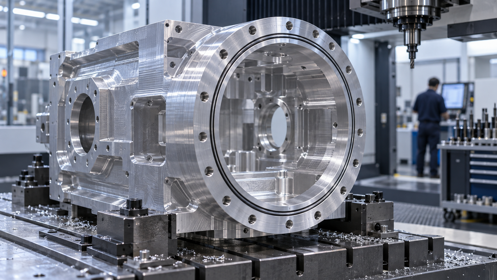
That drawing was passed to process engineer Lao Zhou on Tuesday afternoon. The part name read "Etch Chamber Upper Lid," material 6061-T6, overall size about 320×280×90 mm, with a stepped deep cavity inside, a ring of 24 M6 threaded holes on the flange face, and two seal grooves on the inner side. The requirements in the lower right corner of the drawing were not lenient: inner cavity surface Ra 0.4 μm, flange flatness 0.02 mm, unspecified dimensions according to general tolerances, but the seal groove width tolerance band was given as +0.02/0. The customer added a note: "The surface must not have scratches, burrs, or residual particles."
Lao Zhou did not rush to quote. He first put the drawing back where it belonged—in the wafer manufacturing process. Wafer preparation, pattern transfer, material doping, deposition, etching, and packaging: among these steps, etching and deposition are both completed in a closed chamber. The chamber is the container for the process: gas enters through the gas inlet, reacts on the wafer surface, and byproducts are pumped away. The inner surface shape, roughness, and sealing performance of the chamber directly determine whether the gas flow is uniform, whether the plasma is stable, and whether particles fall off. Therefore, the threshold for precision machining of semiconductor chambers is not "whether it can be milled out," but whether after machining it can still serve as a qualified process environment.
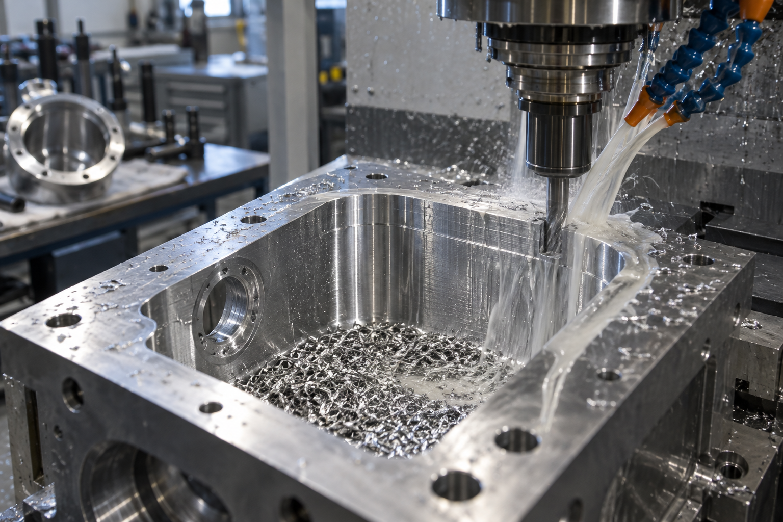
This brings four unavoidable difficulties. Thin walls deform easily—to reduce weight and conduct heat, chamber side walls are often only 5–8 mm. During rough machining, clamping and unclamping releases stress, and the flange face warps. Deep cavities are difficult for chip evacuation—the inner cavity depth is several times the tool diameter, chips cannot be discharged, and once the tool stops, it crowds the tool and causes edge chipping. Sealing surfaces have high requirements—once the seal groove and flange face have tool marks or flatness out of tolerance, the vacuum leak rate after assembly cannot be kept under control. Cleanliness cannot be fixed afterward—once particles are embedded in the surface, later cleaning is very difficult to remove them thoroughly.
What Equipment Is Needed for Precision Chamber Machining: An Equipment List from 5-Axis to Slow Wire Cutting
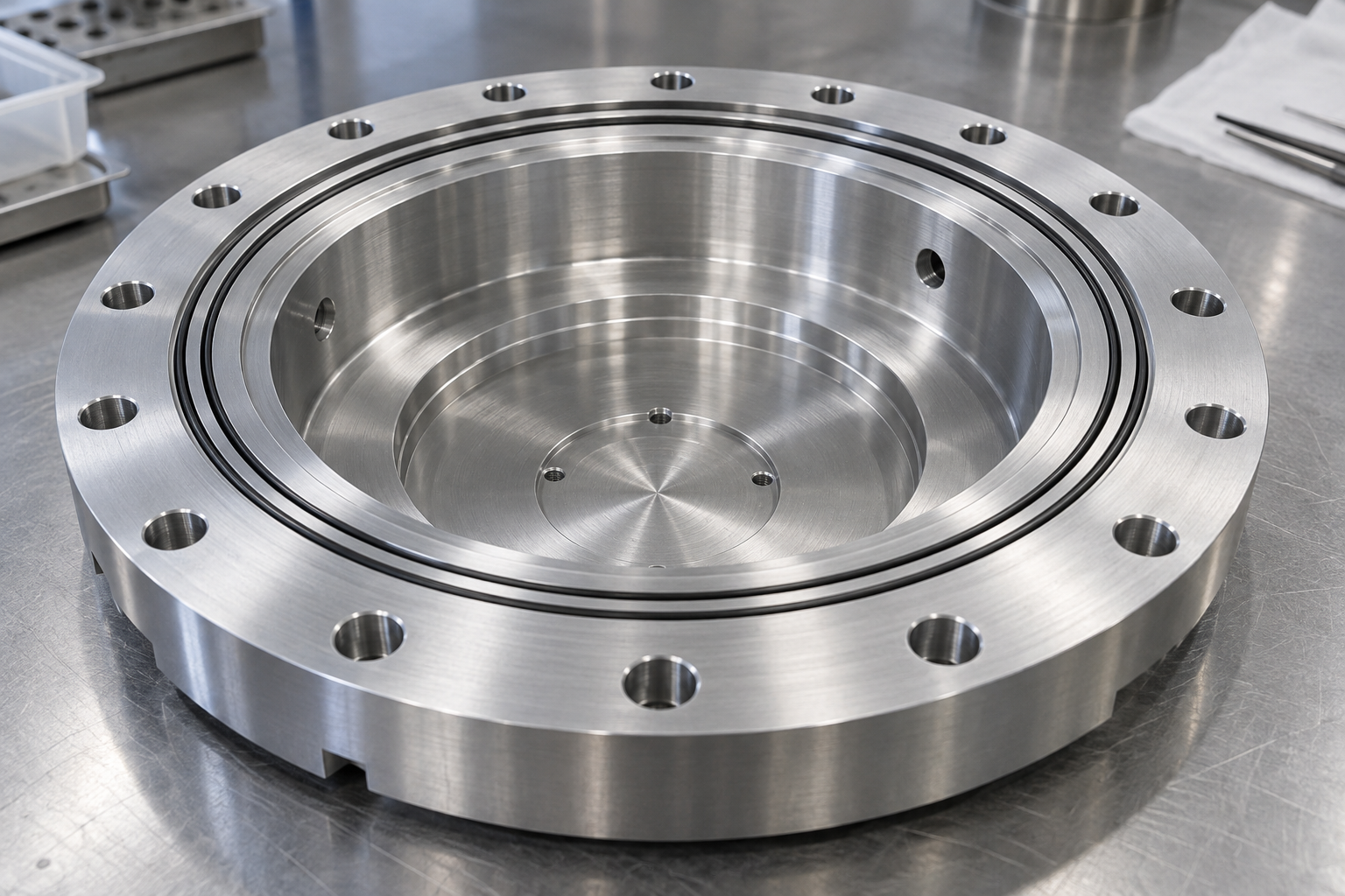
That afternoon, process engineer Lao Zhou spread the drawing on the workshop's stainless steel workbench. This was the lower body of an etch chamber, material 6061-T6 aluminum alloy, outer profile 420 × 380 × 260 mm, the inner cavity had to be dug to 180 mm deep, and the wall also had two rings of φ6 cooling water channels and six angled gas inlet holes. He pointed to the small text on the flange face and said: "For this ring of sealing surface, flatness has to be calculated in microns; for those corners in the inner cavity, the R angle cannot be large, or the gas flow will accumulate." Whether a chamber drawing can be realized often does not depend on whether there is a 5-axis machine tool, but on whether each type of equipment has been placed in the correct position.
The equipment used in precision machining of semiconductor chambers can be roughly divided by function into four groups: forming machining, special machining, joining and surface treatment, and inspection and cleanliness. Below, following the sequence of Lao Zhou's chamber from blank to shipment, each item is explained in terms of what problem it solves and the common precision magnitudes in the industry—note that these are judgment references, not delivery indicators we can promise.
Forming Machining Equipment: 5-Axis Machining Centers and CNC Lathes
- 5-axis machining centers: The multiple flange faces, angled gas inlet holes, and inner cavity steps on a chamber are often not on the same datum plane. The value of 5-axis is completing multi-face machining in one setup, reducing cumulative errors caused by repeated alignment. Common positioning accuracy in the industry is on the order of ±5 μm to ±20 μm. The tolerance band that can actually be stably controlled is also affected by tools, fixturing rigidity, and cutting heat. The specific value depends on where the key dimensions on the drawing are set.
- CNC lathes: The chamber's rotary end cover, viewing window flange, and seal ring grooves are rotary features. Turning makes it easier than milling to ensure roundness and end face perpendicularity. Thin-walled rotary parts require sequential turning and control of clamping force. In the industry, soft jaws or expanding sleeves are often used to reduce clamping deformation.
Special Machining Equipment: EDM and Slow Wire Cutting
- EDM die-sinking machines: For narrow slots deep inside the inner cavity, corner cleaning, and blind hole bottoms, milling cutters cannot reach or lack rigidity. Electrodes can be made into the corresponding shape, achieving R angles on the order of 0.2–0.5 mm, depending on electrode wear and discharge parameters.
- Slow wire EDM: Suitable for through irregular contours, thin-wall windows, and precision guide slots. The cut surface roughness is usually more uniform than milling, but efficiency is low, so it is mostly used for final contour cleaning.
Joining and Inspection Equipment: Vacuum Welding, CMM, and Clean Cleaning
- Vacuum welding equipment: Large chambers are often made by welding upper and lower halves together. Vacuum brazing or electron beam welding can reduce oxidation and deformation, but groove design and welding sequence directly affect the flatness of the subsequent flange face.
- Coordinate measuring machines and roughness testers: Dimensional tolerances, flange flatness, and inner cavity surface roughness are verified item by item with these. After finish machining, Ra is commonly on the order of 0.2–0.8 μm, and ultra-precision machining can be lower. The key depends on functional requirements.
- Clean cleaning lines: For particle residue control before chamber shipment, the industry has a reference value for single-wafer cleaning of attached particle count controlled below 10 particles/W (≥0.08 μm particles), and a reference value for batch cleaning of about 200 particles/W. The specific acceptance standard is subject to the drawing and customer specification.
Having listed the equipment to this point, Lao Zhou closed the drawing and said something practical: "Having all the equipment is only the admission ticket. What really determines whether this batch of chambers passes inspection is how each piece of equipment hands off to the next." The next section breaks down this series of handoffs in order from CAD to QMS.
The Process Chain for Chamber Machining: Eight Steps from CAD to QMS
When the aluminum alloy chamber drawing was spread in front of the process engineer, the first thing he did was not start the machine tool, but disassemble and reassemble the model in CAD. A chamber is not a single part, but a relay of a series of operations: if any link is loose, the later finish machining, welding, and cleaning cannot make up for it. The process chain below is divided into eight steps according to the order we actually followed during order tracking. Each step marks the point that precision machining of semiconductor chambers must watch in that operation.
Steps One to Three: Modeling Review, Process Planning, and Rough Machining to Remove Stock
1) Design modeling and manufacturability review. Convert the customer drawing into a machinable 3D model, focusing on tool accessibility in deep cavities, the positional relationship between flange bolt holes and seal grooves, and whether there are reinforcing ribs at thin walls. If this step is skipped, it is often only during finish machining that the tool is found unable to reach inside.
2) Process planning and cutting simulation. Determine the fixturing plan, datum planes, and tool paths, then run simulation in CAM. Industry experience is that simulation can reduce trial cutting time by about 40%—what is saved is not one cut, but the scrap risk of an entire block of aluminum material. In simulation, the tool deflection in deep cavities can be seen clearly, and the risk of chatter marks on thin walls can also be discovered in advance.
3) Rough machining to remove stock. Hollow out the blank with large cutting volumes, leaving allowance for semi-finish and finish machining. What this cut buys is not dimensions, but stress relief space for subsequent operations—if the internal stress of an aluminum alloy chamber is not released after rough machining, the flatness after finish machining will slowly drift away after a few days.
Steps Four to Six: Semi-Finish Machining, Finish Machining, and Special Machining for Corner Cleaning
4) Semi-finish machining and stress relief. Narrow the allowance to a level that finish machining can stably control, and arrange a stress relief operation in between—vibratory stress relief or heat treatment depending on material and structure. A common industry practice is to stop overnight after semi-finishing thin-walled chambers before finish machining, giving the dimensions a stable window.
5) Finish machining to preserve surface form. This is the decisive step for the surface quality of a precision chamber. After finish machining, surface roughness typically reaches Ra 0.2–0.8 μm in the industry, and ultra-precision machining can be lower, depending on the tool, spindle speed, and cooling method. The flatness of the flange sealing surface must be considered together with roughness—if roughness is good but flatness is poor, the seal ring still will not press tightly.
6) Special machining for corner cleaning and slot cutting. Deep narrow slots, internal right angles, and irregular contours that milling cutters cannot reach are handed to EDM die-sinking machines or slow wire EDM. What this step determines is the uniformity of the gas flow or chemical liquid channels inside the chamber, not an appearance part.
Steps Seven and Eight: Welding and Assembly, Surface Treatment, and QMS Inspection Archiving
7) Welding, assembly, and surface treatment. For split chambers, whether to weld first and then finish machine or finish machine first and then weld depends on the amount of thermal deformation. After welding, electrolytic polishing or polishing is required. Wet process chambers often also involve SS316 electrolytic polishing or PFA/PTFE liner assembly. Surface treatment is not decoration; it is a prerequisite for corrosion resistance and outgassing control.
8) Inspection and QMS archiving. Coordinate measuring machines verify dimensions and flatness, roughness testers verify the surface, vacuum leak detection verifies leak rate, and clean cleaning lines control particle residue. The data from each step goes into QMS, forming a traceable machining record. This chain from CAD to QMS is the real workload of semiconductor chamber machining—the three words turning, milling, and drilling cannot sum it up.
Materials and surface treatment: different requirements for chambers in wet and dry processes
The drawing says AL6061-T6, with hard anodizing on the flange face. But procurement first asked: is this chamber for wet or dry processing? That one question pulled material selection and surface treatment back from the "notes" to the front end of design. The chamber is the physical space where processes such as etching, deposition, and cleaning take place, and different process routes change the requirements for chamber materials as well.
Wet process chambers: corrosion resistance and liners first
Wet processes use acids, bases, and solvents to complete cleaning or etching inside the chamber, and the chamber is in long-term contact with chemical media. A common industry practice is to use a corrosion-resistant stainless steel such as SS316 for the main body, with electropolishing on the inner surface to reduce roughness and minimize chemical residue clinging to the walls; parts exposed to strongly corrosive media may be lined with PFA or PTFE. If aluminum alloy is used in a wet process chamber, it usually requires thicker anodizing or coating, and it must be confirmed whether the corrosion resistance rating covers the chemicals used—this point cannot be judged by material grade alone, and the chemical compatibility table must be checked item by item.
Dry process chambers: outgassing and particles are the main conflict
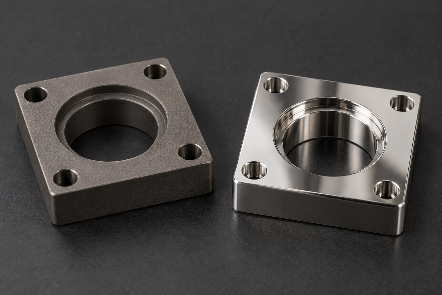
Chambers for dry etching, PECVD, and similar processes follow a vacuum route, with more attention to outgassing rate and particles. Aluminum alloy, titanium alloy, and ceramics are all options: aluminum alloy has good machinability and fast heat conduction, making it suitable for the chamber body; titanium alloy has high strength and corrosion resistance, and is often used for components exposed to plasma; ceramics have good insulation and are mostly used near dielectric windows or insulating rings. For surface treatment, aluminum alloy is often hard anodized or nickel-coated to improve wear resistance and resistance to plasma bombardment. It is worth noting that the anodized layer itself may adsorb moisture, and vacuum chambers usually need baking and degassing before assembly; the specific baking temperature and time must be verified according to the vacuum level requirements.
Surface treatment is not decoration. On the same drawing, reducing the inner surface Ra from 0.8 μm to the 0.2 μm level will noticeably change the tendency for particle adhesion and chemical residue—but whether this improvement is necessary should be judged together with the process cleanliness level; smoother is not always better. If it is only a structural support part, excessively pursuing a mirror finish instead increases cost and lead-time risk. For a chamber's materials and surface treatment, the ultimate questions to answer are: what process medium will it contain, what cleanliness level is required, and how long a maintenance cycle is acceptable.
Cleanliness and inspection: the final gatekeeper of chamber machining
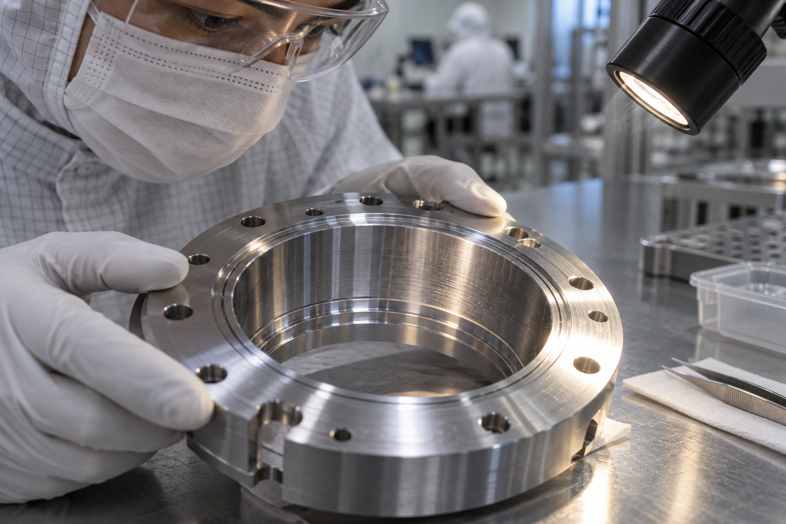
By the sixth week of order tracking, that aluminum alloy etching chamber finally came out of the clean cleaning line. Before assembly, the inspector, wearing gloves, turned over the flange face and looked for hanging fibers and residue under the oblique light of a strong lamp. He once told me: The place where chamber machining most easily goes wrong is often not the dimensions, but a particle invisible to the naked eye. A metal chip left on the chamber inner wall can scratch a wafer once it enters the equipment, or become a nucleation point for the next deposition—and the yield of the entire batch of wafers is gone just like that.
The reason precision machining of semiconductor chambers puts cleanliness and inspection as the final step is that the chamber is the physical space where the process takes place. In wafer manufacturing, etching, deposition, and cleaning are all completed in the chamber, and a common industry-wide full manufacturing cycle may be as long as 16–18 weeks, with packaging and testing still to be scheduled afterward. If any process step is scrapped due to chamber contamination, the previous dozen-plus weeks are all lost. This is also why chambers must be verified item by item before shipment, rather than relying on sampling.
Inspection items checked one by one: from dimensions to particle residue
- Dimensions and geometric tolerances: deep cavity depth, flange flatness, sealing surface parallelism. In the industry, precision machining commonly achieves the ±0.002–0.02 mm level, depending on equipment and process; sealing surface flatness is often tightened separately, because if the O-ring is not compressed firmly, it will leak.
- Surface roughness: after finishing, Ra is commonly at the 0.2–0.8 μm level; when the inner surface requires finer finish, superfinishing or electropolishing is needed. Roughness is directly related to particle adhesion and outgassing.
- Particle residue: after clean cleaning, verify by particle counting or wipe sampling. For single-wafer cleaning equipment, the number of adhered particles can be controlled in the industry to below 10 per wafer (particles above 0.08 μm), while for batch systems the reference is about 200 per wafer—the numerical difference shows that the cleaning method itself determines the cleanliness ceiling.
- Vacuum leak rate: helium leak testing is performed on every weld seam and every sealing surface. For chambers made by welding separate parts together, weld seams are high-risk leak areas.
- Dew point and environment: test environments such as probe stations require a dew point below -40°C; humidity tolerance in lithography areas may be strictly controlled within ±1% in the industry. Drying and packaging before chamber delivery must match this level.
This table is not finished after a one-time checkoff. Dimensions and geometric tolerances are reported on a coordinate measuring machine, a roughness tester supplements the inner surface data, and particles and leak rate are recorded by the cleanliness and leak testing stations respectively, finally filed into the QMS. If any item fails, it must return to the corresponding process—flatness out of tolerance may go back to finishing, and excessive particles often go back to the cleaning line for another pass. This is also why I call cleanliness the "goalkeeper": no matter how well the previous five processes are done, if this gate is missed, the chamber is not qualified.
If your drawing has similar chamber parts, rather than waiting until just before shipment to discover problems, it is better to raise the key tolerances, surface treatment, and cleanliness requirements together at the quotation stage. AI chat quotation can directly accept drawings and requirements, letting the process team judge before work starts which processes need key control.
Common questions about precision machining of semiconductor chambers
The following questions are the ones asked most often during order tracking. The answers are developed according to the equipment, process chain, and inspection logic mentioned in this article; for specific values, please refer to the drawing and actual process verification.
Which part of precision machining of semiconductor chambers is the hardest to control?
In most cases it is not a particular cut, but the deformation of thin-walled parts and the stability of the sealing surface. Chambers often have thin walls, deep cavities, and large flange faces, and residual stress after rough machining is released during finishing or welding, causing flatness to exceed tolerance. A common industry practice is to arrange a stress relief process after semi-finishing, then finish machine to maintain the surface form. For your specific part, you need to first look at wall thickness and flange span, then decide the clamping and stress relief rhythm.
What is the difference in machining requirements between wet process chambers and dry etch chambers?
Wet process chambers contact acid and alkali chemicals, so materials and surface treatment lean more toward corrosion resistance, and common industry choices include SS316 electropolishing and PFA/PTFE liners; dry etch chambers pay more attention to outgassing rate, particles, and vacuum sealing, with stricter control of surface roughness and cleanliness. The two differ in matching tooling, cutting fluid, and cleaning processes. Drawings usually mark the medium and cleanliness level, so follow the markings.
After chamber machining is completed, how is cleanliness verified?
Generally it is divided into several steps: dimensions and geometric tolerances are verified with a coordinate measuring machine, surface roughness is sampled with a roughness tester, particle residue is counted after clean cleaning according to the agreed particle size threshold, and vacuum chambers also require leak rate testing. In the industry, the number of adhered particles for single-wafer cleaning may be controlled below 10 per wafer (particles above 0.08 μm), but this is a reference for equipment capability, not something every chamber must achieve. For acceptance criteria, please rely on the drawing and the inspection items agreed by both parties.
How tight should the tolerances on a chamber drawing be?
In the precision machining industry, the typical achievable level is ±0.002 mm to ±0.02 mm, depending on equipment, material, and structure, and the repeatability of a closed-loop system is about the ±2–5 micron level. But tolerances are not better the tighter they are; sealing surfaces and mating surfaces should be tight, while non-mating surfaces can be relaxed to save cost. It is recommended to distinguish critical dimensions from general dimensions on the drawing so that process planning has room for trade-offs.
What should be noted in the process for small-batch chamber prototyping?
Small batches usually follow CNC machining or prototype duplication routes. First conduct a manufacturability review to confirm the feasibility of deep cavity chip evacuation, thin-wall clamping, and special process corner cleaning, then arrange the process chain. At the prototyping stage, it is recommended to include inspection items and cleanliness requirements in the technical agreement to avoid a situation where samples pass but mass production acceptance criteria are inconsistent. Lead time and price need to be evaluated according to the specific drawing, and no commitment is made here.
Key takeaways
- The chamber is the physical space where processes such as etching, deposition, and cleaning take place. Its machining accuracy, inner surface condition, and cleanliness are directly related to process uniformity.
- Precision chamber machining cannot be summed up in the three words turning, milling, and drilling. It is a chain: design modeling -> process planning and simulation -> rough machining -> finish machining -> special machining -> welding and assembly -> surface treatment and cleaning -> inspection and cleanliness verification.
- Commonly used equipment includes 5-axis machining centers, CNC lathes, EDM die-sinking machines, slow wire EDM, vacuum welding equipment, coordinate measuring machines, roughness testers, and clean cleaning lines. Each type of equipment corresponds to a specific difficulty in the chamber.
- Materials and surface treatment must match the process: wet process chambers often involve corrosion-resistant materials and liners, while dry etch chambers are more sensitive to cleanliness and outgassing control.
- Inspection and cleanliness control are the final gatekeepers. Dimensional tolerances, surface roughness, particle residue, and leak rate must be verified item by item; you cannot rely only on a final inspection report.



