Why Precision CNC Machining Cannot Be Specified Only as “High Precision”: The Relationship Between Tolerances, Materials, and Inspection
A drawing may state “precision machining,” yet provide no clear hole-and-shaft relationship or measurement datum for two holes; the material may be specified only as “aluminum alloy,” while the inspection requirement is simply “100% inspection.” Faced with a manufacturing project described this way, a supplier cannot accurately determine the machining process or confirm the boundaries for quotation and acceptance. Even after the part is produced, the two parties may interpret “qualified” differently.
Precision is not a complete procurement requirement. It must be translated into functional features, allowable deviations, material condition, machining methods, and an inspection plan. Tighter tolerances typically require more stringent fixturing, tool management, dimensional stabilization, and measurement resources, but they do not necessarily make the part better. Excessive specifications without functional justification may increase machining and inspection burdens without improving assembly or operating performance.
Define Precision Machining Tolerances Starting from Function
The engineering team should first explain how the part will function: which holes are used for positioning, which holes are for bearing or pin fits, which surfaces serve as mounting datums, and which dimensions are only for clearance or the external profile. The positional relationship of locating holes, the diameter and geometric tolerances of bearing bores, and the flatness or perpendicularity of mounting surfaces are often more deserving of individual control than nonfunctional external profiles. Dimensional conformity does not necessarily mean that assembly will be successful; hole position, coaxiality, datum translation, and surface roughness may jointly determine the result.
Include Material Condition and Inspection Requirements in Precision Manufacturing Documents
Descriptions such as “aluminum alloy,” “steel,” or “engineering plastic” are generally insufficient for a precision CNC machining review. Material grade, supply condition, heat treatment, and surface treatment affect cutting loads, tool wear, thin-wall distortion, thermal expansion, and subsequent dimensional changes. It must also be made clear whether critical dimensions are to be accepted before or after surface treatment. At the same time, four questions should be answered in advance for every critical feature: What datum will be used for measurement, what feature will be measured, what gauge or equipment will be used, and what record will be provided? Only when functional requirements, tolerances, materials, and inspection form a reproducible chain can the supplier develop a reasonable process and the project establish consistent acceptance criteria.
ISO 2768 and ISO 286 in Precision CNC Machining: How to Distinguish General Dimensions from Hole-and-Shaft Fits
In precision CNC machining drawings, the most likely source of misunderstanding is not the name of the standard but its scope of application. ISO 2768 is primarily used for linear and angular dimensions that are not individually specified on the drawing; ISO 286 is more commonly used for fits involving holes, shafts, and two parallel opposing surfaces. Both may be used separately on the same part, but general tolerances do not automatically cover critical fits, geometric tolerances, or functional datums.
General Dimensions in Precision Manufacturing: ISO 2768 Is Not a Fixed ±0.1 mm Table
ISO 2768 tolerance classes are generally related to nominal size ranges. Within the same class, shorter and longer dimensions may not use the same permissible deviations. Using the illustrative examples in the source table, ISO 2768-m gives different example values for the 3–6 mm and 30–120 mm linear dimension ranges. This shows that in precision machining, having “ISO 2768-m” in the title block does not mean that all dimensions are allowed the same deviation. For formal projects, the applicable standard version, drawing general notes, and specific callouts should still be verified.
Hole-and-shaft fits and critical datums: ISO 286 cannot replace functional definition
Bearing bores, pin holes, locating holes, and shaft fitting surfaces require their functions to be defined first, followed by selection of the appropriate hole-and-shaft tolerance zones. IT6, IT7, and IT8 in ISO 286 represent different tolerance grades; the source examples show that the corresponding values are not the same in the 3–6 mm size range. This difference can only be used to understand the relationship between grades and must not be applied directly without considering the hole-and-shaft fit, material, assembly clearance, and operating temperature.
| Feature type | Suitable definition method | Details that must not be omitted |
|---|---|---|
| Non-functional external profiles and general installation dimensions | Applicable general tolerance | Nominal size range, angle, and standard version |
| Holes, shafts, and bearing seats | Hole-and-shaft tolerance zone or independent dimensional tolerance | Fit relationship, datums, surface roughness, and acceptance condition |
| Locating holes and hole patterns | Basic dimensions plus positional or related geometric tolerances | Datum system, hole-position relationship, and measurement method |
| Mounting datum surfaces and sealing surfaces | Independent requirements for flatness, perpendicularity, parallelism, or surface roughness | Functional direction and condition before and after surface treatment |
Dimensional tolerances, geometric tolerances, and surface roughness must also be distinguished. General tolerances cannot automatically replace requirements for flatness, perpendicularity, concentricity, or parallelism, nor can they automatically specify surface roughness. If a hole must fit a shaft, simply stating “precision machining” or referencing a general tolerance still does not tell the supplier how the hole diameter, hole position, and datum relationships should be accepted. Drawings and quotation documents should clearly specify critical features, datums, fit conditions, and inspection methods. Appropriate general tolerances can then be used for the remaining non-functional dimensions, avoiding the application of the strictest grade to every feature.
Which precision machining features must have individually specified tolerances: establishing a tiered definition using a mounting base
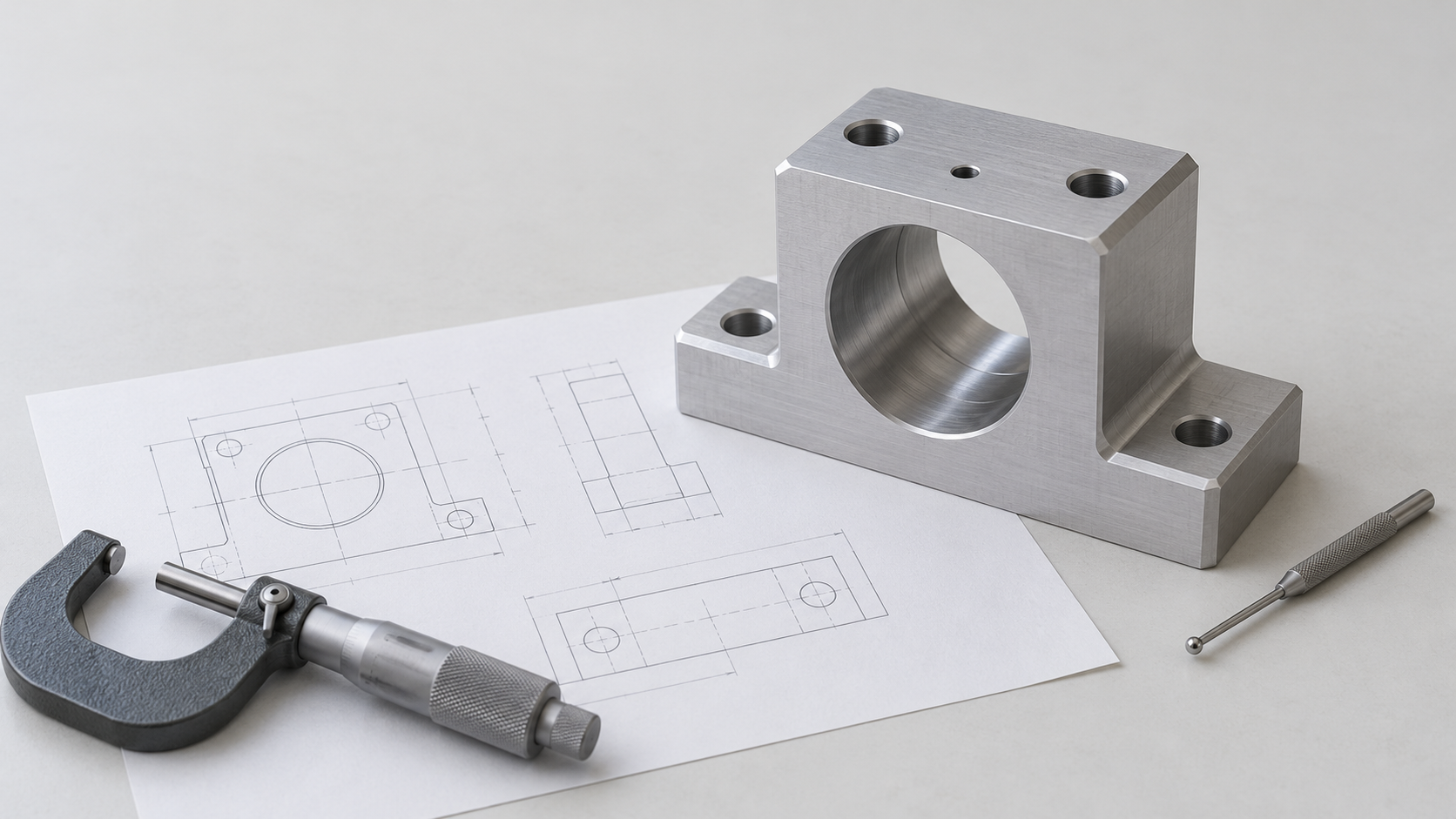
An aluminum alloy mounting bracket may contain locating holes, a bearing bore, mounting datum surfaces, and a non-functional outer profile at the same time. All of these are part of the same precision machining task, but they should not be assigned the same tolerance grade. The criterion is not “where it looks precise,” but whether the feature participates in positioning, assembly, load transfer, sealing, or motion. Functional features should be defined separately, while non-critical external profiles should use applicable general tolerances. This usually makes the machining and acceptance requirements easier to execute.
Precision machining: classify features by function first, then determine the dimensioning method
For the two locating holes, first clarify the hole diameter, hole locations, and the dimensional or positional requirements relative to the datum surfaces. Controlling only the hole diameter without controlling the hole location may result in “all holes passing inspection while the part still cannot be assembled.” For a bearing bore, it is not enough to specify only a diameter tolerance. The bearing fit, roundness, cylindricity, relationship between the bore axis and other datums, and bore-wall roughness must also be considered to determine whether the function is satisfied. If the bearing bore has coaxiality or relative-position requirements with another hole pattern, a clear datum system should be established on the drawing.
When a mounting datum surface is responsible for assembly positioning, flatness, perpendicularity, or parallelism should be considered based on the actual assembly chain. Dimensional compliance does not mean that the datum relationships are compliant: a surface may meet the dimensional requirement for flatness but cause the mounted component to tilt because its flatness is insufficient; likewise, the diameters of two holes may both be within tolerance, yet positional deviation may prevent the fastener from passing through.
| Feature | Primary function | Recommended dimensioning focus | Supplier to confirm |
|---|---|---|---|
| Locating hole | Define the assembly position | Hole diameter, hole location, positional requirements relative to the datum, and, where necessary, hole-axis direction | Datum establishment method, hole-location inspection method, and whether a complete first-article dimensional record is required |
| Bearing bore | Provide a rotating fit or support | Fit diameter, roundness, cylindricity, axis relationship, and roughness | Mating component and assembly condition, measurement datum, and format of the bore-diameter and geometric-tolerance report |
| Mounting datum surface | Provide positioning or support | Flatness, as well as perpendicularity and parallelism relative to the hole pattern or adjacent surfaces | Clamping datum, machining sequence, and acceptance condition before and after surface treatment |
| Non-functional outer profile | Satisfy the profile and clearance requirements | Applicable general linear and angular tolerances | Whether any unspecified interference, appearance, or assembly boundaries exist |
Convert critical features into information that suppliers can execute
The rule is: features involved in assembly and operation should be dimensioned separately, while profile dimensions should be controlled according to the applicable general tolerances. Exceptions include thin-wall areas, deep holes, heat-treated parts, and surface-treated parts; even when these features do not directly participate in mating, they may affect assembly due to deformation or dimensional changes after treatment. Drawings or RFQ documents provided to suppliers should at least specify the datum sequence, critical feature numbers, dimensional and geometric requirements, surface roughness, material condition, surface treatment, and final acceptance condition.
It should also be stated whether the inspection concerns an individual feature or the relationship between features. For example, “100% inspection of the two locating holes” is still insufficiently specific. It must be clarified whether the inspection covers hole diameter, hole position, hole axis, or the relative position between the two holes. This allows quotations, process reviews, and first-article inspections for precision machining to be based on the same set of functional requirements, rather than requiring the meaning of “precision” to be interpreted after machining is complete.
How Materials Change Precision CNC Machining Tolerances: Hardness, Thermal Stability, and Deformation Risk
In precision CNC machining, “aluminum alloy,” “steel,” or “plastic” is not a complete material requirement. The material grade, supplied condition, heat treatment, surface treatment, and final acceptance condition all affect the machining route, tolerance control, and measurement timing. The tighter the tolerance, the more apparent the effects of material behavior on fixturing, tooling, and dimensional stability become; a fixed result cannot be promised based solely on the general material category.
Aluminum Alloys in Precision CNC Machining: Thin Walls, Fixturing, and Thermal Expansion
Aluminum alloys generally offer good machinability, but thin walls, narrow edges, and locally unsupported areas can easily deform under clamping or cutting forces. Heat generated during machining, as well as the temperature difference between the part and its surroundings, can also cause dimensional readings to change. For mounting bases, housings, or brackets with thin-wall structures, the minimum wall thickness, critical surfaces, and fixturing limitations should be specified during the RFQ stage. Where necessary, the support method and machining sequence should also be discussed.
Although both may be described simply as “aluminum alloy,” different grades and conditions vary in strength, residual stress, and dimensional stability. Drawings or purchasing documents should at least specify the exact grade, supplied condition, and surface treatment requirements such as anodizing or painting. It should also be confirmed whether critical hole diameters, datum surfaces, and mating dimensions are to be accepted before or after surface treatment.
Steel, Stainless Steel, and Engineering Plastics in Precision CNC Machining
The hardness, work-hardening tendency, and abrasiveness of steel and stainless steel can increase cutting loads and tool wear. Changes in tool condition can cause dimensional drift, while the release of residual stress after heat treatment can also deform parts. Therefore, for heat-treated parts, the machining allowance, process sequence, and whether critical dimensions are to be inspected before heat treatment or in the final condition should be confirmed in advance. For high-hardness or wear-resistant materials, the supplier must also confirm the tooling, fixturing, and subsequent finishing arrangements.
For engineering plastics, particular attention should be paid to heat accumulation, clamping deformation, moisture absorption, and long-term dimensional stability. Measuring plastic parts immediately after machining may not represent their stable dimensions in the assembly environment. For bushings, sliders, and sealing-related parts, the operating temperature, mating function, and measurement condition should be specified rather than simply stating “precision plastic machining.”
| Material or Condition | Primary Machining Risks | Items to Confirm in the Purchasing Documents |
|---|---|---|
| Thin-Wall Aluminum Alloy Parts | Clamping deformation, cutting heat, and dimensional changes after surface treatment | Grade and condition, minimum wall thickness, and the acceptance stage for critical dimensions |
| Steel or Stainless Steel | Cutting load, tool wear, residual stress, and heat-treatment deformation | Hardness or heat-treatment requirements, machining allowance, and final inspection condition |
| Engineering plastics | Heat accumulation, moisture absorption, clamping deformation, and long-term dimensional changes | Grade, operating temperature, assembly function, and measurement conditions |
During the actual review, material information should correspond one-to-one with critical features: which hole requires a stable fit, which datum surface determines assembly, which thin-wall area may deform, and which dimensions must be remeasured after surface treatment. Only by defining precision manufacturing requirements in this way can the process review, quotation, and acceptance all be supported while avoiding a disconnect between material names and tolerance requirements.
From Rough Machining to Stabilization: How Precision Manufacturing Controls Dimensional Drift
Precision manufacturing cannot rely solely on the final finishing operation to “recover” dimensions. Tolerance requirements should be implemented throughout the process route: the blank condition, rough-machining allowance, semi-finishing, finishing, heat treatment or surface treatment, and final inspection condition must all be included in the same dimensional control chain. Tight tolerances usually require stricter control of fixturing, temperature, tooling, and inspection, but this does not mean that every feature should be assigned the most stringent tolerance grade.
Allowances, Fixturing, and Datums in Precision Manufacturing
The purpose of rough machining is to remove the main allowance while avoiding excessive deformation caused by cutting heat, the release of residual stress, or clamping force. For thin-wall, deep-cavity, and long overhang structures, an appropriate allowance usually needs to be retained after rough machining, followed by semi-finishing and finishing to gradually approach the target dimensions. The specific allowance cannot be defined independently of the material, part dimensions, and tool condition; it should be confirmed by the supplier in conjunction with the process review.
Multiple setups introduce datum-transfer errors. For locating holes, bearing bores, and interconnected hole patterns where a highly accurate positional relationship is functionally required, priority should be given to evaluating whether they can be completed within the same datum system, or to clearly defining how the datum will be reproduced during a secondary setup. During the supplier review, ask directly: Do the critical holes need to be completed in a single setup? How will the datum surfaces be established? How will thin-wall areas be supported? Which dimensions will be rechecked after re-fixturing?
Tool Wear, Cutting Heat, and Within-Batch Dimensional Drift
Tool wear gradually changes bore diameter, slot width, outside diameter, or surface condition; cutting heat may cause the workpiece to show different readings during machining and after cooling. Because material hardness, abrasiveness, and thermal stability vary, dimensional drift also manifests differently. Therefore, precision CNC machining should not only confirm “which machine tool is used,” but also how tool life is monitored, when compensation or tool changes are performed, and at what temperature and in what condition critical dimensions are measured.
For batch-produced parts, first-article acceptance and ongoing stability must be distinguished. The first article should verify the datum, critical dimensions, geometric relationships, and conditions before and after surface treatment; subsequent production should undergo in-process sampling or adjustments according to the process plan. If the drawing only states “100% inspection” without specifying the features, gauges, measurement conditions, and record format, the inspection results may still not be reproducible.
For heat-treated or surface-treated parts, the dimensional control checkpoints should be specified in advance. It is necessary to confirm whether allowance will be retained on critical surfaces before treatment, whether finish machining will be performed afterward, which areas require protection, and whether final acceptance will take place before or after treatment. Processes such as anodizing aluminum alloys and heat treating steel parts may change dimensions or surface condition, so post-treatment deviations cannot simply be attributed to CNC machining.
When requesting quotations from or reviewing suppliers, it is recommended to frame process confirmation as questions that can be answered: What is the machining datum for the critical features? How will thin-wall areas be fixtured? Is stabilization or sufficient cooling scheduled before finishing? How is tool wear recorded? How are first articles and batch-produced parts distinguished during inspection? In this way, the tolerance requirements for precision manufacturing can be transformed from drawing values into an executable and traceable production plan.
From Drawing to First-Article Inspection: Matching Gauges and CMMs to Precision Machining Features
Inspection requirements for precision machining should not be added only after the part is completed. During the drawing review and quotation stages, four questions should be answered for each feature: What datum will be used for measurement? What feature will be measured? What equipment will be used? What records will ultimately be provided? Otherwise, even if the dimensional results are close to the requirements, the supplier and purchaser may still dispute the results because of differences in datums, measurement conditions, or acceptance methods.
Precision Machining Gauges Must Match the Features and Tolerances
For simple profiles or dimensions with relatively generous tolerances, calipers may be considered when the workpiece is stable and the contact method is appropriate; dimensions of approximately 0.01–0.05 mm may require a micrometer or other dedicated gauge; requirements of approximately 0.005 mm or less generally require a CMM or another more suitable high-precision measurement solution. These ranges are only empirical guidelines, not universal selection rules. Workpiece size, feature depth, measurement uncertainty, ambient temperature, datum establishment method, and the company's inspection standards will all affect equipment selection.
| Inspection Items | Common Points of Attention | Inspection methods to consider | Information to confirm in the documents |
|---|---|---|---|
| General overall dimensions | Length, width, and thickness | Calipers, micrometers, or dedicated measuring instruments | Measurement locations, accuracy requirements, and sampling ratio |
| Bore and shaft diameters | Dimensions, roundness, and fit relationship | Inside-diameter gauges, micrometers, air gauges, or CMM | Hole and shaft datums, fit class, and measurement conditions |
| Hole locations and complex hole patterns | Position tolerance, coaxiality, and hole spacing | CMM or suitable dedicated inspection fixture | Datum system, evaluation method, and report format |
| Datum surfaces and geometric tolerances | Flatness, perpendicularity, and parallelism | CMM, platform-based measuring instruments, or dedicated inspection fixtures | Datum sequence, point-taking rules, and acceptance criteria |
What should be recorded during first-article inspection for precision manufacturing machining
CMM is suitable for first-article inspection, evaluating hole locations and geometric tolerances, and performing full-dimensional inspection of complex parts. However, the equipment capabilities stated on a particular supplier's page must not be treated directly as a guarantee for all equipment. A first-article inspection plan should include at least the material grade and batch information, critical dimensions, geometric tolerances, surface roughness, surface treatment status, measurement temperature, and workpiece condition. It should also specify which items require 100% inspection and which require sampling inspection, and whether the report will use a dimensional checklist, an inspection report, or a graphical record with measurement point locations.
For parts after heat treatment or surface treatment, it should be clearly specified whether final acceptance is performed before or after treatment. For hole locations, bearing bores, and mounting datums, the report should not list dimensions alone; it should also describe how the datums were established and the evaluation results. Nonconformance disposition should also be agreed upon in advance: rework, acceptance under concession, or reconfirmation of the functional requirements.
Minimum Information Package Before Submitting to a Precision Machining Supplier
It is recommended to submit the following with the RFQ documents: the latest 2D drawings and revision numbers, 3D models, material grades and supply conditions, heat treatment and surface treatment requirements, a list of critical features, the datum reference system, applicable general tolerances or fit standards, inspection equipment and reporting requirements, and sample or first article requirements. If certain dimensions are only for appearance or clearance, do not assign them the same tight tolerance level as bearing bores, locating holes, and sealing surfaces. The more specific the information, the easier it is to maintain consistency in the process review, quotation scope, and final acceptance of precision manufacturing and machining.
Frequently Asked Questions: How to Confirm Tolerances, Materials, and Inspection for Precision CNC Machining
Acceptance of precision CNC machining cannot be based solely on whether a single dimension is within specification. It must also be confirmed in conjunction with function, tolerances, material condition, datums, and measurement methods. The following questions should be clarified in advance during drawing reviews and supplier communications.
Can general tolerances replace tolerances for critical dimensions?
Usually not. General tolerances are suitable for non-critical dimensions that are not individually specified. Locating holes, bearing bores, sealing surfaces, mounting datums, and hole-and-shaft fits should have individually specified dimensional tolerances and, where necessary, geometric requirements based on their functions.
When should GD&T be used in precision manufacturing and machining drawings?
When assembly or operating performance depends on datum relationships such as hole locations, coaxiality, flatness, perpendicularity, or parallelism, the use of GD&T should be considered. The specific symbols, datum reference system, and tolerance values should be determined jointly based on the functional chain and inspection plan.
Is it sufficient to specify only “aluminum alloy” for the material?
Usually not. The specific grade, supply condition, heat treatment, and surface treatment should be confirmed, and it should be stated whether critical dimensions are to be accepted before or after treatment. Thin-wall deformation, thermal expansion, and residual stress can all affect precision machining results.
Must all dimensions be measured using a CMM?
Not necessarily. Measuring instruments should match the feature, tolerance zone, and measurement uncertainty. Simple dimensions may be suitable for calipers or micrometers; hole locations, complex geometric features, and full-dimensional first article inspection often warrant the use of a CMM. However, the final decision should be based on the measurement plan and the supplier’s inspection specifications.
What should be included at a minimum in first article inspection for precision CNC machining?
At a minimum, it should cover material and batch information, critical dimensions, geometric tolerances, surface treatment, roughness, measurement datums and conditions, and clearly define the inspection scope, equipment, report format, and method for handling nonconformities.
Key takeaways
- “Precision machining” cannot replace specific dimensional tolerances, geometric tolerances, datums, and acceptance methods.
- ISO 2768 is suitable for general linear and angular dimensions that are not individually specified. Hole-and-shaft fits and critical functional features should be defined separately.
- Material grade, supply condition, heat treatment, and surface treatment may affect machining stability and final dimensions and must be confirmed together with the tolerances.
- Inspection requirements should be determined during the quotation and drawing review stages, including measurement datums, gauges or CMM, measurement conditions, and report scope.
- Before submitting the project to a supplier, prepare the drawing revision number, 3D model, material information, critical feature list, datum system, and first-article requirements.



