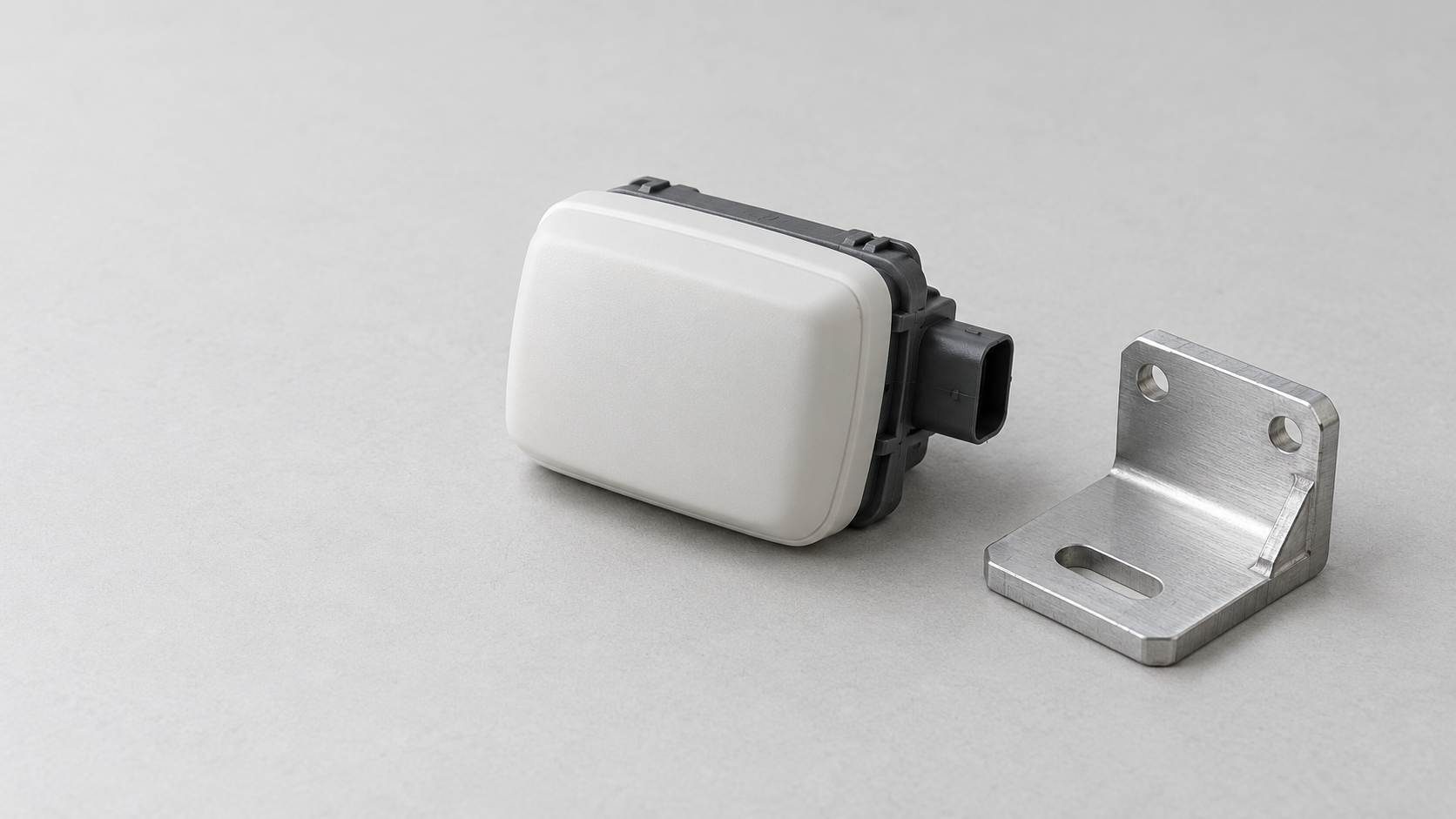
Why Do Autonomous Driving Sensor Housings and Mounting Brackets Affect Perception Accuracy?
Passing performance tests for the radar or camera itself does not mean that the autonomous driving sensor will continue to operate reliably after vehicle installation. Actual perception results must also pass through a mechanical chain: chip or antenna performance is ultimately transmitted through the radome, camera window, housing datums, and mounting bracket to the vehicle coordinate system, calibration parameters, and road-target data. A deviation at any point in this chain can turn a “qualified part” into an “assembly with inconsistent post-installation performance.”
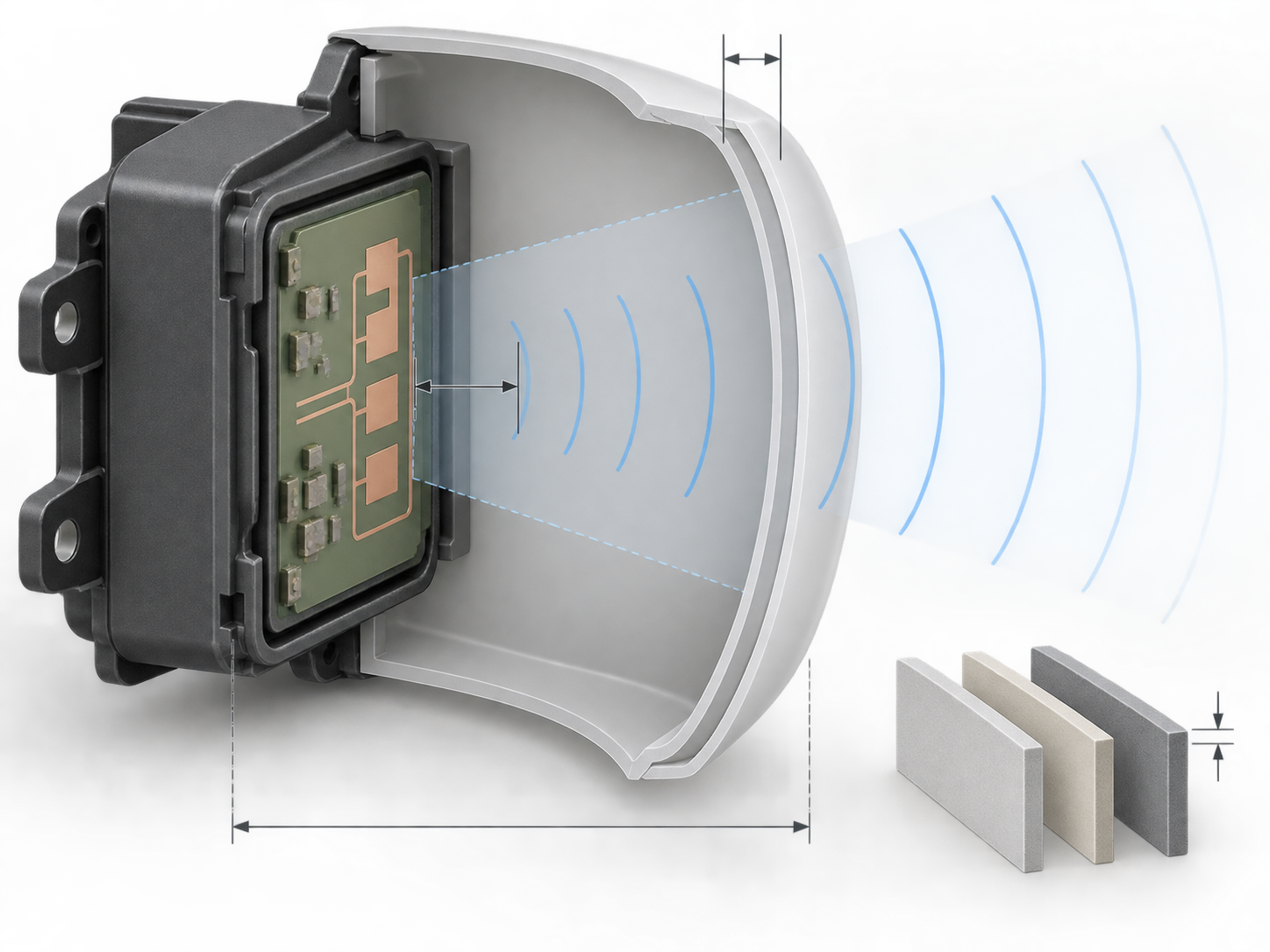
For millimeter-wave radar, the protective cover is not an ordinary protective component. The material’s relative permittivity and loss tangent, thickness uniformity in the beam region, curvature, and distance between the radar and protective cover can all change electromagnetic-wave propagation and reflection conditions. Brackets, ribs, or other structures near the protective cover may also cause blockage or stray reflections if they intrude into the beam region. Therefore, radar housings must be evaluated for electromagnetic characteristics, structural dimensions, and installation position at the same time, rather than being accepted solely based on appearance or material grade.
The impact path is different for cameras. Window light transmittance, whether the housing blocks the edge of the field of view, surface contamination, fogging, and window curvature all affect image quality. The mounting bracket determines the sensor’s yaw, pitch, and roll attitude; being able to assemble the holes does not mean that the optical axis or radar coordinate system meets the requirements. Vehicle mounting-surface tolerances, bracket machining errors, fastening deformation, and displacement after vibration also accumulate in the final attitude.
Therefore, the development of autonomous driving sensor housings and mounting brackets should begin with “what mechanical boundaries are required for perception performance” and then be translated into measurable datum surfaces, hole locations, clearances, angles, curvatures, and sealing interfaces. In engineering, certain common layout schemes may specify the radar ground clearance, protective-cover spacing, or camera attitude range, but these figures apply only to specific vehicle models, sensors, and coordinate systems and cannot be treated as universal standards. After part dimensional inspection is completed, verification must also incorporate assembly attitude, calibration, and target-object data to demonstrate that the manufacturing result truly meets the operating requirements of the autonomous driving sensor.
How Should Materials and Design Thickness Be Selected for Millimeter-Wave Radar Radomes?
The radar radome of an autonomous driving sensor is not an ordinary protective cover. Millimeter waves must pass through the radome to reach the target, and the material’s relative permittivity (Dk), loss tangent (Df), water absorption, temperature stability, and thickness uniformity can all affect electromagnetic-wave attenuation and beam shape. Frequencies around 24 GHz and 76/77 GHz are common operating bands for millimeter-wave radar, but the material grade or radome thickness cannot be determined solely from the frequency band.
Materials Selection for Autonomous Driving Sensors Must Return to Structure and Testing
In engineering, material families such as PPE, PC, PBT, and PPS can be included in the initial selection, but the material name is only a starting point. Supplier data usually needs to be re-evaluated within the actual structure: the electrical properties and dimensional stability of the same resin may differ under different thicknesses, curvatures, temperatures, and damp-heat conditions. Injection-molded parts also require attention to shrinkage, warpage, weld lines, and batch-to-batch variation. Therefore, material selection should be based on the target frequency band, beam-region thickness, weather-resistance requirements, and electrical performance testing of sample parts, rather than treating a particular grade as a universal answer.
Radar Radome Thickness, Curvature, and Spacing Require Integrated Verification
Radome design should generally avoid noticeable thickness changes, local abrupt transitions, or coating buildup in the beam region, and electromagnetic performance should be confirmed through surface-profile simulation and prototype testing. A reference example for a forward-facing millimeter-wave radar layout specifies a protective cover curvature radius greater than 600 mm, a distance between the radar and protective cover of approximately greater than 15 mm and less than 40 mm, and a clearance of more than 5 mm between the beam and surrounding structures. These values apply only to a specific sensor, coordinate system, and structural design, and must not be treated as universal specifications for all autonomous-driving sensor housings. The final values should be jointly determined by the sensor manufacturer, vehicle coordinate system, and product validation plan, and remeasured in the installed vehicle condition.
How should the camera window, sensor housing, and mounting bracket be zoned?
An autonomous-driving sensor housing is more than a protective cover. The camera window, radar radome, main housing, and mounting bracket each occupy different optical, electromagnetic, thermal, and mechanical boundaries. During design, the functions should first be divided into zones, followed by determination of the materials, datums, and assembly method. Even if a part has an acceptable appearance and its holes can be assembled, this does not mean that the field of view, beam direction, and orientation will still meet requirements after the sensor is installed in the vehicle.
Functional boundaries of the camera window and radar radome
The camera window must first ensure light transmission and field of view. The frame, reinforcing ribs, or assembly eccentricity must not intrude into the effective imaging area. Dust, mud and water, scratches, fogging, and subsequent cleaning must also be considered. Changes in window curvature and thickness may affect imaging, so acceptance cannot be based solely on the exterior contour. For a radar radome, attention must be paid to the material's electrical properties in the beam region, thickness uniformity, curvature, and relative position to the antenna. Coatings, decorative layers, or local wall-thickness changes should be verified during the prototype stage in conjunction with the operating frequency band and measured data.
Controlling datums and orientation for autonomous-driving sensor mounting brackets
The main housing must simultaneously provide connection, heat dissipation, thermal cycling, and sealing-interface functions. The bracket should establish clear locating surfaces, mounting holes, and rotation datums, while also evaluating body-tolerance stack-up, vibration, and deformation under load. In one reference design, a front-view camera mounting height of over 1200 mm was used as an example, with an orientation close to zero degrees. Another design specified an orientation range of approximately ±3°, a positioning tolerance of ±1 mm, and a rotational tolerance of ±2.5°. These figures can serve only as references for a specific layout and must not be treated as universal standards for all vehicle models. Engineering drawings should convert height, yaw, pitch, roll, and hole locations into measurable dimensions, which should be rechecked after assembly using an angle gauge or dedicated inspection fixture.
What manufacturing processes are used for autonomous-driving sensor housings and brackets?
The process selection for autonomous-driving sensor housings and mounting brackets depends on the part's function, development stage, production volume, and validation objectives. Housings must balance curved surfaces, sealing, and window or radome performance, while brackets place greater emphasis on datum surfaces, hole locations, orientation retention, and assembly deformation. The process should not be selected solely according to the apparent complexity of the part.
Plastic injection molding for housings; CNC machining for bracket prototypes
Injection molding is suitable for complex curved surfaces, snap-fits, reinforcing ribs, and high-volume plastic housings. During design, however, shrinkage, warpage, weld lines, gate marks, and the effects of material-batch variation on dimensions and electrical performance must be evaluated. Abrupt thickness changes should be avoided in critical areas of radomes or camera windows, and parting lines, ejector marks, and subsequent sealing interfaces should be included in appearance and functional inspections.
CNC machining is suitable for metal or plastic prototypes, low-volume brackets, and structures requiring rapid modification. Before programming, the workholding datums, locating surfaces, and tool accessibility should be clearly defined. Thin-walled brackets, deep cavities, or overhanging structures may deform due to cutting forces and reclamping, so hole locations and orientation should be remeasured using a common datum system.
Applicability boundaries of sheet metal, 3D printing, and plastic welding
Sheet-metal stamping, bending, and welding are suitable for metal mounting brackets and supports, but springback, hole-position drift, welding deformation, and surface-treatment thickness must be controlled. 3D printing can quickly verify exterior form, assembly clearances, and the camera field of view, making it suitable for prototype iteration. If a prototype must withstand long-term vibration, thermal cycling, or sealing functions, its material, surface quality, and environmental limits must be reconfirmed.
Plastic laser welding generally uses a transmissive layer and an absorptive layer, allowing laser energy to be converted into heat at the interface and form a continuous fusion joint. It may reduce the need for adhesives and some fasteners, but weld width, clamping pressure, part warpage, and the process energy window must still be controlled. Ultrasonic welding is limited by joint structure and vibration transmission. Hot-plate welding requires consideration of melting, cooling, and flash, while adhesive bonding requires management of bead continuity, curing conditions, and material compatibility. A sealing ring combined with mechanical fastening facilitates disassembly, but requires stable control of the sealing groove, compression interface, and fastening sequence. The final choice should be based on the housing structure, production volume, and validation plan, rather than treating any single process as universally optimal.
How can sensor housings achieve dustproof and waterproof sealing?
Sealing an autonomous-driving sensor housing is not a matter of applying a bead of adhesive after assembly. It must be defined from the housing parting line, sealing groove, compression interface, and connector cable exit. If warpage, eccentricity, or local gaps exist between the radome, camera window, and rear housing, the sealing ring may be unable to form continuous contact. Parting-line mismatch and inconsistent screw-tightening sequences may also create excessive local stress and leakage paths.
First define the sealing interface of the sensor housing
When a sealing ring is used, the drawing or process documentation should clearly specify the sealing-groove location, mating surfaces, material compatibility, and assembly direction, while controlling shrinkage and warpage of the plastic parts. Adhesive bonding is suitable for forming a continuous bead, but broken beads, bubbles, contamination, and insufficient curing must be avoided. Welding depends on weld width, compression condition, energy or temperature conditions, and the clamping and positioning of the upper and lower housings. Connector cable exits, vent membranes, and drainage paths are also part of the sealing system. Stress at a cable exit may pull the interface open, while a completely sealed cavity may develop a pressure differential due to temperature changes. These issues therefore require a design that combines venting with protection against liquid ingress.
Sealing processes must correspond to traceable validation
During assembly, the cleaning, adhesive-dispensing or welding parameters, compression time, tightening sequence, and appearance acceptance criteria should be specified. After sealing is completed, it is not sufficient to check only whether the housing is closed, nor can a single ingress-protection rating label replace verification. The retest items after airtightness, watertightness, rain spray, temperature-and-humidity cycling, salt spray, and vibration testing should be determined according to the product specification and verification plan. For small-batch prototypes, at minimum, the test conditions, prototype status, and leakage determination results should be recorded. If the sensor housing deforms after environmental testing, the assembly datums of the window, radome, and bracket should also be rechecked to confirm that changes in sealing have not further affected the sensing region.
How can the accuracy of the sensor housing, mounting bracket, and assembly be verified?
Acceptance of autonomous-driving sensor components cannot be based solely on whether the housing is scratched or whether the holes in the bracket can be used for installation. A more reliable sequence is to confirm the machining datums, complete the sealing assembly, inspect dimensions and orientation, conduct environmental and vibration verification, and finally confirm the sensor output through power-on, calibration, and target-object data. Only in this way can “part acceptance” be connected with “perception-function acceptance after vehicle installation.”
First check the datums, hole locations, and critical contours
For sensor housings and mounting brackets, a CMM or vision measurement system can be used to inspect datum surfaces, mounting-hole locations, locating-pin holes, window contours, and critical clearances. For radar radomes, the thickness, curvature, and appearance of the effective area should also be checked. For camera windows, the transparent area should be inspected for burrs, scratches, contamination, or obstruction. The bracket should be checked against the vehicle coordinate system for yaw, pitch, and roll, rather than merely recording the hole spacing.
From sealing tests to orientation and functional verification
After the housing has undergone welding, adhesive bonding, or seal-ring assembly, airtightness, watertightness, rain spray, or temperature-and-humidity-related tests should be conducted according to the product specification; the specific test items and acceptance conditions cannot be replaced by a generic IP rating label. After assembly, angle gauges or dedicated inspection fixtures should also be used to recheck the bracket orientation and confirm that there has been no significant displacement after tightening, thermal exposure, or vibration. Finally, check the power supply and communication status, perform sensor calibration, and verify detection results using specified target objects or road data. Passing a CMM inspection alone, or merely being able to power on the unit, cannot prove that the autonomous-driving sensor assembly is qualified.
- Material batch, material data, and critical-dimension reports
- Thickness, appearance, and cleanliness records for the radome or camera window
- Welding, adhesive bonding, curing, or sealing assembly parameters
- Airtightness and environmental test results, and bracket-orientation inspection-fixture records
- Calibration, communication, and target-object functional verification data
- Records of design changes, material substitutions, and process adjustments
For engineering procurement, the required delivery format for datums, measurement methods, critical dimensions, angle acceptance criteria, sealing tests, and functional verification should be defined in advance in the request for quotation or technical agreement. Supplier deliverables should not be limited to a single dimensional-conformance report; they should also provide traceability for materials, assembly processes, inspection-fixture results, and final sensor data. For small-batch prototypes, CNC machining, sheet metal, or 3D printing can first be used to verify installation relationships. After entering injection molding or another production process, warpage, assembly orientation, and sealing consistency should be reconfirmed.
Frequently asked question: How should autonomous-driving sensor housings and mounting brackets be accepted?
Acceptance of autonomous-driving sensor housings and mounting brackets cannot be based solely on the material grade, hole dimensions, or power-on result. Materials and structure, part dimensions, assembly orientation, sealing performance, and calibration and target-object data should all be included in the same delivery standard.
Can a millimeter-wave radar radome be selected directly based on the material grade?
It cannot be determined directly by material grade. Material systems such as PPE, PC, PBT, and PPS may all be considered, but the radar frequency band, Dk, Df, structural thickness uniformity, curvature, water absorption, temperature, and weather-resistance requirements must also be taken into account. Material-supplier data should be validated through prototype testing under the actual thickness and structural conditions; no single grade should be treated as a universal solution for all vehicle models.
If the mounting-bracket hole locations meet requirements, does that mean the sensor orientation is acceptable?
Not necessarily. Conforming hole locations only show that local dimensions meet requirements. The locating surfaces, datum relationships, installation height, yaw, pitch, and roll angles, as well as the orientation retention after body-tolerance stack-up, loading, and vibration following assembly, must also be checked. For some designs, locating, rotation, and orientation requirements can be converted into inspection-fixture or angle-measurement items, but the specific values must be based on the sensor manufacturer's requirements, the vehicle coordinate system, and the product specification.
Can sealing tests replace validation on the actual vehicle or with the target object?
No. Air-tightness, water-tightness, or rain-spray tests primarily demonstrate the protective performance of the housing and sealing interfaces under specified conditions. They cannot prove that the radome, camera window, and bracket orientation will not affect sensing results. After completing sealing tests, powered communication, calibration, necessary post-environmental or post-vibration retesting, and target-object data validation should still be performed.
What documentation should be requested from sensor component suppliers during the small-batch production stage?
It is recommended to request material batch and data records, critical dimension and datum reports, appearance records, welding or bonding process parameters, sealing test results, assembly inspection fixture records, orientation inspection records, and calibration or functional validation data. If any changes are made to the materials, molds, processes, or structure, change records and the scope of revalidation should also be retained to facilitate traceability between changes in component dimensions and sensor output.
Key takeaways
- Sensor housings and mounting brackets affect radar beam patterns, camera fields of view, thermal stability, and final perception results; they are not merely protective components.
- Millimeter-wave radar radomes require simultaneous evaluation of Dk, Df, thickness uniformity, curvature, water absorption, weather resistance, and dimensional stability under temperature changes.
- Brackets should be built around a unified datum system, converting hole locations, locating surfaces, ground clearance, yaw, pitch, and roll errors into drawing and inspection-fixture requirements.
- The sealing design should cover parting lines, weld seams or adhesive paths, sealing grooves, connectors, vent structures, and drainage paths, and should be verified through airtightness and environmental testing.
- Supplier delivery documentation should link part dimensions, assembly attitude, sealing results, and sensor calibration or target-object data, rather than providing only a single CMM report.



