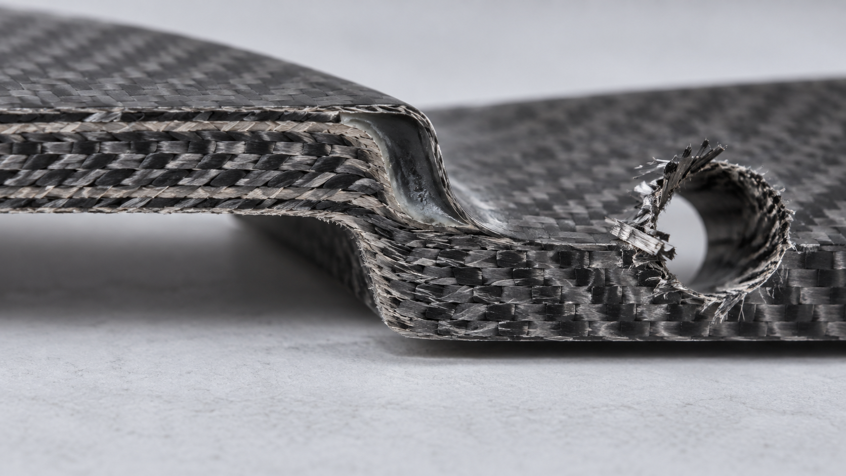
Starting from burring at one hole edge: why symmetric layup didn't save it
During assembly, a ring of fiber breakout was found at the bolt hole opening, prickly to the touch, and torque decayed after tightening. Disassembly inspection showed delamination in the hole wall, not an isolated single-hole occurrence. Tracing back to the drawing: the layup was specified as symmetric, but the hole was drilled after layup, and the hole edge landed right on the 45° ply interface. The conventional rule "symmetric layup is stable" fails here—symmetry governs global coupling, not fibers being pushed by the tool at the hole edge.
- Detection signals: burrs at the hole opening, abnormal ultrasound or tap-test sounds in the hole wall, and repeated torque decay after tightening are mostly hole-edge delamination propagating.
- Upstream decisions: whether holes are drilled afterward or left during layup, tool type and feed, and whether to add plies at the hole edge.
- More robust choice: in hole-dense areas, reserve hole locations during the layup stage, or switch to diamond-coated tools with low feed; note on the drawing the hole-edge ply reinforcement and allowable breakout range.
Boundary Condition 1: Thin Walls and Transition Zones—Meeting Total Thickness Doesn't Mean No Local Cracking
The conventional wisdom is: if local wall thickness of a carbon fiber part is no less than about 1.5 mm and rib roots have fillets, the structure is considered safe. This rule holds for homogeneous, equal-thickness laminates, but fails at thick-to-thin transition zones—total thickness meets spec, yet cracks still start from rib roots or step shoulders.
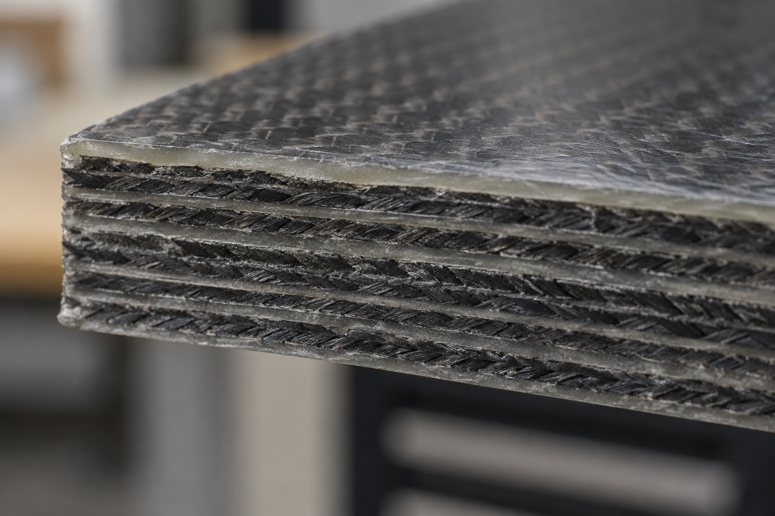
The cause is not the thickness itself, but that the layup cannot be continuous here. If the thick zone transitions to the thin zone with a direct step trim, fibers are cut and the resin carries all interlaminar shear; after curing, residual stress concentrates along this line, and delamination occurs first under assembly preload or vibration. The common industry practice is to make the transition zone a tapered layup so each ply staggers its trim, but the taper length and ply stagger amount depend on the layup design and mold; if not noted on the drawing, it must be confirmed with the process engineer and cannot be cut directly based on empirical values.
- If the transition zone length is less than 5–10 times the wall thickness difference, then prioritize changing the structure (widen the rib root or change the step to a gradual transition) rather than reinforcing by adding thickness.
- If the thin-wall zone is below 1.2 mm and still needs drilling or tapping, then move the holes to the thick zone, or switch to embedded metal inserts to carry the load.
- If only a steep transition can be retained, then keep the non-load-bearing side as the cosmetic surface and use a gentle taper on the load-bearing side; don't trim both sides at the same time.
How to catch it early
Destructive cross-section metallography can directly show whether the ply stagger is continuous; for non-destructive testing, tap for abnormal sounds or perform ultrasonic C-scan, focusing on the transition zone rather than the flat area. Detection signals are: abrupt echo changes on both sides of the transition line, or white spots near assembly holes on the first article (early delamination). Cutting one part to inspect the cross-section at the sample stage is far cheaper than reworking after the whole batch is done.

Boundary Condition 2: Low Volume and Replica Molding—What Prototype Replica Molding Can Do and What Cannot Be Assumed
The conventional advice is "for tens of parts or fewer, start with prototype replica molding." This rule fails for continuous-fiber load-bearing parts: vacuum casting uses chopped fiber or filled resin, fiber volume fraction is usually lower than laminate parts, orientation is random, and tensile and interlaminar strength are not on the same order of magnitude. Using replica-molded parts instead of autoclave laminate parts for structural validation will yield stiffness measurements that are either optimistic or simply fail to meet spec.
| Criteria | Autoclave/compression-molded laminate parts | Prototype replica-molded (vacuum-cast) parts |
|---|---|---|
| Fiber form | Continuous fiber, controllable layup | Chopped/filled, random orientation |
| Fiber volume fraction | Higher, per layup design | Usually lower, must be confirmed with the process engineer |
| Surface and detail | Affected by mold and demolding | Silicone molds can reproduce fine lines, but edges are slightly dull |
| Dimensional stability | Varies with cure shrinkage and layup | Resin cure shrinkage is more pronounced, long parts tend to warp |
| Driven by per-part cost | Mold + layup labor hours | Silicone mold lifespan + casting labor hours |
When replica tooling is the wrong choice
If a part carries load, sees fatigue, or needs fastener pull-out validation, don't assume a replica part can represent the final part—it's better suited for appearance review, assembly interference checks, and marketing samples. Detection signals: radial hairline cracks near fastener holes on the replica part, holes not aligning during assembly, and long parts warping after a few days. These situations indicate you've used an appearance part as a structural part. The more reliable approach: structural validation goes through CNC or lamination, and replica tooling is only for appearance and small-batch delivery.
Boundary condition three: surface profile tolerance, roughness, and inspection fixtures—specifying both rigidly will cause conflicts
The conventional approach is to specify both surface profile tolerance and surface roughness on the drawing, assuming the two don't interfere with each other. On carbon fiber laminated parts, this rule often fails: the tighter the surface profile tolerance requirement, the harder it is to hold surface roughness; conversely, sanding to hold roughness pushes the surface profile out of spec.
The detection signals are direct—surface profile passes when measured against the fixture mating surface, but the appearance surface feels mottled and has sanding marks; or the surface meets spec, but CMM measurement of the surface profile is out of tolerance. When both are specified rigidly without a datum, the fixture and the process will each follow their own interpretation, and end up clashing at the acceptance stage.
Define the datum surface and inspection fixture first, then allocate tolerances
- First confirm which surface is the functional datum surface (mating, sealing, assembly), and attach surface profile tolerance only to this surface;
- Then confirm the inspection fixture form: mating fixture, CMM scanning, or 3D scan comparison—different methods will yield different surface profile conclusions;
- Only then allocate roughness: specify appearance surfaces and functional surfaces separately, prioritize surface profile on functional surfaces, and allow appearance surfaces to be evaluated separately after sanding;
- When the drawing doesn't specify datum and inspection fixture, confirm with engineering first—don't default to quoting the tightest combination.
The common industry practice is to specify surface profile tolerance and roughness on separate surfaces and clearly define the inspection method; specific values need to be confirmed based on part function and drawing. If both must be tightened simultaneously, it usually means the process route needs to change (e.g., switching to compression molding or adding post-processing), and both cost and lead time will change accordingly—this needs to be laid out before tolerances are set.
Frequently Asked Questions (FAQ)
The following are the boundary questions most commonly asked during carbon fiber part quoting and drawing, and the answers all come with preconditions—don't use them as general promises.
Can ±0.1 mm be written directly on a carbon fiber part drawing?
It depends on the datum and features. After curing, laminated parts experience spring-back and demolding deformation that eats into some of the tolerance. ±0.1 is common in the industry for small flat features, but long-span surface profiles, hole positions, and thickness direction often need to be relaxed; define the datum surface and inspection fixture first, then allocate tolerances—don't apply one tolerance frame across the whole drawing.
Can hand-made replica (vacuum casting) parts be used as structural parts?
Not by default. Replica parts are mostly short-fiber filled resin, with fiber volume fraction and continuity lower than autoclave laminated parts, and load-bearing, fatigue, and temperature resistance are a notch weaker. They can be used for appearance validation, assembly trial fitting, and non-primary load-bearing parts; for load-bearing, the layup design must go through compression molding or autoclave, confirmed per drawing and process.
How do you judge whether edge chipping and delamination are scrap or repairable?
First look at location and depth: non-load-bearing areas and single-layer shallow chipping can often be repaired; load-bearing holes, multi-layer delamination, and continuous fuzzing at hole edges tend toward scrap. Detection signals are burrs at hole edges, dull tapping sound, and abnormal echoes on ultrasonic or C-scan. The criteria must be written into the drawing or inspection card—don't leave it to verbal decisions on the shop floor.
What is the minimum that should be specified on a carbon fiber part drawing?
Layup sequence and orientation, fiber volume fraction or material grade, datum surface, critical hole positions and surface profile tolerance, allowable surface defect level, and inspection method. Without layup information, neither the quote nor the finished part is controllable.
What methods are used for dimensional inspection of carbon fiber parts?
Conventionally, CMM or 3D scanning is used to compare datum surfaces and hole positions; surface profile is checked via point cloud deviation from scanning. Internal defects rely on ultrasonic or C-scan; tapping is only for rough screening. The inspection fixture and datum must be aligned with the supplier first, otherwise the data won't match up.
Key takeaways
- Symmetric layup is a good rule, but the transition zone between thin walls and local reinforcement zones is where delamination starts; the drawing must mark the transition zone, not just the total thickness.
- For concentrated hole areas, first ask "are the holes drilled or left during layup"—the two approaches have completely different tolerances and burr risks.
- For low volume (tens of parts), when prioritizing the prototype replica molding/vacuum casting route, first confirm fiber volume fraction and surface requirements; don't assume equivalence to autoclave parts.
- Don't specify profile tolerance and surface roughness as fixed at the same time: first define the assembly datum surfaces and gaging plan, then decide which surfaces can be relaxed.
- Any promise of "achievable ±0.0x" must be tied to a specific surface, specific gage, and specific process route; otherwise the drawing cannot be accepted.



