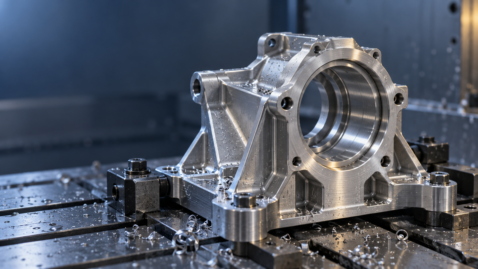
CNC Machining of Custom Robot Components: First Resolve the Gap Between Design and Manufacturing
For procurement and structural engineers working on custom robot components, the most common trouble is often not "whether this machine can mill it out." Drawings are sent out, and the quote that comes back is a good deal higher than budget; when the sample is installed on the joint, the mating surface interferes; just as low-volume production is running smoothly, the supplier says the clamping deformation of this thin-walled part cannot be controlled. The problem is mostly not machining capability, but the gap between design intent and manufacturability—the part holds up in CAD, but not necessarily on the machine tool.
In CNC machining of custom robot components, three things often appear at the same time: high complexity, cost overruns, and project delays. For parts such as joint housings, actuator parts, and end effectors, the geometry is fragmented, there are many datums, and precision requirements are concentrated on a few surfaces, yet the tolerance callouts on the entire drawing are often tightened globally. So on one side the machinist repeatedly adjusts fixturing and tool paths, while on the other side the designer feels, "I didn't even call that very tight."
The way to bridge this gap is DFM (design for manufacturing), and it must be involved early in design, not as a round of "process review" after the drawings are frozen. A common industry practice is to bring the machinist in on day one of design and look together at whether the geometry can be simplified, which surfaces tolerances should be allocated to by function, whether the material is a regularly stocked item, and whether there are graspable datums for fixturing. Once these decisions are delayed, the cost of change rises rapidly with each stage.
The following is organized along the engineering chain of design—material—tolerance—fixturing—inspection, explaining which links in CNC machining and precision manufacturing of custom robot components truly determine whether a part can be made, made stably, and made affordably. The specific values involved are all written as typical industry reference values; actual projects must combine material, geometry, and functional requirements and confirm them item by item with the machinist on the drawings.
Typical CNC Machining Checklist for Precision Robot Components
Custom robot components are rarely a single part, but a set of mutually mating precision parts. Laying out the checklist makes it easier to judge which features will drive up cost and which dimensions must be locked down, rather than discussing "robot parts" in general terms. The following is grouped by function, with the practical manufacturability concerns for each group.
Motion and transmission category: joint housings, precision shafts, precision gears, custom gearboxes
Joint housings usually also serve as bearing seats and sealing surfaces, and the design must simultaneously satisfy uniform wall thickness and visible fixturing datums. When the internal cavity is deep and the side walls are thin, separating roughing and finishing and relieving stress in between is more stable than a single pass. Precision shafts are judged by the coaxiality of the journals and mating surfaces, as well as dimensional drift after heat treatment; slender shafts also require a follower rest or segmented fixturing.
Precision gears and custom gearbox housings are key parts in the mating chain: the datum face of the gear blank, the position tolerance of the bearing bores, and the flatness of the housing joint surface all transmit to the meshing clearance. During machining, defining a unified datum first and then completing the hole system on the same piece of equipment can reduce datum transfer errors caused by multiple setups.
Support and locating category: precision bearing housings, high-precision connectors, precision brackets, structural frames
The manufacturability focus of precision bearing housings is coaxiality, end-face perpendicularity, and mating-surface roughness; if the bearing seat requires press-fitting, the bore tolerance zone must be selected according to the actual fit, rather than writing a plus-or-minus value out of habit. High-precision connectors and precision brackets often serve as connection interfaces, with short dimension chains, but the position tolerance of holes relative to the datum cannot be arbitrarily relaxed, otherwise assembly will rely on on-site fitting to compensate.
Structural frames are mostly thin-walled cavities, which are prone to elastic deformation from clamping force during fixturing and spring back after release. A feasible approach is to add process bosses or temporary supports, reduce the depth of cut per pass, and arrange a natural aging or low-temperature stress relief before finishing.
Actuation and sensing category: linear actuators, end effectors, custom grippers, sensor housings
Parts related to linear actuators are sensitive to the straightness of guide surfaces and the coaxiality of threaded or lead-screw mating sections; the machining sequence usually machines the datum face first, then the motion-pair mating surfaces. End effectors and custom grippers have complex structures with many holes and slots, and tool accessibility must be confirmed at the design stage—if an internal fillet in a deep cavity is smaller than the tool radius, the only options are to switch to a smaller tool or change the design.
Sensor housings and precision enclosures must both protect internal components and ensure accurate mounting hole positions and window locations. For thin-walled housings, it is recommended to keep the minimum wall thickness above the common industry reference value (approximately ≥0.5 mm), and to avoid cutting large holes in load-bearing areas that weaken stiffness.
The value of this list lies in comparison: first confirm which category your part falls into, then determine what its key features are. For parts with similar functions, manufacturability risks often concentrate in the same one or two places—mating surfaces, wall thickness, and fixturing datum. CNC machining capabilities cover precision parts in metal and plastic; for the process path specific to robot components, you can view the machinable range and tolerance specifications on the CNC machining capabilities page.
DFM upfront: geometry, tolerance, and fixturing checkpoints for robot components
The cost of custom robot components is mostly determined at the design stage. If roughing starts before the part is fully drawn, then changing the geometry once later will scrap all the previous toolpaths, fixtures, and gauges. A common industry practice is to put DFM (design for manufacturability) on day one of design: first check whether the geometry can be simplified, whether tolerances are allocated by function, and whether there is a datum for fixturing, then decide whether to release material. This is especially true for CNC machining of robot components—joint housings, actuator parts, and end effector structures are compact, and the space left for tools and fixtures is inherently narrow.
Geometry simplification: first check whether the tool can get in
The design intent is function, but manufacturing looks at tool accessibility. Deep cavities, narrow slots, and internal right angles are often the real source of cost and lead time. A feasible approach is to enlarge internal cavity fillets to more than the tool radius, change sharp corners on non-functional surfaces to fillets, and split deep cavities that must be retained into two parts for assembly. Common industry reference values: minimum internal fillet radius approximately ≥0.5 mm, recommended minimum hole diameter approximately ≥1.0 mm; hole depth-to-diameter ratio is usually controlled at ≤10:1, ideally ≤5:1. These are only starting points for judgment; the specifics also depend on material, tool overhang, and chip evacuation conditions.
Thin-walled parts also need to be clarified in advance. Robot components commonly use aluminum alloy to reduce weight, and excessively thin walls will cause chatter and deformation under clamping and cutting forces. The common industry lower limit is ≥0.5 mm, but for thin-walled areas, what deserves more attention is the support method and toolpath sequence, not just that number.
Tolerances and surface treatment: allocate by function, do not tighten globally
Giving every dimension on a drawing ±0.01 mm is a common cost trap. Tolerances should be allocated by function: bearing seats, mating surfaces, and gear meshing surfaces need to be tightened; non-mating structural surfaces and clearance surfaces can be relaxed. The same applies to surface treatment—sealing surfaces and sliding surfaces require low roughness, appearance surfaces are determined by appearance requirements, and internal support surfaces do not need polishing. Typical industry reference values: CNC machining tolerance approximately ±0.025–0.125 mm, precision surface roughness approximately Ra 0.4–0.8 µm, standard surface approximately Ra 1.6–3.2 µm. These are common industry ranges; specific projects must be confirmed with the supplier based on material and geometry.
| Design elements | Common reference values | Reasons and advantages |
|---|---|---|
| Minimum internal fillet radius | Approx. ≥0.5 mm | Allows standard end mills to clear corners, reducing EDM or special tooling |
| Recommended minimum hole diameter | Approx. ≥1.0 mm | Reduces the risk of drill breakage and facilitates chip evacuation and cooling |
| Hole depth-to-diameter ratio | Approx. ≤10:1, ideally ≤5:1 | Deep holes have poor chip evacuation and tend to deviate, requiring high rigidity in fixturing and tooling |
| Threaded hole depth | Approx. ≤3 times the thread diameter | Taps are less likely to break, and the pilot hole depth is controllable |
| Minimum wall thickness | Approx. ≥0.5 mm | Reduces deformation and chatter caused by cutting forces |
Fixturing and workholding: datums must be clearly specified on the drawing
Many precision issues in robotic components stem from fixturing rather than the machine tool. If a part has only one clampable face, or critical dimensions hang at the end far from the datum, special fixtures or soft jaws are needed to compensate during machining. What can be done at the design stage: specify clear primary and secondary datums, and give datum faces sufficient area; avoid critical features on thin-walled overhangs; if volume production is expected, discuss in advance the feasibility of completing multiple faces in a single setup to reduce repeated locating errors.
DFM checkpoints don't need to be a long checklist. Run through these four categories first—geometry, tolerances and surfaces, materials and inventory, and fixturing and workholding—and the CNC machining quote and first-article risk for a robot assembly become much clearer. How to choose materials and how to sequence heat treatment can be discussed next.
Materials and Heat Treatment: The Technical Commonality from Precision Molds to Robot Parts
In CNC machining of custom robot assemblies, material selection is rarely about "whichever is cheapest." Parts like joint housings, actuator components, end effectors, and precision bearing seats simultaneously bear loads, vibration, reciprocating motion, and assembly precision requirements. The material determines the strength-to-weight ratio, wear resistance, and dimensional stability, and also determines how subsequent heat treatment and the machining route are sequenced. When Zhenyu Technology disclosed its robot precision components business, it noted that robot precision components and precision mold manufacturing share technical commonality in materials, heat treatment, fabrication processes, dedicated equipment development, assembly, and precision requirements—in other words, a factory that has done precision molds accumulates the same set of capabilities in material batch control, heat treatment distortion control, and assembly precision.
Selection Logic for Aluminum Alloys, Stainless Steel, Titanium Alloys, and Engineering Plastics
The vast majority of robot structural parts and joint housings use aluminum alloys, typically 6061-T6 or 7075-T6. 6061 has good machinability, good weldability, and controllable cost, making it suitable for frames, brackets, and housings; 7075 has high strength but is more prone to tool deflection and distortion during cutting, so thin-walled parts require sequential operations and controlled cutting depth. Stainless steel (such as 304, 17-4PH) is mostly used for wear-resistant shafts, gears, and applications requiring corrosion resistance; it has a pronounced work-hardening tendency and causes rapid tool wear, so drilling and tapping require controlled cutting speeds. Titanium alloys (such as TC4) have a high strength-to-weight ratio, but poor thermal conductivity and large elastic recovery mean thin walls and deep cavities tend to cause tool heating and part distortion; the industry typically uses them only where weight reduction is genuinely needed and the budget allows.
Engineering plastics are commonly found in sensor housings, insulating parts, and light-load grippers. POM, PEEK, and PA each have trade-offs: POM is dimensionally stable and easy to machine, while PEEK is temperature- and wear-resistant but expensive. The coefficient of thermal expansion of engineering plastics is an order of magnitude larger than that of metals, so fit clearances must be recalculated according to operating temperature and cannot simply copy the tolerances of metal parts.
Heat Treatment and Stress Relief: A Prerequisite for Dimensional Stability
Robot parts are sensitive to dimensional stability because, under reciprocating motion and high cycle rates, residual stress release causes mating surfaces to gradually shift. For aluminum parts, scheduling stress relief after rough machining and then performing semi-finish and finish machining is a common practice; for steel and titanium parts, annealing, solution treatment, aging, or quenching and tempering are selected according to the material. The heat treatment sequence must be planned together with the machining sequence: heat treatment first, then finish machining, so that heat treatment distortion is absorbed by the semi-finish operation rather than left to the assembly floor.
There is an easily overlooked collaboration point here: heat treatment is not finished once it is outsourced. Hardness, distortion amount, and surface condition need to come back to the drawing with furnace reports or sampling data, and the supplier and the machining party must agree on the same technical requirements. A common industry practice is to perform an additional dimensional inspection on critical mating surfaces after heat treatment to confirm that distortion is within the repairable range before proceeding to finish machining.
Materials and Inventory: Real-World Constraints in the DFM Stage
When designers select material grades, they often consider only mechanical properties and ignore the standard specifications of plate and bar stock. If a 20 mm thick 7075 plate is not in regular inventory, it may mean a longer material preparation cycle or higher material utilization loss. Listing "available standard grades and specifications" in DFM feedback is easier than changing the drawing afterward. For small-batch custom robot assemblies, converging material grades to 2–3 types reduces procurement complexity and also makes heat treatment and machining parameters easier to standardize.
If the project is still in the prototype stage, you can use 3D printing to first validate geometry and assembly, then use CNC machining for functional parts. When the material transitions from plastic to aluminum alloy, mating surface tolerances need to be redistributed and cannot simply carry over from the prototype tolerances. When you need to check available grades, the materials library can serve as a starting point.
Tolerances, Surfaces, and Inspection: How to Allocate Precision by Function in Robot Assemblies
Precision in robot assemblies is not better the higher it is. Marking an entire drawing as ±0.01 mm only increases machining cost, adds setups, and raises the scrap rate, while the actual motion precision of the joint may not improve. What really determines assembly success is often just a few surfaces: bearing seats, mating surfaces, gear meshing surfaces, and actuator mounting surfaces. The remaining non-mating surfaces can be handled with free tolerances or general tolerances. This section is about allocating precision by function—first determine which dimensions carry motion and load, then decide the tolerance zone and surface roughness, and finally lock in the conclusion with inspection methods.
Tighten Critical Dimensions, Loosen Non-Mating Surfaces
Take a robot joint housing as an example. The coaxiality of the bearing bore, the perpendicularity of the bore to the end face, and the flatness of the mounting flange directly determine bearing preload and backlash, so they are dimensions that must be tightened. The outer contour of the housing, cable routing grooves, and non-load-bearing lightening cavities, as long as they do not affect assembly and stiffness, have no reason to require precision-grade tolerances. The judgment sequence is usually: Does this dimension participate in motion transmission? Does it affect assembly interchangeability? Does it carry alternating loads? Only if one of these three questions is answered "yes" is it worth tightening.
Common industry reference values for CNC machining tolerances generally fall in the range of ±0.025–0.125 mm; precision mating surfaces often fall at the tighter end, while general structural surfaces fall closer to the looser end. This is only a starting point for judgment, not a promised value—what can actually be achieved consistently depends on the material, part rigidity, fixturing method, and toolpath, and must be confirmed item by item with the machining party during drawing review.
Surface Roughness Graded by Function
Surface roughness is likewise graded by function. Bearing mating surfaces, sealing surfaces, and sliding guideway surfaces usually require finer surfaces, with a typical industry reference value of Ra 0.4–0.8 µm; general mounting surfaces and structural exterior surfaces commonly only need Ra 1.6–3.2 µm. Finer surfaces often require fine milling, grinding, or lapping, which increases both processes and labor time. If a surface is neither a mating nor a sealing surface, specifying it as Ra 0.4 µm is a typical case of over-requirement.
| General structural dimension tolerance | ±0.025–0.125 mm | Housing contours, brackets, non-mating mounting surfaces |
| Precision mating surface roughness | Ra 0.4–0.8 µm | Bearing seats, sealing surfaces, sliding surfaces |
| Standard surface roughness | Ra 1.6–3.2 µm | General mounting surfaces, exposed structural surfaces |
| Minimum internal fillet radius | ≥0.5 mm | Internal cavity corners, to facilitate tool passage |
| Recommended minimum hole diameter | ≥1.0 mm | Small holes, oil passages, locating holes |
| Hole depth-to-diameter ratio | ≤10:1, ideally ≤5:1 | Deep-hole drilling and chip evacuation |
| Threaded hole depth | ≤ 3 times the thread diameter | Threaded connection strength and tapping accessibility |
| Minimum wall thickness | ≥0.5 mm | Thin-wall housings, lightweight structures |
The purpose of this table is to let designers check it over before dimensioning: Have you made any hole with a depth-to-diameter ratio of 15:1? Have you required a precision fit on a thin wall? These features aren't impossible to produce, but they significantly drive up cost and risk. Making manufacturability judgments before dimensioning is easier than having the machine shop raise issues after the fact.
Inspection: CMM reports, first article and datum consistency
Tolerances are specified, but they still have to be measurable. Inspection of robotic components typically revolves around coordinate measuring machines (CMMs), and the key isn't "how many dimensions were measured" but whether the datums are consistent with the design intent. If the drawing defines coaxiality using a combined A-B datum, but each is set up separately during inspection, the data won't match up, and problems only surface at assembly.
The standard practice is: perform full dimensional and geometric tolerance inspection on the first article and issue a CMM report; during production, carry out process sampling inspection on critical dimensions, combined with dedicated gauges to control mating features such as bearing seats and mounting hole locations. The gauges themselves must also be aligned with the drawing datums, otherwise the sampling data merely "looks qualified." For small-batch custom robotic components, the first article report is often more critical than process data—it verifies whether the process route itself can stably reproduce the design intent.
If a drawing has all critical tolerances, datums, and surface requirements in place, the machine shop can provide more accurate process feedback and inspection plans. Conversely, a drawing with vague specifications usually means repeated communication and rework. Allocating precision clearly by function is the prerequisite for making subsequent inspection meaningful.
From prototype to small batch: supplier collaboration and distributed manufacturing for robotic components
For custom CNC machining of robotic components, the prototype stage is the easiest to validate; the hard part is the stretch between prototype and small batch. Prototypes can be hand-fitted, clamped one at a time, and set up individually, with tolerances found on the spot by the machinist; once the quantity goes from 1 piece to 50 or 200 pieces, the fixturing plan, tool life, inspection cadence, and batch consistency all get exposed at once. Choosing a supplier is essentially choosing an engineering capability that can stably replicate the design intent into every part.
Look at DFM feedback capability, not the machine list first
A supplier willing to point out before quoting that "this internal fillet can't be reached by the tool," "this hole's depth-to-diameter ratio is too large and chip evacuation will be risky," or "this datum is inconsistent with the assembly datum" is more valuable than one that lists a long string of equipment models. Robotic precision components often have complex structures and many mating surfaces, and DFM feedback can absorb later rework back into the drawing stage. When evaluating, you can give the same drawing to two or three suppliers for feedback and see who raises real issues at the geometry and fixturing level, and who merely replies "we can make it."
Inspection reports and fixturing plans must correspond to the drawing datums
At the small-batch stage, the supplier should be able to provide first article inspection and process sampling records, and the datums on the CMM report must be consistent with the drawing datums, rather than setting up a separate set of datums that are convenient for measurement. The fixturing plan should also be clarified: what support is used for thin-wall parts like joint housings, whether custom soft jaws or contoured fixtures are made, and whether secondary alignment is needed after heat treatment. If fixturing is inconsistent, coaxiality and position tolerance can't be stable. For specifics on CNC machining capabilities and the types of parts that can be handled, you can cross-check on the CNC machining capabilities page.
The geographic distribution of supply chains is also changing. AMC Robotics has set up a subsidiary in Vietnam for robot manufacturing, and the reasons given are straightforward: cost efficiency, tariff stability, skilled labor, and the local electronics manufacturing and precision assembly ecosystem. These four points apply equally to evaluating distributed supply for robotic components: beyond cost, it's even more important to see whether the local area has the supporting infrastructure for precision assembly, and whether DFM communication, change confirmation, and inspection data transfer will slow down during cross-regional collaboration. Distributed manufacturing isn't just about sending out drawings and being done; the pace of collaboration is itself part of the cost.
When transitioning from prototype to small-batch production, the three things most worth confirming first are: whether the fixturing has been locked in, whether the inspection datum matches the drawing, and whether heat treatment and stress-relief operations have been scheduled into the process route. Once these three are settled, batch consistency has a foundation. When you need to verify manufacturability and the process route against the drawing, you can submit CAD through the classic quote entry point, and the engineering side will provide feedback on fixturing and tolerances.
Early signals in humanoid robot precision parts: linear actuators and planetary roller screws
The joint housings, end effectors, and precision gears discussed earlier are all robot components that are already in stable volume production. What truly deserves separate attention is the batch of new parts brought about by humanoid robots—linear actuator modules and inverted planetary roller screws. They place requirements on CNC machining and precision manufacturing of custom robot components that differ somewhat from those of traditional industrial robots.
What signals did Zhenyu Technology disclose
In its December 2025 investor relations disclosure, Zhenyu Technology provided a relatively specific set of progress updates: its linear actuator modules and inverted planetary roller screws have already been directly connected with major overseas customers, and it has basically achieved full coverage of batch supply, sample delivery, and technical exchange with domestic humanoid robot OEMs, with some products already delivered in small batches. At the same time, the company clearly stated that this portion of products accounts for a relatively small proportion of the company's overall revenue.
This "facts + risk warning" approach is worth noting, because it explains two things at once: first, precision machining capability is indeed migrating from precision molds and automotive parts toward robot parts; second, this migration is still at an early stage and is not yet sufficient to treat it as a mature mass-production track. It is easy to get excited when reading "batch supply," and only when reading "accounts for a relatively small proportion of revenue" do you return to reality.
What does shared technical origin mean
Zhenyu Technology itself stated the migration logic very plainly in its disclosure: robot precision components and precision mold manufacturing share a common technical origin in materials, heat treatment, fabrication processes, dedicated equipment development, assembly, and precision requirements. In other words, the difficulty of parts such as planetary roller screws does not lie in whether they are "robot-specific," but in whether basic processes such as thread grinding, heat-treatment deformation control, and assembly precision can be performed stably.
This is also why the CNC machining capability for custom robot components ultimately comes down to the same engineering chain: material selection, heat treatment scheduling, tolerance allocation, fixturing plans, and inspection datums. The DFM front-loading, function-based precision allocation, and CMM inspection discussed in previous sections are reflected more intensively in these types of parts, rather than being replaced by a new set of methods.
How to calibrate the interpretation of such signals
Whether planetary roller screws have already entered large-scale mass production cannot yet be answered affirmatively based on currently public information. There is a clear distance between small-batch delivery and batch supply; the latter involves cycle time, yield, the cost curve, and supply chain stability. For teams that need custom robot components, a more practical way to judge is to align your own part requirements with a supplier's actual process capabilities, rather than inferring from industry news that you can immediately obtain capacity of the same specifications.
The migration of precision manufacturing capability is real, but the pace of migration follows the parts, not the news. The requirements of linear actuators and planetary roller screws for CNC machining, grinding, heat treatment, and assembly need to be confirmed one by one by returning to specific drawings and tolerance bands.
FAQ: CNC machining and precision manufacturing of custom robot components
The following are the questions most frequently asked after reading this article. The answers aim to provide verifiable bases for judgment rather than promises. Specific projects still need to be confirmed item by item with the engineering team according to drawings, materials, and functional requirements.
What materials are generally used for robot joint housings?
There is no universal answer; it depends on the load path, weight budget, and heat dissipation requirements. In the industry, 6061-T6 or 7075 aluminum alloy is common because of its good strength-to-weight ratio, stable machinability, and wear resistance after anodizing; stainless steel or titanium alloy is used in heavy-load or high-stiffness applications, but machining hours and tool wear increase noticeably. Engineering plastics such as POM and PEEK are mostly used for light-load joints, sensor housings, or insulating parts. When selecting materials, also confirm whether the blank specifications are regularly stocked—non-standard sizes will lengthen the material preparation stage.
Do tolerances for robot components need to be tightened globally?
No, and global tightening is usually the main cause of cost overruns. The correct approach is function-based allocation: tighten bearing seats, mating surfaces, and gear meshing surfaces according to assembly requirements, and relax non-mating surfaces and cosmetic surfaces. Typical industry CNC machining tolerances are about ±0.025–0.125 mm, precision surfaces about Ra 0.4–0.8 µm, and standard surfaces about Ra 1.6–3.2 µm, all for reference. Clearly marking datums and critical dimensions on the drawing is more effective than broadly writing "all ±0.01."
What materials need to be provided before small-batch trial production?
At minimum, you need: a 3D model (STEP preferred), 2D drawings (with key dimensions, tolerances, datums, and surface requirements marked), material and heat treatment requirements, and quantity and purpose (prototype validation or functional testing). If there are assembly relationships, providing mating parts or assembly drawings can significantly reduce back-and-forth confirmation. If reverse engineering is involved, you can first perform a 3D scan to obtain a point cloud and then reconstruct the model. The more complete the materials, the more specific the DFM feedback.
Will heat treatment affect the dimensions of robot parts?
Yes. Processes such as quenching, aging, and stress relief can all introduce deformation or dimensional drift, especially for thin-walled housings, long shafts, and frame-type parts. A common approach is to schedule heat treatment between rough machining and finish machining, leaving finishing allowance, and adding stress-relief annealing when necessary. Zhenyu Technology mentioned in its disclosures that robot precision components and precision molds share a common technical origin in materials, heat treatment, and manufacturing processes—this also shows that heat treatment is not an auxiliary process but a link in the precision chain. Whether the final dimensions are stable must be based on post-machining inspection data.
Have parts like planetary roller screws already entered mass production?
Currently, the public information shows early-stage signals, not large-scale mass production. Zhenyu Technology disclosed that its linear actuator modules and inverted planetary roller screws have directly connected with major overseas customers, and that domestic humanoid robot OEMs have basically achieved full coverage of batch supply, sample delivery, and technical exchanges, with some products delivered in small batches, but accounting for a relatively small proportion of the company's overall revenue. The machining difficulties for such parts are concentrated in thread grinding, coaxiality, and heat treatment stability. Whether stable delivery can be achieved still depends on the specific production line and inspection capabilities, and projects should not be planned on the basis that they are already in mature mass production.
Key takeaways
- The core contradiction in custom robot components is the gap between design intent and manufacturability; DFM should be involved early in design, rather than discovering problems only after quoting.
- Typical precision robot parts include joint housings, actuator parts, end effectors, gears, bearing seats, sensor housings, structural frames, etc., each with different manufacturability priorities.
- Tolerances and surface treatment should be allocated by function rather than tightened globally; typical industry CNC tolerances are about ±0.025–0.125 mm, and precision surfaces about Ra 0.4–0.8 µm, both reference values that must be confirmed according to material and geometry.
- Materials and heat treatment directly affect machinability, wear resistance, and dimensional stability; robot parts and precision molds share technical commonality in materials, heat treatment, and processes.
- Signals of low-volume delivery have appeared for humanoid robot linear actuators, planetary roller screws, etc., but the overall field is still early and accounts for a small share of related companies' revenue, so it should not be overinterpreted.



