Manufacturing Process Guide
How to Quote and Inspect Sheet Metal Fabrication: A Practical Checklist for Engineers and Buyers
9/11/2026, 19:044 views
From a single bent-part drawing to volume delivery, the cost, process boundaries, and inspection points of sheet metal fabrication are often decided at the quoting stage. This article breaks down the decision logic across four stages—cutting, bending, welding, and surface treatment—and provides a question checklist you can use when communicating with suppliers.
Why quotes for the same bent-part drawing can differ by double across three suppliers
Send the same bent-part drawing to three suppliers, and the quotes that come back may differ by double. The drawing hasn't changed, the material hasn't changed—the difference is often hidden in process boundaries: one supplier uses laser cutting for blanking and bends parts individually, while another switches to stamping dies and amortizes the cost; at the weld, one estimates based on spot welding, while another estimates based on full welding and includes grinding labor hours; whether surface treatment is outsourced or done in-house can also widen the price gap. Quotes usually list only a total price without these premises, making it hard for buyers to judge which supplier is reasonably expensive.
To see the price difference clearly, sheet metal parts must be broken down into four core processes—cutting and blanking, bending, welding, and surface treatment—and compared item by item. The following expands on these four stages, explaining the cost focus of each stage and where the design side can align in advance.
The four core processes of sheet metal fabrication and their cost focuses
When quotes for the same drawing differ by double, the difference is often not in the material unit price, but in the process path choices across the four operations. Only by breaking down the cost can engineers judge which quote is reasonable and which supplier is betting you don't understand.
Blanking: the trade-off between laser cutting and stamping
Blanking determines sheet utilization and per-part labor hours. Laser cutting requires no mold and is suitable for prototyping and small-to-medium batches, but cutting speed decreases with sheet thickness, and thick sheets with dense contours significantly lengthen labor hours; stamping requires a mold, with low per-part cost but high upfront investment, suitable for parts with stable shapes and large volumes. Quote variables are mainly sheet thickness, total contour length, number of holes, and nesting method. What the design side can optimize: reduce unnecessary irregular contours, unify hole diameters, and avoid excessively small internal fillets to make nesting more compact.
Bending: the number of bends and tooling determine labor hours
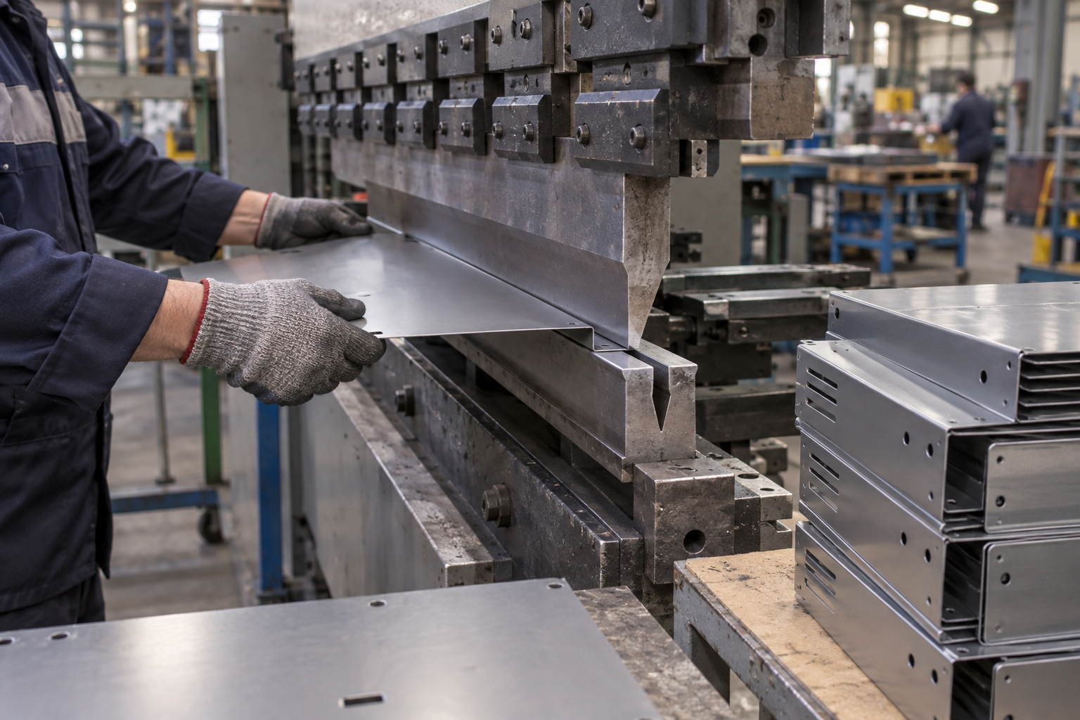
Bending is the most easily underestimated stage in sheet metal quoting. Each additional bend adds another positioning, tool change, or flip, and labor hours rise accordingly; an unreasonable bending sequence can also cause interference and require additional operations to remedy. Regarding tooling, V-groove width and punch radius must match the sheet thickness, and special angles or deep bends may require dedicated tooling. What the design side can optimize: reduce the number of bends while meeting functional requirements, unify bend angles and radii, and avoid bend lines being too close to holes or notches.
Welding: labor hour differences between spot welding and full welding
Spot welding is used for positioning and light-load connections, with fast speed and low heat input; full welding is used for parts requiring sealing, load bearing, or high appearance standards, requiring more labor hours and more prone to deformation, often requiring straightening or subsequent machining. Quote variables include weld seam length, welding method, and whether grinding and inspection are required. What the design side can optimize: use spot welding or stitch welding instead of full welding at non-critical connections, place weld seams on non-appearance surfaces, and reduce post-weld straightening needs.
Surface treatment: the hidden costs of the outsourcing stage
Painting, anodizing, electroplating, etc. are usually completed by outsourcing, and cost and lead time are affected by color, film thickness requirements, racking method, and batch size. Small batches with multiple colors significantly raise unit prices because color changes and rack preparation cannot be amortized. What the design side can optimize: unify colors and surface requirements as much as possible, avoid mixing too many specifications in the same batch, and clearly specify appearance and non-appearance surfaces on the drawing to reduce rework.
The three pitfalls designers most easily fall into: bend radius, hole edge distance, and developed dimensions
The most common rework at the quoting stage is often not that the supplier cannot make it, but that the drawing itself leaves no process margin. The following three details are most likely to cause disputes at the first article stage.
The relationship between bend radius and sheet thickness
The internal bend radius should generally not be smaller than the sheet thickness; otherwise the outer material is easily torn, especially on stainless steel or high-strength steel. If the internal angle is specified too small in design, the supplier will either suggest enlarging it or switch to a softer material, and the quote will naturally rise. It is recommended to confirm the acceptable bend radius range with the process side at the drawing stage, rather than changing the drawing after the first article cracks.
Distance from holes to the bend line
If a hole is too close to the bend line, the hole will be stretched and deformed during bending, and may even affect subsequent assembly. As a rule of thumb, the distance from the hole edge to the bend line should leave sufficient margin; the specific value is related to sheet thickness and hole diameter, so it is recommended to mark it clearly on the drawing or directly confirm with the process side. Many first article rejections happen at this step—the 3D model looks fine, but after unfolding, the hole positions have already shifted.
Differences between the developed drawing and the 3D model
The 3D model gives the formed state, while cutting and blanking require the developed drawing. Different suppliers may use different bend deduction factors, and the same drawing will have dimensional differences after unfolding. If only the 3D model is provided without the developed drawing or bending parameters, each party may calculate differently during quoting, and the first article may not match. The safer approach is to align the bend deduction rules with the process side at the drawing stage, or directly provide the developed drawing for verification.
From prototyping to mass production: how to choose between sheet metal, CNC, and injection molding
At the small-batch stage, process selection often determines subsequent mold modification costs. Sheet metal is suitable for structural parts and enclosures: strength is obtained through bending ribs and welding, per-part cost decreases gradually with quantity, and design changes only require modifying programs and bending sequences without touching molds. CNC is suitable for high-precision functional parts such as bearing seats, mating surfaces, and sealing grooves, where one setup can ensure positional relationships, but material utilization is low, and the larger the quantity, the less cost-effective it becomes. 3D printing is suitable for quickly verifying assembly and appearance, and silicone molding can provide samples close to injection-molded appearance at the small-batch stage.
When should you switch from sheet metal to injection molding? The unit cost advantage of injection molding only becomes apparent when the annual demand for the enclosure reaches a certain scale and the shape begins to feature complex curved surfaces, snap fits, and internal ribs, but you must first bear the tooling investment. If the quantity is only in the tens to hundreds, sheet metal or prototype vacuum casting is usually more reliable. Another common combination is: the main body is formed by sheet metal or injection molding, and key mating surfaces are supplementarily machined by CNC, balancing cost and precision. It is recommended to share the quantity, assembly relationships, and appearance requirements with the process provider at the drawing stage, and let engineering evaluate the path.
Frequently Asked Questions
Questions during the quotation and acceptance stages often center on the completeness of documentation, inspection criteria, and outsourced processes. The following summarizes the most common questions raised by engineers and purchasing staff; the answers remain cautious, and specific metrics should be confirmed item by item with the process provider.
What information is needed to quote sheet metal parts?
Typically, a 3D model or 2D flat pattern, sheet thickness and material, surface treatment requirements, quantity, and batch are needed. If there are critical mating dimensions or appearance surfaces, it is recommended to mark them on the drawing and specify the inspection method. The more complete the information, the closer the quote will be to the actual processing cost, and the fewer subsequent changes there will be.
How should bent parts be inspected upon arrival?
It is recommended to first verify the material, sheet thickness, and surface treatment, then check the bend angle, bend direction, and the relative positions of holes. Prioritize measuring dimensions that affect assembly, and if necessary, recheck with fixtures or a CMM. Scratches, dents, and burrs on appearance surfaces should also be clearly listed in the acceptance checklist.
How can welding distortion be controlled?
You can approach this from both structural design and process: reduce weld length and heat input, arrange welds symmetrically, and add positioning fixtures or post-weld straightening when necessary. For dimensionally sensitive frame parts, it is recommended to discuss the welding sequence and fixing method with the process provider during the prototyping stage.
Will surface treatment significantly lengthen the outsourcing cycle?
Painting, anodizing, electroplating, etc. usually belong to outsourced processes, and the cycle is affected by the process type, color batch, and capacity. It is recommended to reserve buffer time in the project schedule and confirm with the supplier whether they will be processed in the same batch, to avoid color differences caused by batching.
Is it worth making tooling for small-batch sheet metal parts?
Sheet metal mainly involves cutting, bending, and welding, and usually does not require molds in the injection molding sense; whether to invest in dedicated fixtures or gauges depends on the batch size, precision requirements, and expectations of repeat orders. When the quantity is small, you can first verify the structure with manual or general-purpose fixtures, then evaluate dedicated tooling.
Key takeaways
- Sheet metal cost is mainly composed of four parts: cutting path, number of bends, welding labor hours, and surface treatment. Confirming these four items before quoting can significantly reduce back-and-forth communication.
- Bend radius, hole edge distance, and developed dimensions are the three details most likely to cause rework on the design side. It is recommended to align with the process side at the drawing stage.
- The focus of inspection for welded parts is usually not individual part dimensions, but post-weld deformation and assembly datums. When necessary, use gauges or scanning comparison to confirm.
- At the small-batch stage, CNC or 3D printing can be used for functional verification, then switch to sheet metal or injection molding for mass production, avoiding premature investment in molds and tooling.