First ask what questions the prototype must answer, then discuss the process
Give the same drawing to three suppliers and you may get three completely different approaches. The problem is often not the supplier, but the requirement itself not being clearly stated: what questions is this prototype actually supposed to answer?
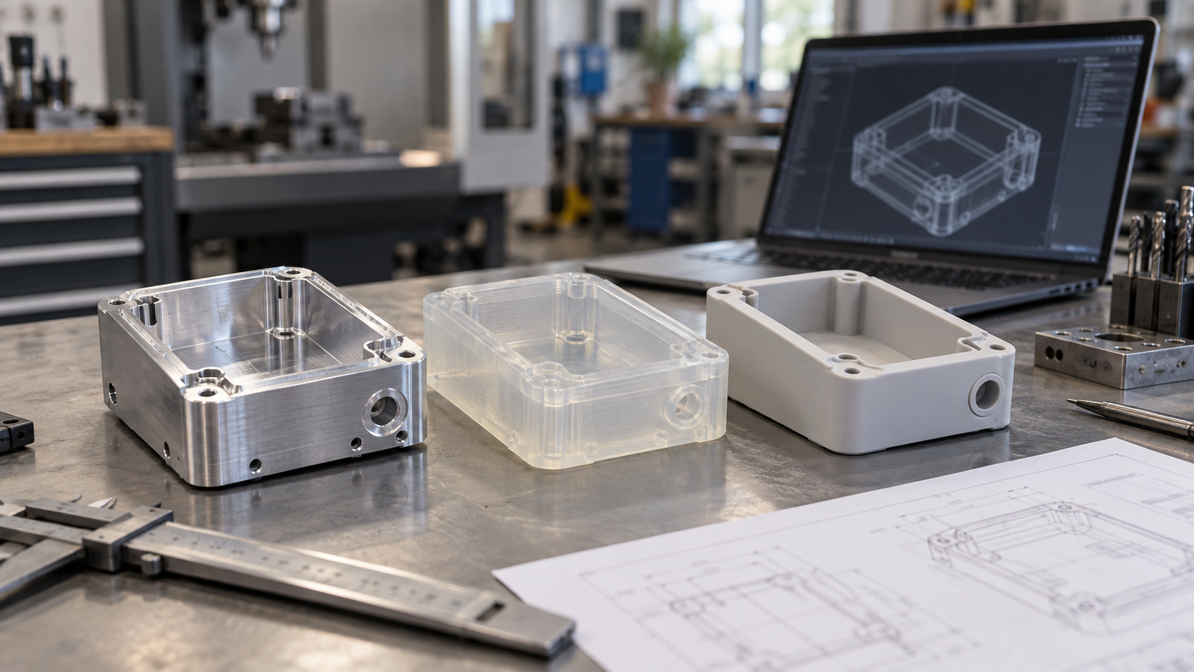
The three common goals correspond to very different process paths: assembly verification cares about hole positions, mating surfaces, threads, and structural strength, and usually leans toward CNC machining; appearance review cares about surfaces, parting lines, surface texture, and color, making 3D printing or prototype casting more suitable; small-batch trial assembly requires weighing quantity, unit cost, and the subsequent mass-production process, where vacuum casting or sheet metal often comes closer to the real delivery state.
The recommended decision order is: define the problem first → then choose the process → finally choose the material and surface treatment. Reverse the order and it is easy to end up “using the wrong process to verify a problem it inherently cannot verify,” such as using a printed part to evaluate the assembly feel of an injection-molded part, or using a CNC part to judge the appearance of mass-produced injection molding.
This article discusses the judgment logic for process selection and does not cover specific tolerance values, certifications, or lead-time commitments—these need to be confirmed item by item with the engineering team based on the drawing and application.
CNC, 3D printing, vacuum casting: the boundaries of the three mainstream prototyping processes
There is no “best” prototyping process, only the one that “best matches the current problem.” Below, the three mainstream paths are broken down, each with a one-sentence judgment to help you quickly set the tone in a drawing review meeting.
CNC machining: when you need fit, threads, and strength, consider it first
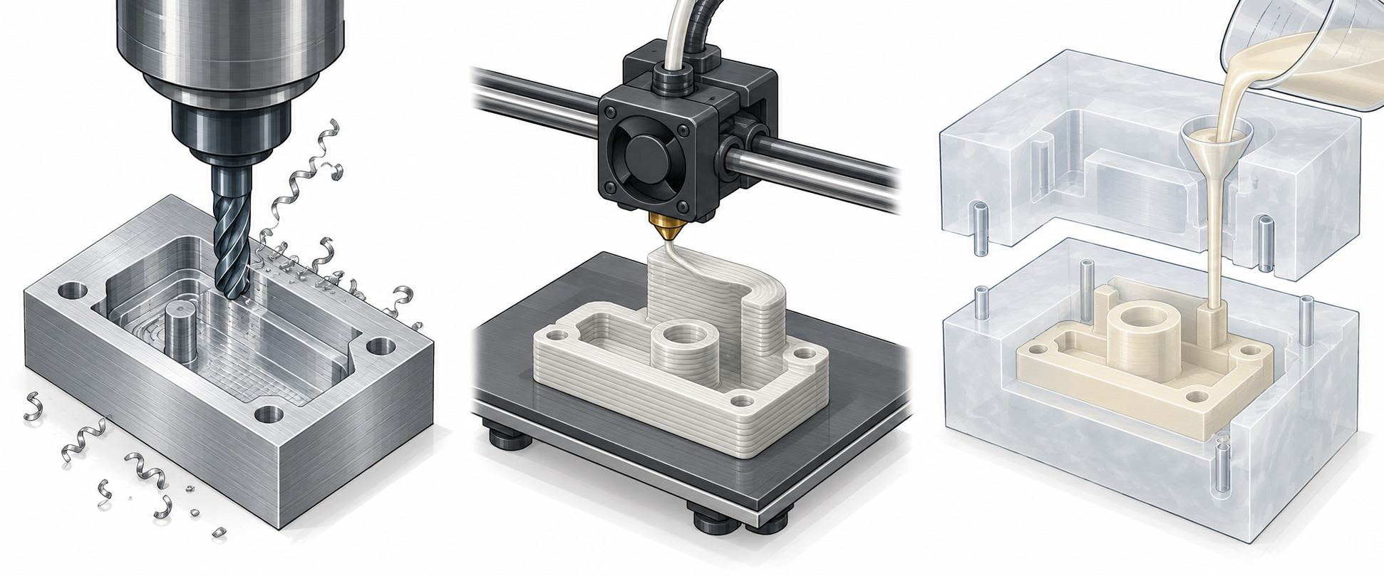
CNC machining forms parts by subtracting material from a solid block of metal or plastic, making it suitable for structural parts, assembly parts, and parts requiring real threads and mating surfaces. Metal parts such as aluminum alloy and stainless steel, and plastic parts such as POM, ABS, and PC, can all be machined directly into parts close to their final use state for structural strength verification and assembly interference checks.
When to prioritize it: when a part has clear mating dimensions, requires tapping or press-fit nuts, needs drop or load testing, or when subsequent small batches are still planned to use machining, a CNC prototype carries the most information. The limitations are that complex internal cavities, deep narrow slots, and extremely thin-wall structures are difficult to machine, material utilization is low, and unit cost is relatively high.
3D printing: complex geometry and frequent iteration—get it running first
3D printing is additive manufacturing, forming directly from a digital model, and is suitable for rapid prototyping and small-batch trial production. Internal channels, hollow lattices, and integrated irregular structures—geometries that CNC struggles with—can often be formed in one pass by printing, and reprinting after a drawing change is fast, making it suitable for multiple rounds of iteration.
When to prioritize it: when the design is still changing rapidly, the shape and assembly relationships need to be verified, and the part geometry is complex with no extreme absolute strength requirement, printing is the most efficient starting point. The limitations are interlayer bonding and anisotropy; load-bearing parts, precision mating surfaces, and holes requiring tapping usually need machining allowance or a switch to CNC post-processing.
Prototype casting (vacuum casting): for small batches of appearance parts, use it when the quantity is in the middle
Prototype casting first uses CNC or 3D printing to make a master pattern, then produces a silicone mold and replicates small batches of parts through vacuum casting. Its value lies in surface texture and color: it can produce appearance surfaces close to injection-molded parts and can adjust color and hardness, making it suitable for appearance review, market samples, and small-batch trial assembly.
When to prioritize it: when the quantity has exceeded single-piece prototyping but has not yet reached the level for a steel mold, and the part’s main requirements are appearance, feel, and color, casting is a common choice. The limitations are that silicone molds have a limited lifespan, dimensional stability is inferior to injection molding, and structural load-bearing parts generally do not use it for final verification.
The prototyping logic for sheet metal parts is a bit different
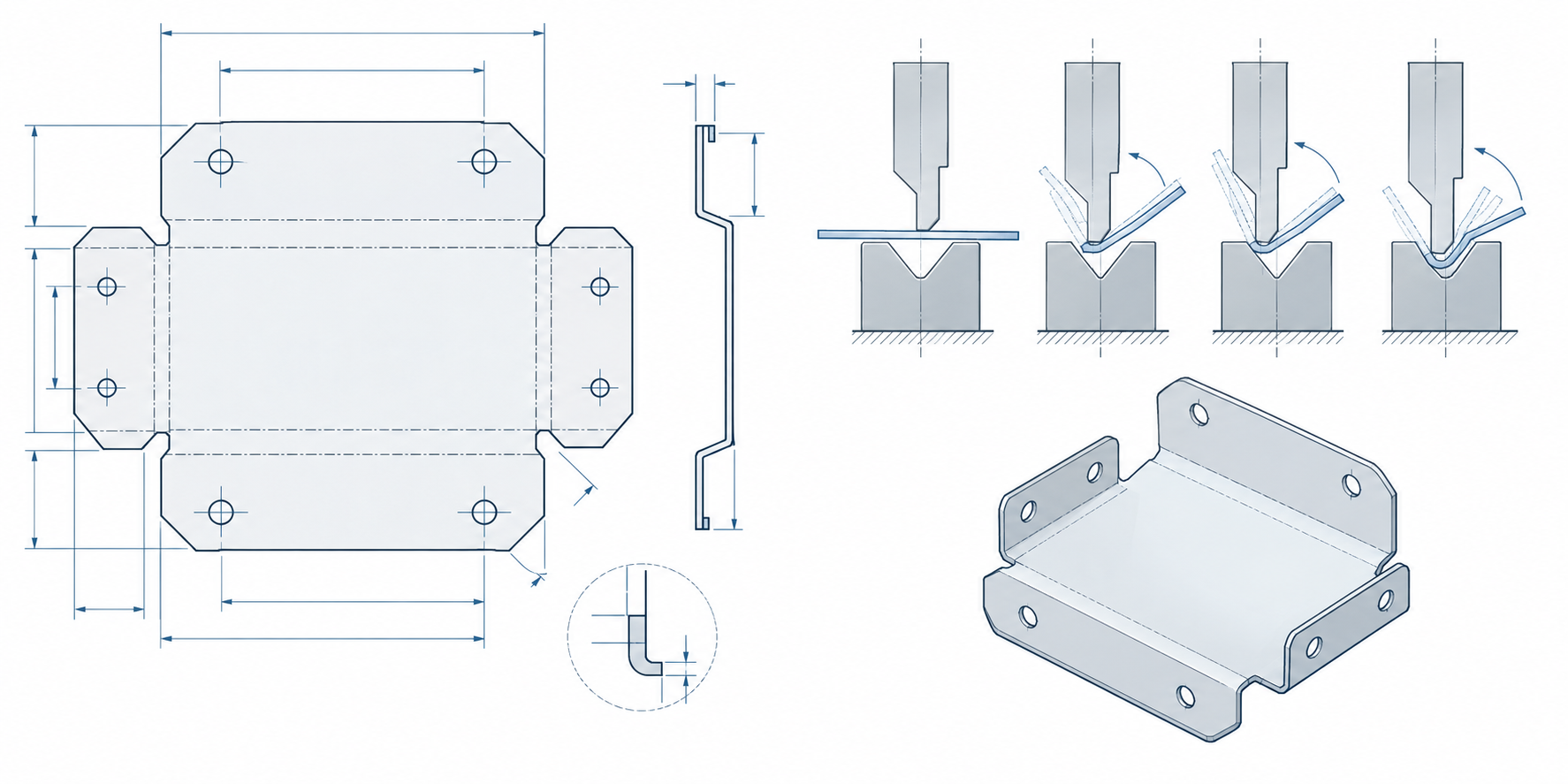
Parts such as enclosures, brackets, and mounting plates follow the sheet metal path, and the focus of the prototype is completely different from machined parts. CNC prototypes focus on mating surfaces and hole-position accuracy, while sheet metal prototypes focus on bend development, bending sequence, and assembly datums—if the flat pattern is calculated wrong, the bent part will not assemble, and the problem is often not in the machining but in the drawing itself.
Before prototyping, engineers are advised to first confirm the flat pattern, bending sequence, and datum holes, especially where multiple bends interfere with one another. Welded parts must also consider the effect of welding deformation on hole positions, and whether subsequent surface treatment (painting, anodizing, brushing) will change assembly clearances. These factors can be exposed at the single-piece prototype stage, which is far more cost-effective than changing them after mass production.
Procurement should also ask: will subsequent small batches use the same process. If the prototype is laser cutting plus bending, but mass production is planned to use a stamping die, then the prototype’s hole positions and edge condition can only serve as an assembly verification reference and cannot be directly used as the acceptance baseline for mass-produced parts. For sheet metal capabilities and process boundaries, refer to the sheet metal fabrication capabilities page; specific flat-pattern and bending plans should be confirmed with engineering.
Clarify these points before requesting a quote to save a round
Going back and forth several times on a prototype quote is usually not because the supplier calculates slowly, but because the requirements themselves are not aligned. State the following items clearly at the time of inquiry, and you can usually save a round of clarification.
- Purpose: assembly verification, appearance review, or small-batch trial production directly determines the process direction.
- Intended material: whether it must be close to the final material, or whether shape verification is the main goal.
- Critical dimensions and appearance surfaces: which mating surfaces, hole positions, and threads must be guaranteed, and which surfaces are appearance surfaces.
- Quantity and subsequent connection: one piece, a few pieces, or dozens of pieces, and whether it will later transition to injection molding or small-batch sheet metal.
Beyond the drawing, it is best to add a sentence about “what this part is most afraid of going wrong,” so the engineering side can judge the process trade-offs accordingly. If the material is uncertain, refer to the materials library first before communicating.
Frequently Asked Questions (FAQ)
The following questions appear most frequently in prototype review meetings, and the answers depend on the purpose rather than the process itself.
Must a prototype use the final mass-production material?
Not necessarily. If the goal is assembly verification and structural interference checking, alternative materials that are easy to machine or easy to print can be used for rapid iteration; if appearance review, heat resistance, or chemical compatibility is involved, it is recommended to stay as close to the final material as possible, and the key performance items should first be confirmed with engineering.
Should appearance parts use 3D printing or vacuum casting?
For a single piece or a small quantity with complex geometry, 3D printing iterates faster; when multiple parts with consistent appearance texture and color are needed, prototype vacuum casting is usually more suitable. Both can improve the surface through post-processing, and the final decision should be based on the review criteria.
Can CNC prototypes be delivered directly as small-batch production?
When the quantity is not large and the structure is suitable for cutting, CNC parts can be used directly for trial assembly or even small-batch use; however, if the next step is to move to injection molding, the structure and mold feasibility still need to be re-evaluated according to the mass production process.
Do sheet metal prototypes need tooling?
Most sheet metal prototypes are completed through laser cutting, bending, and welding, and usually do not require stamping dies; only when it is confirmed that mass production will use stamping and the volume is considerable does the mold investment need to be evaluated.
A quick-reference table: map the question to the process
| Questions the prototype needs to answer | Preferred process | What to focus on | Common pitfalls |
|---|---|---|---|
| Will it assemble, and do the fits match? | CNC machining | Hole positions, mating surfaces, threads, structural strength | Using printed parts to evaluate the assembly feel of injection-molded parts |
| Is the shape and structure reasonable, and is iteration fast? | 3D printing | Surface flow, interference, assembly space | Treating the surface condition of printed parts as the final appearance |
| Does the appearance look right, and are the color and texture correct? | Vacuum casting (prototype vacuum casting) | Appearance surfaces, parting lines, color matching, hardness/softness | Unit cost is relatively high when the quantity is too small |
| Small-batch trial assembly, market samples | Vacuum casting / small-batch CNC | Quantity, unit cost, and alignment with the mass production process | The prototype process and the mass production process are inconsistent, causing the acceptance baseline to be misaligned |
| Are bending, hole positions, and welding feasible? | Sheet metal prototyping | Bend development, bending sequence, datum holes, welding deformation | The flat pattern is calculated incorrectly, and the problem lies in the drawing rather than the machining |
Three common misjudgments, and how to avoid them in advance

Key takeaways
- First define the questions the prototype must answer: can it assemble, does it look right, can it be made in small batches—then choose the process.
- CNC suits dimensional and fit verification, 3D printing suits rapid iteration, and vacuum casting suits small batches of appearance parts.
- The prototyping logic for sheet metal parts is different, focusing on bend development, hole positions, and welding deformation.
- When the prototyping process is disconnected from the mass-production process, the prototype can only serve as a reference for assembly and shape, not as a mass-production acceptance baseline.
- Before requesting a quote, clearly state the purpose, intended material, critical dimensions, appearance surfaces, and quantity to significantly reduce back-and-forth communication.



