
Precision is not a machine tool parameter, but the accumulation of errors over time
A common scene on the shop floor: a machining center with a high nominal positioning accuracy, with no changes to the program, tool, or material, yet the semiconductor parts it produces are out of tolerance on critical dimensions. The operator's first reaction is to suspect the machine, so they re-set the tool, re-align, or even switch to another machine—but the problem persists. The real cause is often not the machine's static parameters, but that errors accumulate little by little within the machining cycle.
Semiconductor parts usually share common characteristics: not large in size, but with concentrated form and position requirements; materials are mostly stainless steel, aluminum alloy, engineering plastics, or special alloys; structurally, they often have thin walls, deep cavities, slender holes, or high length-to-diameter ratio features. Such parts are more sensitive to "stability" than to "peak precision." The roundness and straightness measured on a machine in a cold state may be completely different from its performance after four hours of continuous machining.
Breaking down the errors, they roughly come from four directions: heat—the environment, spindle, ball screw, and cutting heat continuously change the relative position between tool and workpiece; force—cutting force causes thin walls to deflect and residual stress to redistribute; vibration—chatter and spindle dynamic characteristics affect surface and dimensional consistency; measurement—if the measurement datum, temperature compensation, and probe compensation are not aligned, "qualified" may be an illusion. These four types of errors do not exist independently; they amplify each other within the same machining time.
Therefore, this article does not follow the conventional order of "machine—tool—fixture," but is organized according to the path of error accumulation over time: first heat, then force and vibration, then datum transfer in fixturing, and finally back to measurement and process control. The goal is not to give a universal parameter, but to provide a set of judgment logic usable on the shop floor—when a part is out of tolerance, knowing which link to check first, how to verify, and which mitigation measures are worth investing in.

Heat: The Underestimated First Source of Deviation
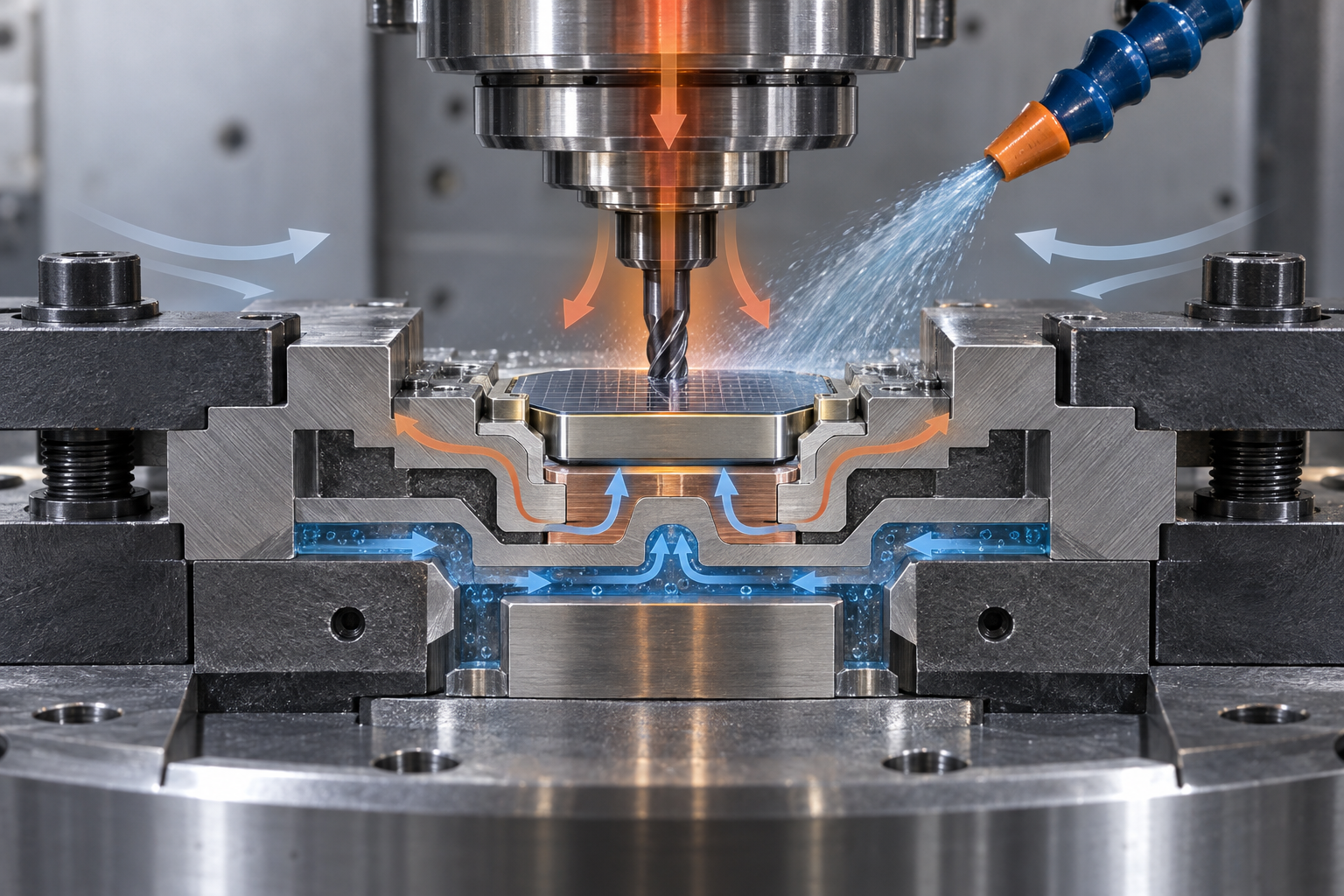
Semiconductor parts often have very little margin left in the dimensional chain, and thermal deformation is the only type of error where "the machine does not move, but the part does." It is not reflected in the machine's static geometric accuracy, yet it continuously changes the relative position between tool and workpiece within the machining cycle. To understand heat, one must first acknowledge that it is not a single source, but several paths acting simultaneously.
Four Thermal Paths: From Environment to Workpiece
- Ambient temperature fluctuation: day-night temperature differences in the workshop or air conditioning startup/shutdown cause the bed, workpiece, and measuring instruments to slowly expand and contract together. The larger the part and the higher the material's expansion coefficient, the more pronounced this drift.
- Thermal elongation of spindle and ball screw: during continuous machining, the spindle and ball screw heat up, and the axial position changes accordingly. This manifests as inconsistency between "the first part after startup" and "the part after running for two hours."
- Cutting heat entering the workpiece: especially with materials with poor thermal conductivity such as stainless steel and titanium alloy, heat concentrates in the cutting zone, thin-walled parts expand locally, and then contract back after cooling.
- Inconsistent coolant temperature: coolant is both a chip evacuation medium and a heat carrier. When the liquid temperature is unstable, it instead carries heat unevenly to the workpiece and bed.
The way these four paths superimpose determines that: looking at any single one alone often fails to find the root cause. A more practical approach on the shop floor is to measure along the time dimension, rather than measuring a single part.
Two Zero-Cost Judgment Methods
First, compare the first and last parts in continuous machining. With the same program and same fixturing, run several parts continuously and measure only the critical dimensions. If the dimensions drift in one direction, heat is the main suspect; if the dimensions jump randomly, it is more likely vibration, fixturing, or tool wear. Second, re-measure after stopping. Leave the just-unloaded part in a constant-temperature environment for a period before measuring; if the dimensions clearly spring back, it indicates that cutting heat or fixturing stress is at work, rather than inaccurate machine positioning.
Mitigation Approach: Let Heat Stabilize First
The direction is not to "eliminate heat," but to let heat reach steady state before cutting critical dimensions. Common practices include: letting the machine run idle or warm up to thermal equilibrium before critical operations; scheduling finishing after roughing, during a period when temperature is relatively stable; using symmetrical material removal for thin-walled parts to avoid one-sided accumulation of heat and stress; keeping coolant temperature as stable as possible, using independent temperature control when necessary. These measures do not change the machine's nominal accuracy, but they can significantly compress the amount of drift within the machining cycle. Specific parameters need to be confirmed together with the engineering team based on part material, structure, and equipment condition.
Vibration and Cutting Force: The True Opponents of Thin-Wall and Deep-Cavity Structures
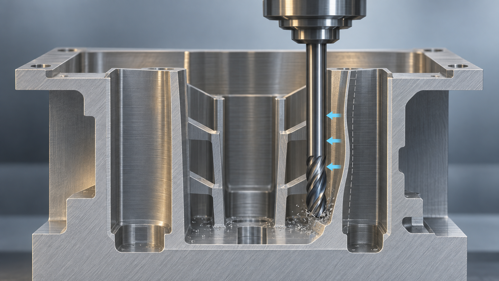
Many parts in semiconductor equipment look simple in appearance but are actually difficult due to thin walls, deep cavities, and high length-to-diameter ratios. For example, a cold plate with dense flow channels, a cavity cover plate with very thin walls, or a slender transmission shaft. Such structures have almost no rigidity against cutting force; as soon as the tool makes contact, the workpiece deflects first, then the tool cuts, and the dimension drifts. Thermal deformation is a slow variable, while vibration and cutting force are fast variables occurring with every tooth engagement—the handling logic for the two is completely different.
Chatter, Tool Deflection, and Residual Stress: Three Different Types of Drift
Dimensional drift encountered on the shop floor usually comes from three mechanisms, but their manifestations are easily confused. Chatter is self-excited vibration between tool and workpiece, leaving regular chatter marks on the surface, with dimensions often fluctuating within a certain range; tool deflection is cutting force pushing the thin wall away, so the tool actually cuts less than the program specifies, resulting in oversized wall thickness and undersized slot width; residual stress release is more insidious—material removal breaks the original stress balance inside the blank, and the part may slowly bend after machining or even after being left for a period. The judgment method is straightforward: if, with the same program and same tool, dimensional deviation increases as the wall becomes thinner, it is most likely tool deflection; if the surface has periodic patterns accompanied by abnormal noise, suspect chatter first; if the first part is qualified but goes out of tolerance after being left or after subsequent stress relief, check residual stress.
Tool Overhang and Feed Strategy: Reduce Force First, Then Talk About Speed
To deal with thin walls and deep cavities, the first principle is to reduce radial cutting force, rather than simply increasing spindle speed. The longer the tool overhang, the more pronounced the rigidity drop, so keep it as short as possible, and when necessary use a thicker tool holder or a dedicated extension rod to regain rigidity. For feed, small depth of cut with large feed per tooth is often more stable than large depth of cut with small feed, because the former distributes force along the axial direction and reduces deflection. Deep cavity machining can use layered material removal to release allowance evenly, avoiding a sudden full-width cut in one pass. For slender features with high length-to-diameter ratios, roughing first then finishing, with symmetrical material removal, is more controllable than cutting to full depth in one pass. Cooling and chip evacuation must also be considered simultaneously; chip accumulation will cause secondary scratching of the machined surface.
Support Methods: "Borrowing Back" Workpiece Rigidity
When the part itself lacks sufficient rigidity, support must compensate. Common practices include leaving process ribs or process bosses in the cavity and removing them after machining; using removable filler material to temporarily support thin walls; or adjusting the process sequence to machine the rigid portions first and release the thin-wall areas last. These methods all add operations, but compared with out-of-tolerance rework, they are usually more cost-effective. Which one to choose depends on whether the part ultimately allows support marks to remain, and whether there is subsequent deburring and cleaning capability. For such structures, it is recommended to send the drawing and key features to engineering for evaluation before quoting, confirm the support plan and inspection method, and then decide whether to use CNC or do prototype verification first.
Workholding: the most error-prone link in datum transfer
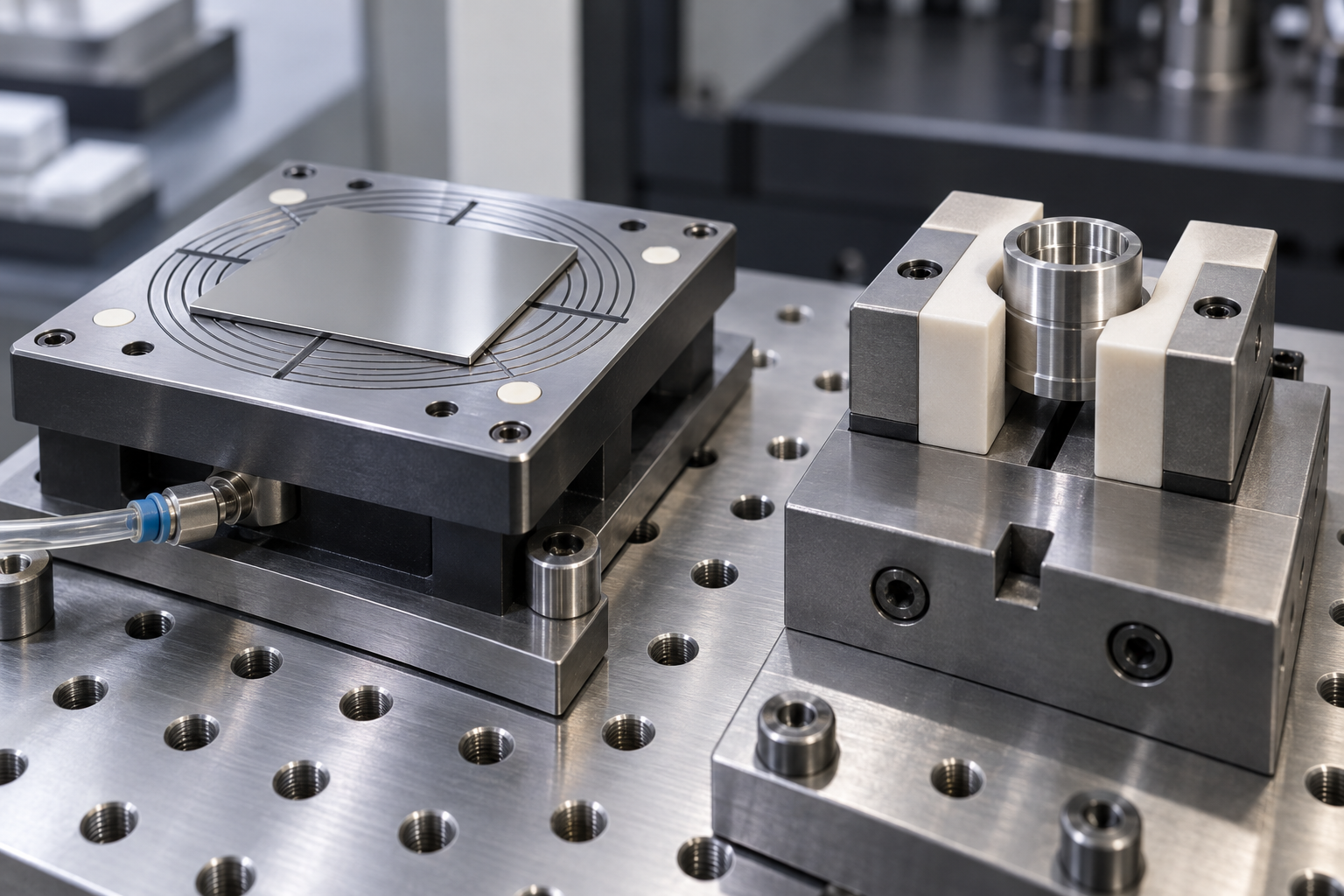
There is a typical class of structures in semiconductor parts: not large in overall shape, but with several holes, slots, or sealing surfaces that have very tight positional tolerance requirements, and often only one or two faces can be used for locating. Precision problems with this type of part are rarely because the machine tool "can't cut it"; more often, the datum relationships are lost at the workholding stage. Clamping force causes elastic deformation of the workpiece, which springs back after the jaws are released; multiple setups then accumulate locating errors layer by layer into the final dimensions.
Elastic deformation caused by clamping force
Thin-walled or cantilevered structures are pressed down during clamping, and during cutting the tool "sees" a constrained shape; after release, the workpiece springs back, and dimensions and flatness change. The method of judgment is straightforward: measure key dimensions in the clamped state, then measure again after release; the difference between the two is the deformation introduced by workholding. Mitigation approaches usually include reducing clamping force, adding support points, moving clamping positions to regions with better rigidity, or switching to surface contact rather than point contact clamping.
Datum unification and fixture selection
There is only one principle: the machining datum should equal the measurement datum as much as possible. If the first operation locates on a raw stock surface and subsequent operations switch to locating on a machined surface, the datum has changed, and errors will accumulate. Vacuum chucks are suitable for large-area, thin-plate parts; clamping force is uniform but suction is limited. Soft jaws are suitable for parts with a machined outer diameter or regular profile; they reduce clamping marks, but repeat locating depends on chuck accuracy. Dedicated fixtures are suitable for parts with stable batch production and fixed structure; upfront investment is high, but the datum can be fixed. Which to choose depends on part rigidity, batch size, and subsequent measurement method; it is recommended to confirm with engineering during the prototyping stage.
Measurement: if the measurement method is wrong, conformance is only an illusion
There is a recurring scenario in semiconductor parts: a CMM report shows dimensions within the drawing tolerance, but the part cannot be assembled into the station, or after assembly the function drifts. The problem is often not in machining but in the measurement step—the measurement method itself introduces deviation, or the measurement state is inconsistent with the assembly state. If measurement is treated as "the final confirmation" rather than "part of machining," conformance is only conformance on paper.
What CMM, vision measurement, and 3D scanning each handle
Contact CMM measurement is suitable for regular geometry, deep holes, steps, and dimensions requiring strict datum alignment; probe radius compensation and measurement point distribution directly affect the result. Vision measurement is friendly to thin-wall contours, small features, and edge projection, but has weaker constraints in the height direction and on datum-free freeform surfaces. 3D scanning excels at overall shape, freeform surfaces, and reverse comparison, and can quickly provide a full-field deviation color map, but its value depends on the datum alignment method and surface preparation before scanning. The three are not substitutes for one another; they cover different feature types.
Temperature compensation is often overlooked. After the workpiece is removed from the machine tool, its temperature is still changing; if measured immediately, readings will drift as the workpiece cools. A safer approach is to let the workpiece reach thermal equilibrium in the measurement environment before measuring, and to record the environmental conditions at the time of measurement in the report. Probe radius compensation, probe calibration, and datum alignment are also sources of error: if the datum is chosen incorrectly, all subsequent dimensions will shift or rotate as a whole.

When the part is a freeform surface, thin-walled, or needs full-field comparison with the original CAD model, the role of 3D scanning is very clear: it expands "point dimensions" into "surface deviation," helping to judge deformation trends and assembly interference regions. This type of inspection is more sensitive to datum establishment and scanning parameters; it is recommended to confirm the comparison datum together with the machining party, rather than relying only on a color deviation map. If you need reverse engineering or inspection scanning support, you can learn about the applicable scope through 3D scanning capabilities, or directly submit drawings and inspection requirements together via AI chat quote.
Build precision into the process: control points from prototyping to small-batch production
The previous sections discussed where errors come from. This section takes a different angle: precision is not "tuned" through a single operation, but "locked in" through the process. On the same machine tool with the same program, why is the first part conforming but the thirtieth part starts to drift? Often it is not that the machine tool suddenly gets worse, but that the process is missing several control points that block errors from propagating.
First article confirmation and in-process sampling: define "conformance" clearly
First article confirmation is not just measuring one dimension. It must answer three things: whether the datum is consistent with the drawing, whether key features are within the expected range, and whether the machining process has reached thermal equilibrium. If the first article is made right after the machine is turned on, it may only be "cold-state conforming" and does not represent the stable state. A safer approach is to let the machine run a warm-up or air-cutting period first, confirm the first article after the state stabilizes, and use the first article data as a reference for subsequent sampling.
The frequency of in-process sampling depends on the criticality of the part and the machining duration. For dimension-sensitive scenarios such as semiconductor parts, sampling is usually performed at fixed intervals during continuous machining, rather than measuring everything together after all processing is complete. Once a trend shift is found, adjustments can be made before batch scrap occurs.
Thermal equilibrium waiting and tool life: two waits that are easily skipped
Thermal equilibrium waiting sounds like a waste of time, but it is often cheaper than rework. During continuous machining, the temperature of the spindle, ball screw, and workpiece rises slowly, and dimensions drift accordingly. If the process allows, leaving cooling or stabilization time between roughing and finishing before entering finishing is often more stable than doing it all in one go. The same applies to tool life: as the same tool is used toward the later stage, cutting force and tool deflection change; finishing of critical dimensions is best arranged when the tool is in good condition, or tool change points should be established.
Traceable records: let problems be reviewed
Records are not a formality. Program version, tool number, workholding method, measurement data, and environmental conditions—these pieces of information are the only clues that can trace the source of errors when batch differences occur. Without records, you can only guess; with records, you can determine whether it is heat, workholding, or tool wear.
Prototyping stage: CNC, 3D printing, and handboard vacuum casting each cover a segment
In the validation stage of semiconductor parts, the roles of the three processes do not overlap. CNC machining is suitable for validating dimensions and assembly under real materials, especially scenarios requiring metal or engineering plastic load-bearing, sealing, and fitting. 3D printing is more suitable for quickly validating shape, flow channels, and assembly interference, with fast iteration speed, but the material is often different from the final part and cannot be directly equated with production performance. Handboard vacuum casting is suitable for functional or appearance validation in the small-batch stage using resin parts close to the final material, positioned between prototype and production.
The timing of switching processes usually depends on the validation goal: if validating "can it fit in," 3D printing may be enough; if validating "are dimensions stable under real operating conditions," CNC or cast parts are needed. Aligning validation goals with process capabilities saves more time than blindly pursuing "the most production-like."
Common questions: several precision questions most often asked on the shop floor
When a semiconductor part is out of tolerance, should the machine tool be checked first or heat and workholding first?
Rule out heat and workholding first, then suspect the machine tool. The static geometric accuracy of a machine tool is relatively stable, while thermal drift and workholding deformation change over time and between batches. A practical order is: first compare the first and last parts of continuous machining to determine whether there is one-way drift; then measure key dimensions once each in the clamped and released states to quantify the deformation introduced by workholding; after both are ruled out, return to machine tool geometric accuracy, spindle dynamic characteristics, and tool condition. This avoids blindly changing equipment or repeatedly setting tools.
During thin-wall machining, the wall thickness is always too large and the slot width too small. What is the cause?
This is a typical tool deflection phenomenon: cutting force pushes the thin wall away, and the actual material removed by the tool is less than the programmed value, so the wall thickness is too large and the slot width too small. The mitigation direction is to reduce radial cutting force, not to increase spindle speed. Try shortening tool overhang, using a small depth of cut with a large feed per tooth, adding process ribs inside the cavity or temporary filling support, and arranging finishing after stress relief. If regular chatter marks also appear on the surface, consider chatter as well and check spindle dynamic characteristics and tool clamping rigidity.
The CMM measurement passes, but the part cannot be assembled. Where is the problem?
Most likely the measurement state is inconsistent with the assembly state. Common causes include: the measurement datum and machining datum are not unified, masking positional tolerance; the workpiece is measured before reaching thermal equilibrium after coming off the machine, so readings drift as it cools; there is deviation in probe radius compensation or probe calibration; and only point dimensions are measured without evaluating overall shape and deformation trends. It is recommended to let the workpiece stabilize in the measurement environment before measuring, record the environmental conditions in the report, and supplement freeform or thin-walled parts with 3D scanning for full-field comparison.
In the small-batch prototyping stage, to what extent should precision control be carried out?
The value of the prototyping stage lies not in a single qualified part, but in clearly defining the datum, fixturing, and inspection scheme together. It is recommended to confirm at the first-article stage: whether the machining datum equals the measurement datum, whether the clamping force will cause measurable deformation, which measurement method to use for critical dimensions, and how long thermal stabilization requires. Once this information is locked in, fluctuations in the mass production stage will be significantly reduced. If prototyping only pursues dimensional pass without regard for process consistency, rework is often required during mass production.
What level of workshop temperature control is considered sufficient?
There is no universal value; it depends on part size, material expansion coefficient, and tolerance band. The principle is: keep dimensional changes caused by ambient temperature fluctuations below a reasonable proportion of the tolerance band. Rather than pursuing an extremely low absolute temperature, temperature stability is more important—avoid periodic drift caused by air conditioning cycling on and off, frequent door openings, or day-night temperature differences. For precision-sensitive operations, allow the machine tool to warm up to thermal equilibrium before cutting critical dimensions, and schedule finishing as much as possible during periods of relatively stable temperature.
Key takeaways
- Precision is the result of four types of errors—thermal, force, vibration, and measurement—accumulating over time; looking at any single one alone often fails to find the root cause.
- Thin walls, deep cavities, and high length-to-diameter ratio structures make fixturing force and cutting force the main sources of deviation; reducing force is more effective than increasing speed.
- Temperature stability is more important than pursuing extreme machine tool parameters; comparing the first and last parts in continuous machining can quickly identify thermal drift.
- If the measurement datum is inconsistent with the machining datum, real deviations will be masked as "qualified."
- The datum, fixturing, and inspection plan should be defined together at the prototyping stage, rather than remedied after out-of-tolerance occurs.



