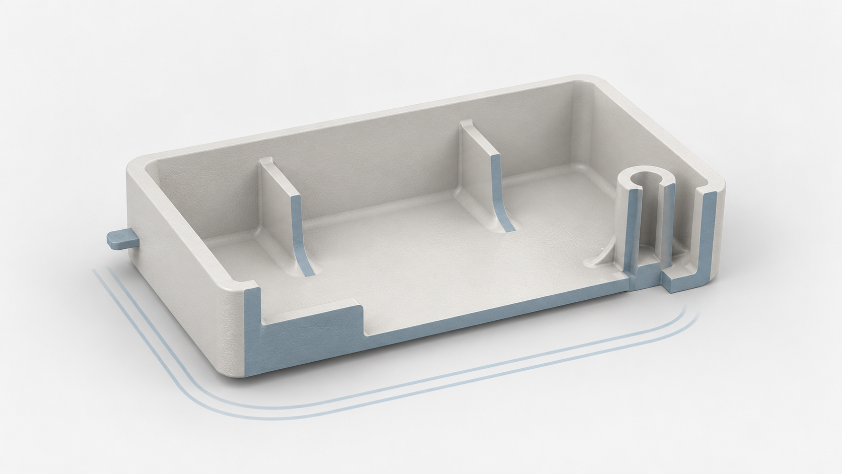
Why Injection-Molded Parts Develop Sink, Sink Marks, and Warpage: From Local Thick Sections to Uneven Cooling
After a trial run of an engineering plastic enclosure, sink marks appeared on the cosmetic surface, the flatness of the assembly surface was out of tolerance, and the bracket interfered with its mating component. The shop floor often first tries increasing packing pressure, but this is not necessarily effective. If the root cause is uneven wall thickness, material buildup at rib roots, thick sections at the bases of bosses, or unbalanced mold cooling, simply adjusting injection molding parameters can only change how the defect appears; it cannot eliminate differences in shrinkage.
Shrinkage in Injection-Molded Engineering Plastic Parts Usually Starts in Thick Sections
After the plastic melt fills the cavity, it gradually cools and shrinks. Thicker sections dissipate heat more slowly, and packing pressure may also be difficult to transmit continuously to distant areas, making volumetric shrinkage more pronounced after cooling. The areas behind cosmetic surfaces—ribs, screw bosses, rib intersections, and connections with sudden increases in thickness—are key inspection zones for sink marks. Making the main wall thicker may increase material consumption, cooling time, and local shrinkage. Properly reducing the thickness of ribs and bosses, using hollow structures, or applying gradual transitions is generally more effective for controlling thick sections.
Warpage in Injection-Molded Parts Results from Differential Shrinkage, Not Just Machine Parameters
When cooling rates, material orientation, or shrinkage vary across different regions of a part, internal residual stresses may be released after demolding, causing bending, twisting, or deformation of assembly surfaces. Glass-fiber-reinforced engineering plastics may also exhibit anisotropy along the flow direction. The troubleshooting sequence should be standardized: first examine the geometry and local thick sections, then verify the material grade and shrinkage data; next check the gate location, cooling layout, and packing-pressure window; finally confirm the measurement datums for flatness and critical dimensions, as well as the actual assembly requirements. Mold flow analysis can help compare options, but validation with trial parts and dimensional inspection is still required.

How to Determine Wall Thickness for Injection-Molded Engineering Plastic Parts: Balancing Uniformity, Flow Length, and Functional Strength
Wall thickness is the first structural consideration in the DFM of injection-molded engineering plastic parts. For some thermoplastic injection-molded parts, approximately 1.2–3 mm can serve as an initial review range, but this is not a universal limit. The resin grade, flow length, part size, filling pressure, and functional loads all affect the appropriate value. During drawing review, first identify the nominal wall thickness T, then separately check abrupt thickness transitions, long flow paths, and critical assembly surfaces.
| Design Observation Points | Empirical Starting Point | Risks Requiring Confirmation |
|---|---|---|
| Nominal Wall Thickness | For some thermoplastic parts, an initial reference range of approximately 1.2–3 mm may be used | Material flowability, flow length, short shots, and filling pressure |
| Thickness Transition | Use gradual transitions wherever possible rather than pursuing absolute uniformity in all areas | Slow cooling in thick sections, increased material usage, and sink marks |
| Functional Thickening | Prioritize hollowing, localized support, or reinforcing ribs | Localized thick sections form at rib roots, boss bases, and intersections |
Injection-molded wall thickness design should control shrinkage differences rather than pursue complete uniformity
Thick-wall areas typically cool more slowly, and the effectiveness of holding pressure may also decrease as flow distance and the frozen layer change, ultimately resulting in sink marks, dimensional deviations, or localized deformation. Thin walls and long flow paths, on the other hand, may increase filling pressure and raise the risk of short shots, weld lines, or uneven filling. Therefore, “uniform wall thickness” should be understood as balancing material mass distribution and cooling conditions as much as possible, rather than using the same thickness in every functional area. Locations that must bear loads can achieve strength through rear-side support, hollow structures, and gradual transitions instead of simply making the entire surface thicker.
Engineering Plastic Injection-Molded Part Drawings Should Record T, Datums, and Assembly Requirements
In the DFM documentation, specify T, the locations of local thick sections, the thickness transition method, and the material grade, while distinguishing cosmetic surfaces, sealing surfaces, sliding surfaces, and critical assembly surfaces. If a particular area must be thickened, also specify the permitted sink-mark locations, dimensional datums, and flatness or clearance requirements. This enables the supplier to evaluate the wall-thickness design together with the gate, cooling, and inspection methods, rather than relying on increased holding pressure as a corrective measure only after mold trials.

How to Design Reinforcing Ribs and Bosses to Increase Rigidity Without Creating Sink Marks
| Reinforcing Rib Thickness | Approximately 0.5–0.6T; some designs may allow approximately 0.75T | Sink marks at rib roots, uneven cooling, and deformation of cosmetic surfaces |
| Rib height | Can initially be checked at approximately 2.5T | Excessive height can alter filling, demolding, and stiffness benefits |
| Boss wall thickness | Can initially be checked as no more than approximately 60% of the main wall thickness | Thick sections at the boss base, sink marks, and ejection deformation |
Balancing stiffness and sink marks in ribs of injection-molded engineering plastic parts
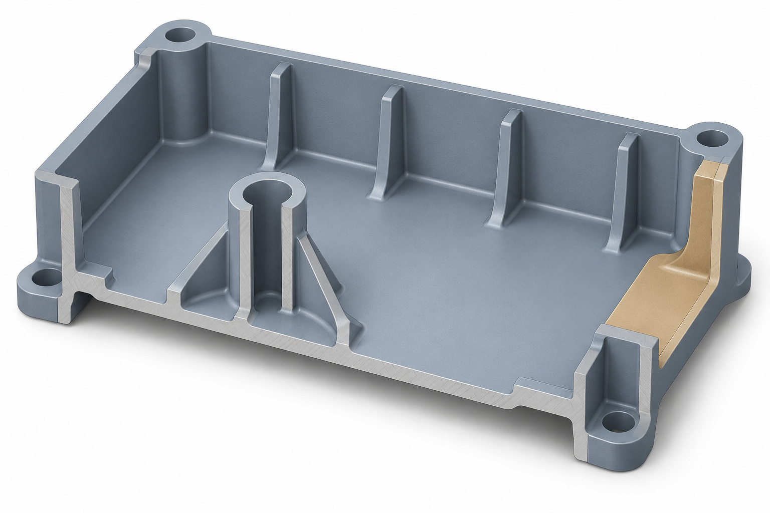
Draft angles, fillets, and parting lines: In injection molding DFM, solve demolding first, then address appearance and dimensions
Engineering plastic injection-molded parts shrink during cooling, and the inner walls may grip the core. If the draft angle is insufficient, ejection force will increase, making drag marks, whitening, or ejector-pin marks likely to appear on the surface. In severe cases, this can also increase the risk of damage to the core and mold. Therefore, draft angles should be determined during the injection molding DFM stage rather than remedied just before mold opening.
For general untextured sidewalls, approximately 0.5°–2° can be used as an empirical starting point for initial checks; deep cavities, enclosed surfaces, materials with more pronounced shrinkage, or textured surfaces may require approximately 3°–5°. The final value must be confirmed based on the draft direction, texture depth, material, appearance requirements, and mold structure. Increasing the draft angle generally helps reduce demolding force, but it may also affect appearance boundaries, assembly clearances, or effective dimensions, so it should not be increased arbitrarily without considering the part's function.
How to control wall-thickness transitions with fillets in injection molding DFM
Fillets are used not only to improve appearance, but also to reduce stress concentration at sharp corners, help the melt change direction, and reduce localized material accumulation caused by abrupt wall-thickness changes. As an initial check, internal fillets can be based on a value of approximately 0.5T or greater, where T is the adjacent nominal wall thickness; this is only an empirical starting value and still must be confirmed based on wall thickness, flow, mold machining, and load requirements. The roots of ribs, the bases of bosses, and the corners of inner and outer housings should be reviewed carefully to avoid filling and stress risks caused by fillets that are too small, while also avoiding the creation of new thick sections through fillets that are too large.
Parting lines, ejection locations, and cosmetic surfaces of injection-molded parts should be reviewed together
Parting lines should be kept away from primary cosmetic surfaces, sealing surfaces, and critical assembly surfaces whenever possible. Ejector pins should be positioned in areas with sufficient rigidity that can withstand ejection forces. During design reviews, confirm the demolding direction, the need for slides or lifters, acceptable areas for ejector-pin marks, and whether the texture direction will alter the draft requirements. If the housing exhibits snap-fit interference or assembly sticking, first check the draft, parting, and ejection references before deciding whether process parameters need to be adjusted.
How gate, runner, and cooling layouts affect shrinkage and warpage in injection molding
In injection-molded engineering plastic parts, the gate is not merely a mold detail; it is a DFM decision that affects the filling path, the effectiveness of holding pressure, material orientation, and shrinkage distribution. Positioning the gate near a thick section may improve compensation for shrinkage in that area, but it may also increase material accumulation, appearance defects, or residual stress near the gate. If the gate is positioned away from the thick section, the pressure loss and sink-mark risk at the end of the long flow path must be checked. The gate location should also avoid critical load-bearing surfaces, assembly surfaces, and prominent cosmetic surfaces, and gate vestige and the removal method should be confirmed in advance.
Compare the filling paths first in injection molding DFM, then determine the gate location
Multi-gate concepts should not be evaluated solely by whether the part is filled. The balance of the flow fronts, whether weld lines fall in weak areas, and whether the orientation of glass fibers in reinforced materials will amplify dimensional differences must also be considered. For the same part, different gate concepts can be compared for filling, packing, and shrinkage trends, but mold-flow results still need to be validated through trial molded parts, critical dimensions, and actual assembly.
Unbalanced cooling amplifies injection molding warpage
Thick sections, rib roots, the bottoms of bosses, and rib intersections cool more slowly. If cooling conditions are inconsistent between the core, cavity, or different regions, the two sides of the part will shrink at different rates, ultimately resulting in warpage, out-of-tolerance flatness, or assembly interference. Troubleshooting should proceed in the following order:
- First check the wall thickness, local thick sections, and abrupt thickness transitions to confirm whether the issue is caused by the geometric distribution of material.
- Then verify the material grade, reinforcement ratio, and supplier shrinkage data. Do not use a uniform compensation value that is detached from the material conditions.
- Next compare the gate, runner, cooling circuits, and packing window, focusing on filling balance, cooling temperature differences, and the compensation flow path.
- Finally, define the inspection datum, flatness measurement method, and assembly conditions to avoid judging warpage against inconsistent datums.
Amorphous and semicrystalline, reinforced and unreinforced materials: how material differences enter injection molding DFM
Material selection for engineering plastic injection molded parts cannot be based solely on strength, temperature resistance, or cost. Amorphous and semicrystalline materials may differ in shrinkage behavior, dimensional stability, chemical resistance, and melt-flow performance. Even when changing the resin grade within the same material class, the gate direction, packing window, and critical tolerances may need to be reevaluated. Injection molding DFM should treat the material as part of the structure and process, rather than as procurement information to be confirmed after the mold is built.
Material data for engineering plastic injection molded parts cannot be replaced by a uniform shrinkage rate
Shrinkage is jointly affected by the resin grade, molding direction, filler ratio, gate location, packing, and cooling conditions. Without the specific grade, reinforcement ratio, and supplier data, a single shrinkage compensation value should not be applied directly. At a minimum, the DFM record should include the material grade, unreinforced or reinforced status, glass-fiber ratio, recommended molding window, and the source and applicable direction of the shrinkage data.
Glass-fiber orientation and anisotropy must be checked in reinforced engineering plastic injection molded parts
Glass-fiber-reinforced materials generally improve stiffness and dimensional stability, but the fibers orient along the flow direction, causing differences in shrinkage and stiffness in different directions. If the gate is positioned improperly, the cosmetic surface, long edges, or assembly datums may exhibit deformation, texture variation, or dimensional shift. Therefore, after a material change or adjustment to the reinforcement ratio, the gate direction, flow length, warpage trend, and critical assembly dimensions should be rechecked and confirmed through trial molded parts and actual inspection.

How mold-flow analysis, trial molding, and dimensional inspection validate injection molding warpage risk
Mold-flow analysis is suitable for ranking risks before mold construction; it is not a button that guarantees an injection molded part will have “zero warpage.” It can compare gate concepts, observe differences in filling, packing, and cooling, and identify areas where shrinkage may be concentrated. When using glass-fiber-reinforced engineering plastics, fiber orientation and the resulting anisotropy should also be considered. The analysis results should support design decisions: whether to adjust the wall thickness and local thick sections, or change the gate, cooling circuit, or ejection direction.
Injection molding warpage risk must be verified through trial molding and dimensional inspection
Trial molded parts must be measured against the drawing datums rather than judged by appearance alone. At a minimum, verify critical dimensions, flatness, hole locations, cosmetic surfaces, and actual assembly clearances. For housings or brackets, also confirm whether screw bosses, locating posts, and mating components experience interference. The measurement method, datums, environmental conditions, and part placement state affect the results and must be clearly documented in the inspection record. If the same location continues to shift across different molding batches, review the material, gate, cooling, and packing windows rather than simply increasing a single process parameter.
Turn Mold Flow and Injection-Molded Part Acceptance Requirements into Traceable Records
The DFM output should record the material grade and reinforcement ratio, critical dimensional tolerances, flatness or assembly clearances, inspection datums and measurement methods, and identify the areas where gate marks, ejector-pin marks, and allowable sink marks are permitted. When the material, gate location, mold cooling, or critical structure changes, reassess which analyses and dimensions require revalidation. Only in this way can “potential warpage” be converted into a verifiable engineering risk rather than remaining a verbal dispute after mold trials.
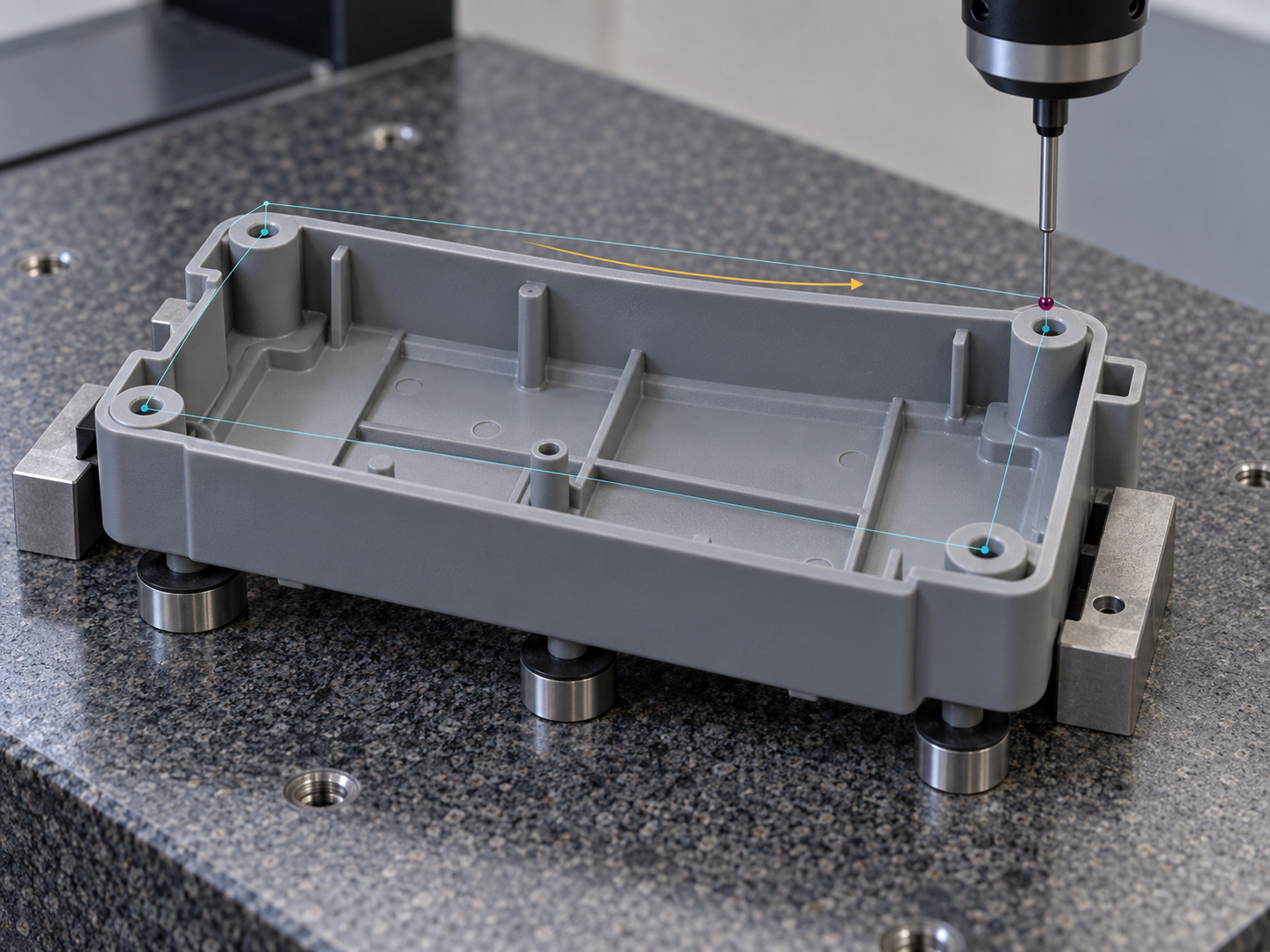
Pre-Mold-Fabrication DFM Checklist for Engineering-Plastic Injection-Molded Parts
The DFM conclusions for engineering-plastic injection-molded parts should not remain merely as verbal confirmations in meetings. Before mold fabrication, organize the material, structure, appearance, dimensional, and validation requirements into traceable records, and clearly identify which items have been confirmed and which still require review by the mold or material supplier.
Lock Down Material and Structural Data First
- Record the specific resin grade, reinforcement type, and ratio; after any material change, reassess shrinkage, warpage, flow direction, and critical tolerances.
- Mark the nominal wall thickness T, local thick sections, thick-to-thin transitions, ribs, and boss dimensions on the drawing or 3D model. Rib thickness, rib-root fillets, rib spacing, and the bottoms of bosses require particular attention; do not focus only on the average wall thickness.
- Confirm the draft direction, texture depth, parting line, and the need for slides or lifters, and identify permitted ejector-pin locations in advance. Insufficient draft may cause the part to grip the core, resulting in drag marks and ejection deformation.
- Specify the appearance surfaces, critical assembly surfaces, datums, dimensional tolerances, flatness or clearance requirements, and the acceptable areas for sink marks, weld lines, gate marks, and ejector-pin marks.
Include the Gate, Production Volume, and Validation Method in the DFM
The gate design should be confirmed in conjunction with the filling path, appearance requirements, load-bearing and assembly areas, and should specify the degating method and acceptable locations for any residual marks. RFQ materials should also include the target production volume, critical dimensional inspection methods, the flatness measurement datum, sample assembly conditions, and the allowable defect range. Mold flow analysis can be used to compare gate, packing, and cooling方案, but final acceptance must still be based on molded trial parts, dimensional inspection, and actual assembly validation.
Frequently Asked Questions
Shrinkage, warpage, and assembly deviations in engineering-plastic injection-molded parts typically require evaluation in combination with the structure, material, mold, and inspection conditions. The following questions address common decisions involving wall thickness, ribs, material orientation, and DFM validation.
Does a thicker wall always mean higher strength for an engineering-plastic injection-molded part?
Not necessarily. Increasing wall thickness may improve local load-bearing capacity, but it also increases material usage, cooling time, and shrinkage in thick sections, which can cause sink marks or warpage. In general, first use a uniform primary wall thickness, ribs, fillets, and adequate supports to achieve the required stiffness, then confirm the design based on the material grade, load, and assembly requirements.
Why can't the rib thickness simply equal the primary wall thickness?
When the rib thickness equals the primary wall thickness, the rib root can easily form a localized thick section that cools more slowly. Sink marks may appear on the appearance surface, and differences in shrinkage may amplify warpage. As an initial check, use approximately 0.5–0.6T of the adjacent primary wall thickness T; some designs may allow a larger value, but the rib root, intersections, fillets, and cooling layout must be revalidated.
Is warpage a design problem or an injection molding parameter problem?
Both are possible, but structural and material factors should be investigated first. Uneven wall thickness, material buildup at bosses or rib roots, gate location, shrinkage of semicrystalline materials, and glass-fiber orientation can all cause differences in shrinkage; the packing-pressure, cooling, and mold-temperature windows can also affect the results. During troubleshooting, examine the geometry and material first, followed by the gate, cooling, and process, and finally validate using dimensional measurements and assembly checks.
Why do glass-fiber-reinforced engineering plastics require greater attention to gate direction?
Glass fibers become oriented as the melt flows, which can cause shrinkage and stiffness to differ between the flow direction and the transverse direction. Gate location, flow paths, and multi-gate balancing can therefore affect warpage, critical dimensions, and appearance. The DFM documentation should record the specific grade and reinforcement percentage, and require the material or mold supplier to provide the corresponding shrinkage and orientation assessment.
Without mold-flow analysis, how can shrinkage and warpage risks be screened before mold opening?
First, mark the nominal wall thickness T, abrupt thickness transitions, rib roots, boss bases, intersecting ribs, cosmetic surfaces, and critical assembly surfaces on the 3D model and drawings; then confirm the material grade, gate direction, draft, and cooling feasibility. Record flatness, dimensional tolerances, permitted sink-mark areas, and the locations of gate and ejector-pin marks in the DFM documentation, and verify them through trial-molded parts, critical dimensions, and actual assembly checks.
Key takeaways
- Wall thickness design is the first line of control for preventing sink and warpage in injection molding, but the final range must be confirmed based on the material grade, flow length, and functional requirements.
- Ribs and bosses should improve stiffness through controlled thickness, fillets, spacing, and proper connections; simply increasing local thickness cannot replace sound structural design.
- Draft angles, gates, and cooling layouts should be determined before mold making. Otherwise, demolding force, flow orientation, and cooling imbalance may amplify dimensional risks.
- Mold flow analysis is suitable for comparing options and ranking risks, but it cannot replace mold trials, critical-dimension inspection, flatness inspection, and actual assembly validation.
- DFM and RFQ materials should clearly specify the material grade, cosmetic surfaces, critical datums, tolerances, acceptable gate and ejector-pin mark locations, and defect acceptance criteria.



