Ask about failure consequences first, then the process
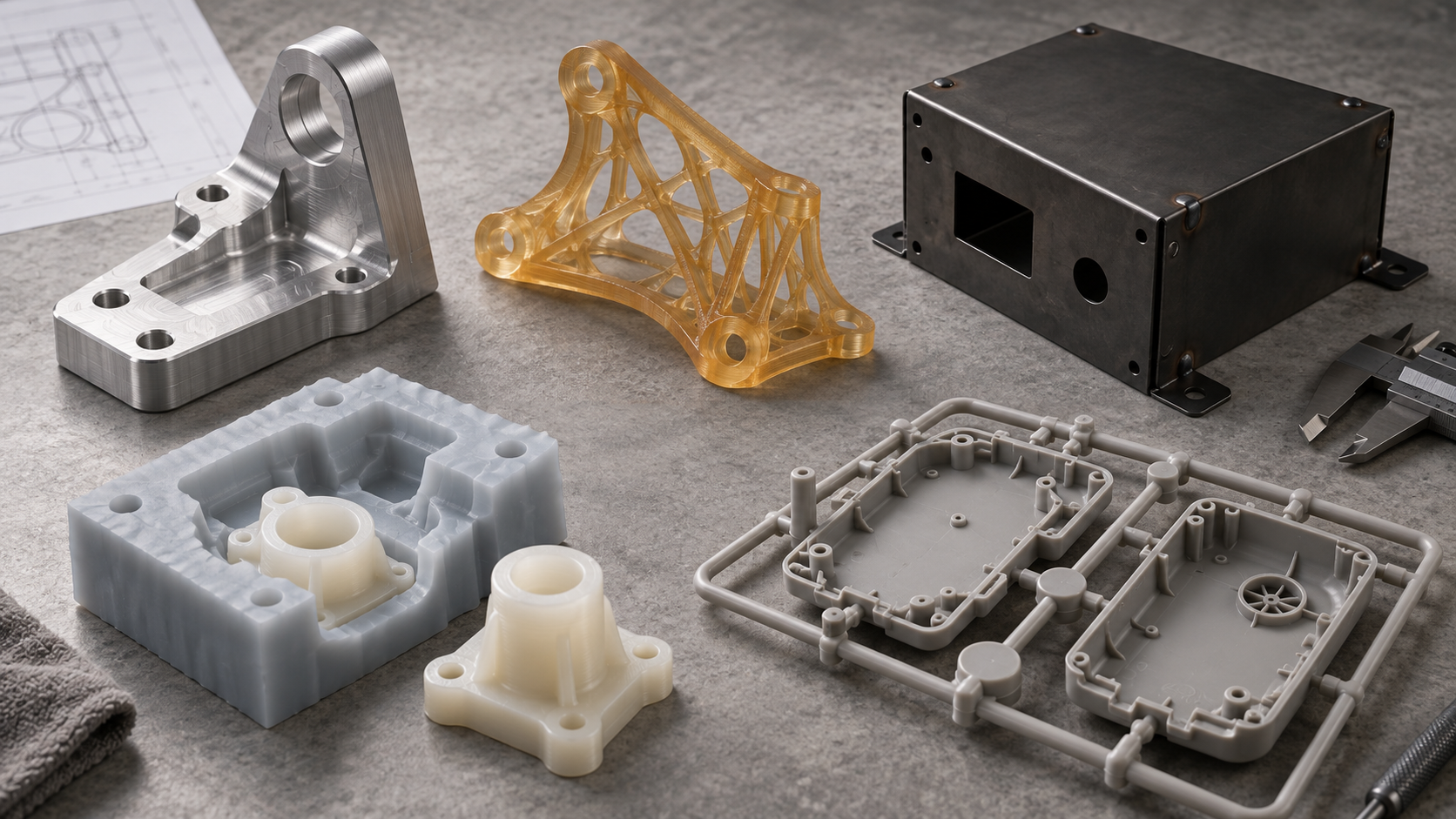
Send the same drawing to two suppliers, and the recommendations that come back may be completely opposite: one says, "This part is most reliable if directly CNC milled," while the other says, "Making a simple mold for prototype duplication is more cost-effective." Neither is necessarily wrong, but their default assumptions about failure consequences are different. The former assumes this is a load-bearing structural part, and if it breaks, the entire machine line stops; the latter assumes this is an appearance validation part that will be removed after a few photos are taken once installed. The first step in process judgment is not to flip through a process list, but to ask first: if this part breaks, what will happen?
Breaking this question down usually lands on four dimensions. First, where the functional surfaces are—mating surfaces, sealing surfaces, guide rail surfaces, gear meshing surfaces. The dimensions and surface quality of these locations directly determine function, and the process must prioritize ensuring them rather than applying uniform effort to the entire part. Second, the nature of the load—whether it is static load, cyclic load, impact, or purely decorative. Material continuity along the load path (fiber orientation, interlayer bonding, weld seams) will directly eliminate a set of processes. Third, whether it is safety-related—once failure involves personal injury or major property damage, the judgment will immediately lean toward routes that allow flaw detection, traceability, and dense material, rather than "just make it first and see." Fourth, whether it is an appearance part or an internal part—the appearance grade determines the weight of post-processing and surface consistency, while internal parts can allocate budget to dimensional stability.
These four dimensions do not need to be precisely quantified, but they must be ranked first. For example, for an internal bracket with static load and no safety relevance, "can it be made" and "unit cost" rank ahead of "how beautiful the surface is"; conversely, for the housing of a handheld device with a high appearance grade and many assembly surfaces, surface consistency and fit precision must outweigh unit cost. Different rankings produce completely different lists of candidate processes.
Structural features will first eliminate a set of processes
Function and failure consequences determine "what must be achieved," while structural features often directly determine "which processes simply cannot do it." Many process debates repeat because both sides are discussing a solution that is already structurally infeasible. A more efficient engineering approach is: first go through the structural features, cross out clearly mismatched processes, and then compare cost, precision, and lead time among the remaining candidates.
Which structural features most easily block a process
Thin walls, deep cavities, internal right angles, enclosed cavities, large thin plates, slender cantilevers, precision threads, and mating surfaces—these types of features vary greatly in their "tolerance" across processes. For example, deep cavities and internal right angles mean tool accessibility and rigidity challenges for subtractive processes, while for additive processes they mean support and powder removal difficulties; enclosed cavities are almost impossible to demold in injection molding, yet in additive manufacturing they may be achieved through splitting or sacrificial material. When judging, do not ask "can this process do it," but ask "what price does this feature require in this process."
| Structural feature | CNC machining | 3D printing | Sheet metal processing | Prototype duplication | Injection molding |
|---|---|---|---|---|---|
| Thin wall (large span) | Clamping and cutting forces easily cause deformation; process bosses or supports are needed | Relatively friendly, but too thin is prone to warping | Bending springback and marks need to be controlled | Pouring shrinkage easily causes deformation | Filling and packing are difficult, prone to short shots |
| Deep cavity / deep groove | Limited by tool length-to-diameter ratio; sequential operations or electrical machining are needed | Supports and powder removal are needed; internal surface quality is limited | Not applicable | Silicone mold demolding is difficult | Sliders or inserts are needed; the mold is complex |
| Internal right angle | Requires corner-clearing tools or EDM; fillets are more economical | Can be formed, but internal corners concentrate stress | Not applicable | Can be formed; fillets improve flow | Requires inserts or slides, otherwise cannot be demolded |
| Closed cavity | Requires split processing and subsequent assembly | Can be formed as one piece; requires powder removal or soluble supports | Requires welding and assembly | Requires separate casting and subsequent bonding | Almost impossible to demold as one piece |
| Large thin panels | Prone to chatter; requires vacuum fixturing or dedicated fixtures | Prone to warping; requires leveling | Bending and welding are the conventional route | Flatness difficult to guarantee | Long flow path, high warpage risk |
| Slender cantilever | Poor rigidity; requires auxiliary support | Relatively friendly, but directionality affects strength | Not applicable | Prone to fracture | Risk of short shots at the end of fill |
| Precision threads / mating surfaces | Machinable; requires controlled fixturing and measurement | Limited thread precision; often requires subsequent tapping | Tapping and riveting can meet general mating requirements | Limited thread strength and precision | Requires threaded inserts or subsequent machining |
Change the structure first or change the process first
The decision logic can be simplified into two rules: if a structural feature is strongly tied to function (such as mating surfaces, sealing surfaces, or load paths), prioritize keeping the structure and changing the process; if the structural feature is merely a design habit or aesthetic preference (such as internal right angles, closed cavities, or overly thin walls), prioritize adjusting the structure and keeping the more economical process. In practice, changing internal right angles to fillets, converting closed cavities to split parts with seals, or thickening thin walls or adding ribs is often more cost-effective than forcing the choice of an expensive process.
It should be noted that structural manufacturability cannot be finalized in a single judgment. The same part may use additive manufacturing to bypass deep-cavity issues at the prototype stage, but at the mass production stage it must return to the demolding logic of injection molding or die casting for redesign. Therefore, structural review is best tied to the process stage: first confirm the goal of the current stage (verifying function, verifying assembly, or verifying mass production feasibility), then decide which structural features can be compromised. If you are unsure about the manufacturability of a certain type of feature, submitting the drawing together with the usage scenario for engineering evaluation is usually more reliable than guessing on your own.
Quantity is the dividing line: process migration from one-off to mass production
Once the structure passes and the material makes sense, the next constraint that is most easily overlooked but can most change the cost structure is quantity. For the same drawing, making 1 piece and making 5,000 pieces often involve completely different reasonable processes. The reason is not which process is "more advanced," but that each process has a different cost composition: some concentrate cost in per-piece machining time, while others concentrate cost in one-time mold and tooling investment.
To understand this, think in terms of a simple cost curve. Total cost can be roughly written as:
Total cost ≈ one-time investment (mold/tooling/programming/first-article validation) + unit cost × quantity
CNC and 3D printing have almost no one-time investment, but high unit cost; injection molding and sheet metal tooling have high one-time investment, but low unit cost. The point where the two lines cross is the threshold for process migration. The larger the quantity, the more worthwhile it is to pay upfront investment to reduce unit cost.
One-off and prototype: verify function first
The goal at this stage is usually not "cheap," but to get a physical object that can be assembled, tested, and modified as quickly as possible. CNC machining is suitable for parts that require real material properties, mating surfaces, threads, or load-bearing structures; 3D printing is suitable for complex shapes, internal channels, lightweight topology structures, or situations where multiple versions need to be iterated within a day or two. The two are often used together: 3D printing for appearance and assembly verification, CNC for critical load-bearing parts.
Small batch: the trade-off between urethane casting and CNC
When the quantity rises to dozens or hundreds of pieces, the unit labor time of pure CNC begins to look expensive, while opening an injection mold is not cost-effective. At this point, urethane casting (vacuum casting) often comes into view: use one master pattern to make a silicone mold, then cast several pieces. It is suitable for appearance parts, enclosures, and parts with relatively simple structures and non-extreme material property requirements. If the part has strict mating, load-bearing, or metal material requirements, continuing with CNC is actually more reliable. The key judgment is: is this batch of parts meant to be "looked at" or "used"?
Medium batch to stable mass production: the mold starts to pay for itself
When demand is stable, the design is frozen, and volumes continue to scale up, the fixed costs of injection molding and sheet metal tooling get amortized, and the per-unit cost advantage truly emerges. Sheet metal parts, formed by combining bending, stamping, and welding, suit sheet-based structures like enclosures, brackets, and panels; injection molding suits plastic housings and functional parts. One thing to keep in mind: once a mold is cut, the cost of changing the design rises significantly, so before mass production you should confirm the structure, material, and post-processing thoroughly, rather than changing things as you go.
| Volume band | Typical tendency | Main cost drivers | Points to note |
|---|---|---|---|
| One-off / prototype | CNC, 3D printing | Per-part machining time, programming | Prioritize testability and assemblability |
| Low volume | Urethane casting, CNC | Master pattern and silicone molds, per-part labor hours | Confirm whether it is an appearance part or a functional part |
| Mid volume | CNC, sheet metal, simple tooling | Tooling investment vs. per-part balance | Is the design frozen yet |
| Stable mass production | Injection molding, sheet metal tooling | Mold amortization, per-part cycle time | High cost of design changes |
It should be emphasized that there are no hard boundaries between volume bands; it depends on part complexity, material, precision requirements, and post-processing. In real projects, a more common approach is phased migration: prototypes use 3D printing or CNC, low volumes use urethane casting or CNC, and mass production switches to injection molding or sheet metal tooling, with each stage retaining the validation conclusions of the previous one. This controls early risk while making later investment better justified.
Materials and post-processing: the easily underestimated second layer of constraints
The structure passes and the volume matches, yet the process recommendation still gets rejected—the problem often lies in the materials and post-processing layer. It is not as immediately visible as structure, but it is often decisive: material requirements directly eliminate a batch of processes, and post-processing requirements then filter the already-selected processes again. Many reworks happen not because something cannot be made, but because halfway through you discover that the material or surface treatment cannot keep up.
How material requirements narrow the process range in reverse
Breaking material requirements into several dimensions makes the judgment much clearer:
- Temperature and chemical resistance: For parts exposed to long-term high temperatures or contact with oil, solvents, acids, or bases, ordinary resins and some plastics are ruled out, often shifting to metal or high-performance engineering plastics. At this point, the range of available materials for 3D printing and injection molding narrows noticeably.
- Transparency and appearance: Parts requiring light transmission or a high appearance grade demand greater surface-forming capability from the process. CNC can produce transparent parts, but tool marks and polishing costs must be evaluated in advance; the mold polishing grade in injection molding directly determines the appearance.
- Food contact and flame retardancy: These requirements usually correspond to specific material compliance systems, and not all processes can cover them. Before choosing a process, first confirm whether there are corresponding options on the material side, rather than filling them in afterward.
- Elastomers and soft rubber: For parts requiring softness/hardness, rebound, or overmolding, urethane casting and injection molding are more common; pure CNC cutting of soft rubber suffers in clamping and deformation.
In other words, materials are not chosen after the process is selected; they converge at the same time as the process. You can refer to the material library and material guide to first narrow the range, then return to the process.
Post-processing must be considered together when selecting a process
Post-processing includes surface treatment (anodizing, sandblasting, electroplating, painting), heat treatment, silkscreen and laser engraving, and assembly. Their impact on process selection shows up in three places:
- Whether the process is compatible: Some surface treatments have requirements for the substrate and forming method. Because of layer lines and porosity, 3D printed parts usually need extra sanding for high-grade appearance treatment; the bent and weld areas of sheet metal parts may show marks after painting.
- Whether dimensions are stable: Heat treatment, painting, and electroplating can all bring dimensional or deformation changes. If critical mating surfaces are to be machined afterward, the process sequence must be rearranged.
- Whether assembly is feasible: For products assembled from multiple parts, no matter how good the individual part processes are, if the assembly datums are not unified, the whole will still be out of tolerance. Assembly relationships should be an input to process selection, not a finishing task.
A practical approach is to list the post-processing checklist during the process review and confirm item by item whether "this process can take it on." If it cannot, either change the process or change the post-processing plan; the earlier the decision, the lower the cost. When sheet metal enclosures are involved with painting and silkscreen, you can first look at sheet metal capabilities; when plastic part appearance and mold polishing are involved, you can refer to injection molding capabilities.
A reusable judgment flowchart
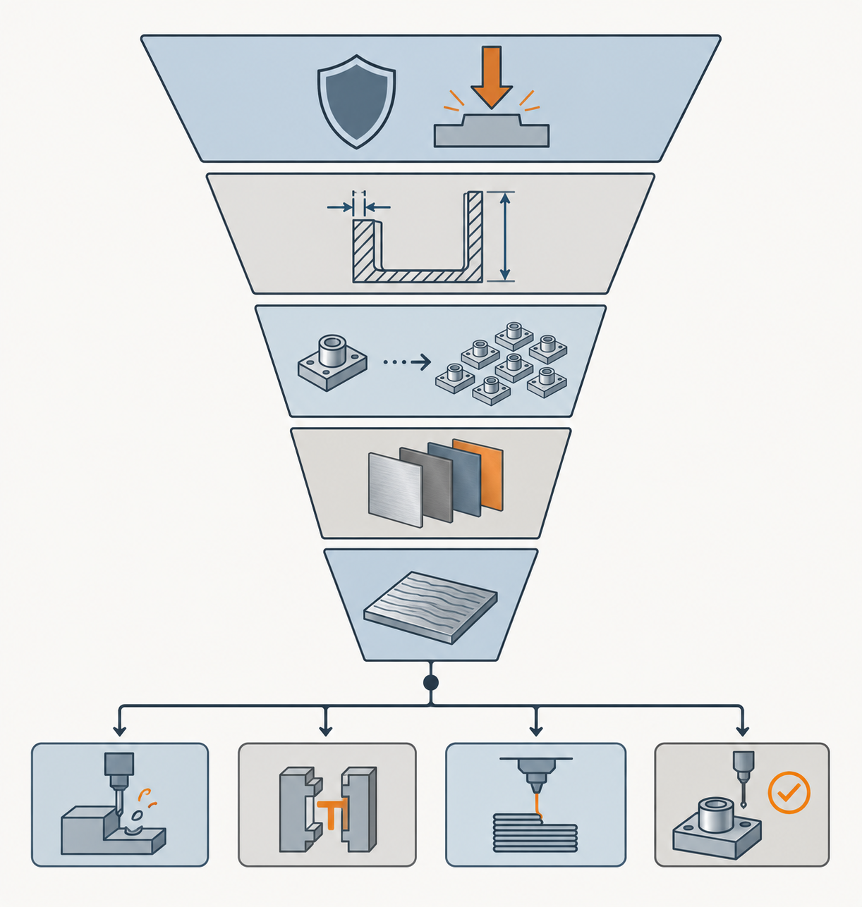
The previous sections broke down process selection from four angles: failure consequences, structural features, volume, and materials and post-processing. In actual work, these four angles are not parallel but a sequential filtering funnel: each layer passed leaves fewer candidate processes, and only what remains is worth quoting and prototyping. Fixing the order helps avoid the common mistake of "thinking of the process first, then finding reasons for it."
Layer one: function and failure consequences
First ask three questions: What are the consequences if this part fails? Is it subjected to static load, fatigue, impact, or purely assembly positioning? Are there any safety, sealing, or regulatory-related attributes? If the failure consequences are severe, process selection should lean toward "inspectable, traceable, and material-dense" rather than prioritizing cost. Conversely, for purely appearance parts or internal support parts, the process freedom is much greater.
Layers two through four: structure, volume, materials
The structure layer eliminates processes that "cannot be made" or "are extremely costly to make," such as closed cavities, deep narrow slots, and large thin walls. The volume layer determines whether tooling investment is worth amortizing; one-offs and low volumes usually fall to CNC, 3D printing, or urethane casting, while stable mass production is where injection molding and sheet metal tooling come in. The material layer then narrows the range in reverse: requirements such as high temperature, transparency, flame retardancy, and elastomers often leave only a few process routes to choose from. The order of these three layers can be swapped, but it is recommended to do structure before volume, because structural changes directly change the tooling plan.
Layer Five: Post-Processing and Verification Methods
The last layer is often skipped, yet it is the most likely to cause rework. Surface treatment, heat treatment, painting, silk screening, and assembly can all introduce new dimensional changes or appearance risks, and they can also constrain the preceding processes. At the same time, the verification method must be clarified: is it first-article full-dimensional inspection, functional testing, or scan comparison? Once the verification method is determined, the convergence speed of process recommendations will increase noticeably.
- Function and failure consequences: What happens if it fails? What is the load type? Is it safety-related?
- Structural features: Are there thin walls, deep cavities, internal right angles, enclosed cavities, or slender cantilevers?
- Quantity and stage: Single piece, low volume, medium volume, or stable mass production? Will there be revisions later?
- Material requirements: What are the hard constraints such as temperature, chemical resistance, transparency, flame retardancy, and elastomers?
- Post-processing and verification: What surface and heat treatments are needed? How is conformity confirmed?
After completing these five steps, you will usually get two to three candidate processes rather than a single "standard answer." This is normal—process selection is inherently a multi-solution problem, ultimately determined by cost structure, lead-time pressure, and risk preference. When rapid convergence is needed, you can directly submit the drawings together with the above information and let the engineering side provide a comparison of candidate processes, for example by first confirming the process boundaries through AI chat quoting or the manufacturing capabilities overview, and then moving on to a specific quote.
Common misjudgments: choices that look like they save money but are actually more expensive
Process misjudgments often occur not because of a lack of process knowledge, but because only the unit price was considered, not the total cost. The following types of misjudgments are very common during the inquiry stage, and their warning signs are also very typical.
Misjudgment 1: Using 3D printing for load-bearing parts
Warning sign: The part must withstand continuous load, impact, or repeated assembly, yet 3D printing is chosen directly because "printing is fast and no mold is needed." The interlayer bonding and anisotropy of additive manufacturing make performance in the load-bearing direction noticeably weaker than that of a dense part made from the same material. A more reasonable path is: use CNC machining for load-bearing areas, continue using 3D printing for non-load-bearing housings, brackets, and cable-routing parts, and assemble the two. If printed parts really must bear load, at minimum the load direction should be aligned with the print direction, and a verification step should be included.
Misjudgment 2: Using CNC for large-volume simple parts
Warning sign: The part has a simple structure and no complex curved surfaces, but the quantity has reached several thousand or more, and CNC is still used. At this point, per-part machining time is repeatedly consumed, while the upfront investment in molds or tooling has long since been amortized. A more reasonable path is to evaluate injection molding or sheet metal tooling; if the structure is truly unsuitable for mold making, then consider multi-station fixturing or dedicated jigs to compress per-part cycle time.
Misjudgment 3: Using injection molding for a few dozen parts
Warning sign: The quantity is only a few dozen parts, but a mold is made in advance because "injection molding will be used eventually." The upfront investment in the mold can hardly be amortized at this quantity level, and any design change directly becomes a mold modification cost. A more reasonable path is to first use rapid prototyping or 3D printing to verify structure and assembly, transition small batches with CNC or hand-made replica molding, and wait until the design is frozen and the quantity is stable before making a mold.
Misjudgment 4: Ignoring post-processing, leading to rework
Warning sign: When quoting, only the molding process is calculated, while painting, silk screening, heat treatment, deburring, cleaning, and assembly are all left to be discussed later. The result is that the molded parts are produced, but rework occurs because the surface condition, color batch, or assembly datum does not match. A more reasonable approach is to evaluate the entire post-processing chain when selecting the process: some surface treatments change dimensions, and some heat treatments cause deformation, so allowances must be reserved in the process route.
Misjudgment 5: Treating appearance parts as internal parts
Warning sign: The part will ultimately be seen by the user, yet the process and surface treatment are selected according to the standards for an internal structural part. Appearance parts are more sensitive to parting lines, gate locations, tool mark direction, and color differences. After choosing the wrong process, they often can only be salvaged through extensive polishing and touch-up painting, which actually costs more. A more reasonable path is: define the appearance surface grade separately, and when necessary split the appearance part and the structural part into two parts, each using the most suitable process.
What to prepare before quoting: making process judgment converge faster
The accuracy of process judgment depends to a large extent not on how strong the supplier is, but on how complete the information you provide is. For the same drawing, different accompanying information may change the recommendation from "CNC is recommended" to "it is recommended to modify the structure first and then make a mold." Preparation before quoting is not a procedural formality; it is about clarifying all the constraints needed for judgment at once.
Six types of information that must be provided
- Function and operating environment: What function the part serves, whether it bears load, whether it is a moving fit, and whether it contacts high temperatures or chemicals. This determines the baseline for material and process.
- Critical dimensions and datums: Which dimensions truly affect assembly and function, and where the datum surfaces are. Clearly marking critical dimensions is more useful than densely tolerancing the entire drawing.
- Appearance grade: Whether it is an appearance part or an internal part, which surfaces are visible, and whether tool marks, layer lines, or support marks are acceptable. Appearance requirements will directly eliminate some processes.
- Assembly relationships: Which parts it mates with, whether the fit is clearance, transition, or interference, and whether there are threads, snaps, or sealing surfaces.
- Quantity and stage: Whether it is currently in the verification stage or mass production stage, and the expected total volume and batch rhythm. The quantity range determines the timing of process migration.
- Post-processing and verification method: Whether surface treatment, heat treatment, painting, silk screening, or assembly is needed; whether the acceptable verification method is dimensional sampling, functional trial assembly, or scan comparison.
How information completeness affects recommendation quality
When information is missing, the engineering side can only make recommendations based on the most conservative assumptions—usually meaning a more expensive process or tighter tolerances to cover uncertainty. Conversely, when information is complete, the engineering side can proactively point out that "this feature can be relaxed" or "this surface does not need precision machining," thereby reducing cost while still meeting functional requirements. In other words, the closer the information you provide is to the real usage scenario, the closer the process recommendation will be to the optimal solution rather than the safest solution.
If you do not yet have a complete 3D model, you can also start communication with sketches, key dimension descriptions, and functional descriptions. The engineering side will use them to provide a preliminary process direction, and then refine it after the model is completed. The key is to first clarify function, quantity, and appearance, as these three have the greatest impact on process screening.
If you need to first understand the capability boundaries of each process, you can view the manufacturing capabilities overview, and then decide which items of information to supplement as priorities.
Frequently Asked Questions (FAQ)
The following questions basically cover the places where engineers and procurement staff most often get stuck during the process judgment stage. The answers try to provide judgment logic rather than conclusive numbers—for a specific part, confirmation is still needed based on the drawing and usage conditions.
Can the same part use different processes at different stages?
Yes, and it is very common. In the prototype stage, use 3D printing or CNC to quickly validate structure and assembly; for small-batch trial production, switch to silicone molding; once production is stable, move to injection molding or sheet metal tooling. This is a typical process migration path. Note that changing processes often means the material, surface condition, and some dimensional datums will change, so during the validation stage you should mark the critical mating surfaces and cosmetic surfaces to avoid discovering at mass production that parts do not fit.
If I don't have a 3D model and only have drawings or a physical object, can the process still be determined?
You can get directional guidance, but the accuracy is limited. 2D drawings can reveal structural features, critical dimensions, and material requirements, while a physical object can be reverse-modeled using 3D scanning and then enter process evaluation. When 3D data is missing, features such as deep cavities, internal channels, and freeform surfaces are easily underestimated. It is recommended to complete the model first before deciding the process; otherwise, quotations and actual machining are prone to deviation.
For small batches, should I choose CNC or silicone molding?
It depends on the structure and quantity. If the structure is simple, the material is mainly metal or engineering plastic, and the quantity is within a few dozen pieces, CNC is usually more direct and design changes are also flexible. If the structure is complex, has thin walls or fine textures, needs an appearance close to injection molding, and the quantity is between dozens and hundreds of pieces, the unit cost curve of silicone molding is often more favorable. The two can also be mixed: use CNC for load-bearing parts and silicone molding for cosmetic parts.
When appearance requirements are high, what should be noted in the process?
First clarify the appearance grade and visible surfaces, then choose the process. For injection molded parts, look at the parting line and gate location; for CNC parts, look at the tool mark direction and clamping marks; for 3D printed parts, look at layer lines and support residue; for sheet metal parts, look at bend radii and weld grinding. Cosmetic parts usually also require post-processing such as painting, screen printing, or brushing, and these operations should be considered together when selecting the process rather than added after the parts are made.
What should I do if the process recommendation and the final quotation do not match?
First confirm where the difference comes from: whether the quantity tier changed, a post-processing item was omitted, or the structure was modified again before quotation. Process recommendations are usually preliminary judgments based on drawings, while a formal quotation recalculates tooling, material utilization, and inspection requirements. Align the differences point by point, and if necessary, have engineering and the quoting party review the key features together; this is more effective than repeatedly comparing prices.
Key takeaways
- The first question in process selection is not "which process is good," but "what consequences would failure of this part cause." Function and failure consequences determine the lower limits of precision and material.
- Structural features often determine the process more than material does: thin walls, deep cavities, internal right angles, enclosed cavities, and large flat areas each rule out some processes.
- Quantity is the watershed: single pieces and prototypes prioritize CNC and 3D printing, small batches can consider prototype duplication, and stable mass production usually only then turns to injection molding and sheet metal tooling.
- Before requesting a quote, clearly stating the functional surfaces, datums, critical dimensions, appearance requirements, operating environment, and assembly relationships reduces total cost more than repeatedly comparing prices.
- There is no "optimal process," only "the least bad choice under current constraints"; it is normal and common for the same part to use different processes at different stages.



