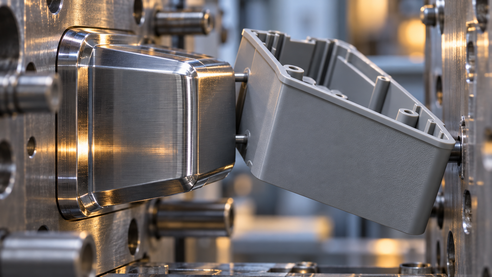
Why Your Product Always Gets "Bitten" by the Mold: The Essence and Cost of Draft Angle
The phrase heard most often on the shop floor is "it stuck to the mold again." Ejector pins that cannot push, whitened parts, scratched surfaces, and even push-through—behind these phenomena, nine times out of ten, is insufficient draft angle on the injection molded part. Demolding draft is not a decorative angle that may or may not be drawn on the drawing; it is a "separation agreement" between the product and the mold: at the moment the mold opens, the part must leave the cavity and core cleanly along the demolding direction, without dragging and without leaving scars.
When plastic cools and shrinks, it generates a clamping force against the core. Without draft, this clamping force is entirely converted into friction; combined with the vacuum suction formed between high-gloss surfaces, demolding resistance rises sharply. Based on industry experience, demolding force in a zero-draft design can be several times higher than with normal draft, accelerating wear on guide pillars, sliders, and ejection mechanisms and significantly reducing mold life; on the production line, this means yield may fall below 80%, and the costs of mold repair, downtime, and sorting eat into profits. How to determine draft angle for injection molded parts is therefore not a "close enough is fine" option, but a precondition that determines whether this mold can run through the order steadily.
Where the Cost Appears with Zero or Insufficient Draft
The cost has three layers. The first layer is product appearance: ejector whitening, scratches, haze spots, and localized gloss, with high-gloss parts and transparent parts especially sensitive. The second layer is the mold: roughened cores, damaged sliders, bent or broken ejector pins, and shortened maintenance cycles. The third layer is the process window: to demold, ejection force must be increased, ejection speed reduced, and cooling extended, stretching the molding cycle while yield may not recover. These three layers of cost are often chained; at first it is only "a little tight," and after tens of thousands of shots it becomes a major mold overhaul.
There Is No Universal Draft, Only a Matching Draft
Some people ask, "How many degrees should the draft angle be?" There is no single answer. The same 1° draft may be sufficient on a POM gear, but on an ABS housing with faux leather texture it will stick. Material friction coefficient, wall depth, surface texture, appearance grade, and dimensional accuracy requirements all change the answer. It is usually recommended that demolding draft be 1°–3°, with untextured side walls no less than 0.5°, and textured side walls requiring additional draft based on texture depth. These are common industry ranges; specific parts still need to be confirmed against drawings and materials.
The practice of treating draft as "add one degree uniformly at the end" often erupts during mold trials. A more reliable approach is to review demolding direction, parting line, material, and texture together during the DFM review stage, so that the draft angle of injection molded parts is justified from the design source, rather than modifying the mold after sticking occurs.
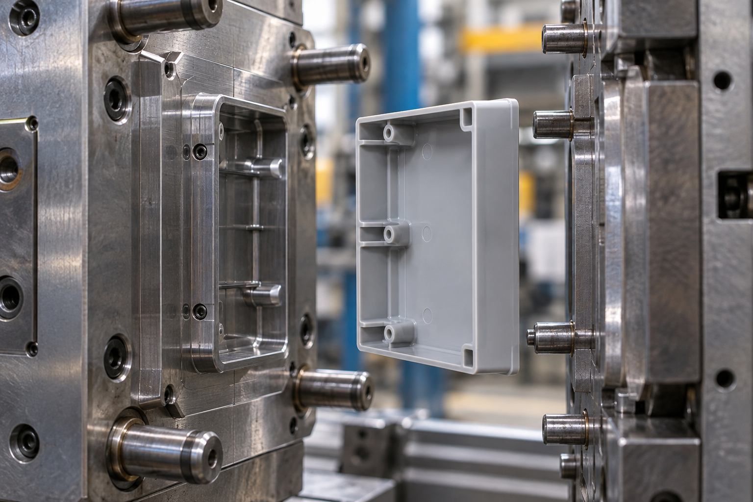
How to Determine Draft Angle for Injection Molded Parts: A Four-Step Decision Method
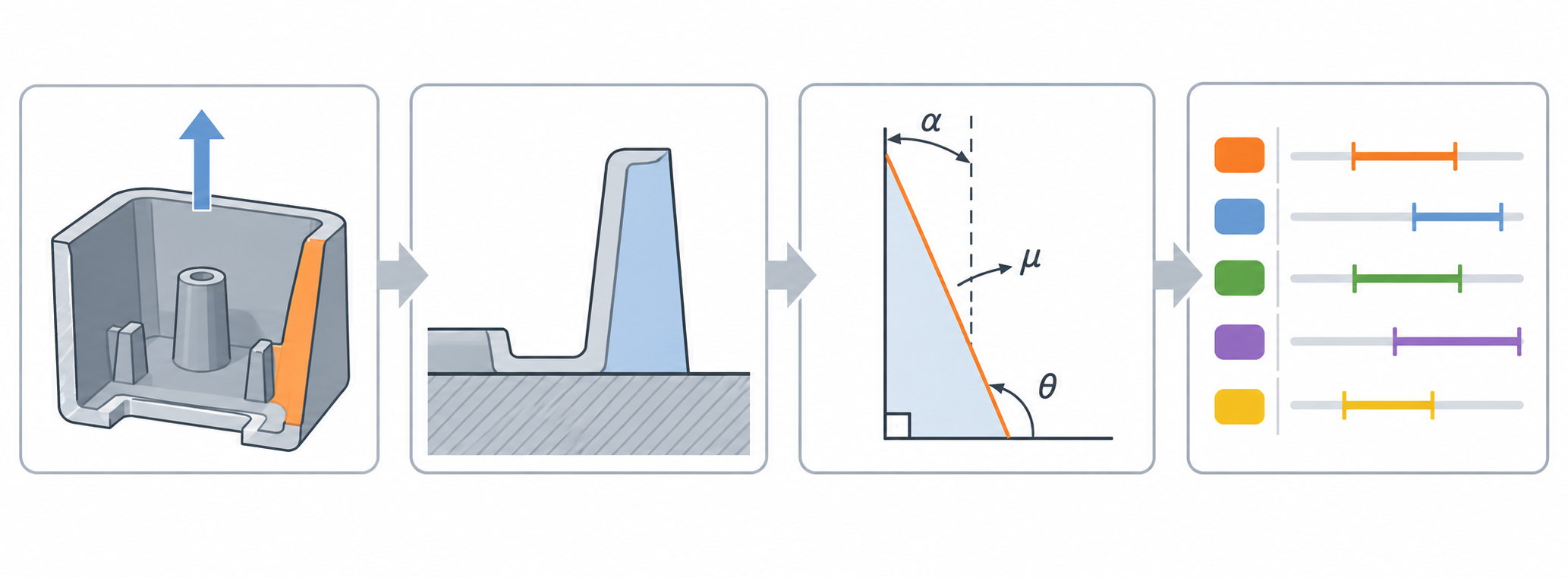
The common industry practice is to set the draft angle first and then draw the structure, but the truly reliable order is the reverse: first determine the demold direction, then choose the datum surface, then estimate the minimum draft angle, and finally correct it according to material and process. These four steps do not require complex software; a single sketch is enough to work it out. Each step below gives priority rules and check items so you can verify as you draw.
Step 1 Determine the demold direction: find the side with lower precision requirements
The demold direction determines the axis along which the part leaves the mold, and also determines which surfaces can be drafted and which surfaces will form undercuts. There is only one priority rule: choose the surface with the lowest dimensional precision requirement as the moving surface in the demold direction. Mating surfaces and appearance surfaces with high precision requirements should be placed as close as possible to the parting surface, and should not be pressed onto the long distance of the demold stroke.
Checklist: Are there surfaces on the product parallel to the demold direction? These surfaces must either be given draft or have their structure changed. Are there undercut features that require side core pulling or angled lifters? The undercut positions determine the draft design of the subsequent sliders and angled lifters. After the mold opens, does the part remain on the moving mold or the fixed mold? This affects the ejection mechanism and the direction of shrinkage deformation. If this step is not done correctly, the remaining three steps are all patching leaks.
Step 2 Choose the datum surface: large area, stable structure, and as parallel as possible to the parting surface
The datum surface is the starting point of the draft. In practice, give priority to a surface with a large area and stable structure, and keep it as parallel as possible to the parting surface—this way, after drafting, the largest dimension is close to the parting line, and shrinkage and ejection are more uniform. If the datum surface is chosen on a thin wall or a suspended structure, adding draft will instead pull the dimension chain off.
Checklist: Is the datum surface located near the parting surface? If it is a stepped parting surface, the shut-off area needs its own draft and cannot be mixed with the main datum. Will the distance from the datum surface to the parting surface cause a large dimensional deviation due to the draft? If so, consider moving the datum surface to the side closer to the parting line. Is the datum surface perpendicular to the demold direction? If not, it must be split into drafts in two directions and dimensioned separately.
Step 3 Estimate the minimum draft angle: the formula is only a starting point
The minimum draft angle is commonly estimated with this relationship: α_min = arctan(μ / cosθ). μ is the coefficient of friction between the plastic and the mold steel, and θ is the surface roughness compensation angle, which in industry experience is taken as 0.5°~1°. The physical meaning of this formula is very direct: the larger the friction coefficient and the rougher the surface, the larger the required draft. But the formula assumes a smooth surface, no texture, and no vacuum suction, and actual injection molded parts are rarely this ideal.
Therefore, the value calculated by the formula is only a lower-bound reference, and the final angle still depends on material shrinkage, texture depth, and ejection method. Checklist: Does the friction coefficient value match the actual material? Does the roughness compensation angle cover the actual machining state of the mold surface? Does the feature depth exceed the applicable range of the formula? If the depth exceeds about 50 mm, usually add another 0.5°~1° to the formula result. After calculating, cross-check with the material table in the next step.
Step 4 Adapt to material and process: check the table and correct, do not trust only the formula
With the same 1° draft, PP may release very smoothly, while a transparent PC part will show whitening. Material shrinkage, rigidity, and surface energy all affect demolding resistance. Common industry ranges for single-side draft: ABS about 1°~1.5° (for high-gloss surfaces, ≥2° is recommended), PP about 0.5°~1° (increased to about 1.5° with glass fiber), PC about 1.5°~2° (for transparent parts, the draft on both sides must be consistent), TPE about 2°~3°, POM about 0.5°~1°. These are starting points for judgment, not guaranteed values.
The process side also needs correction: when the surface has texture, add draft according to texture depth; for deep-cavity parts with a small ejection area, appropriately increase the draft; for high-speed injection molded thin-wall parts, the draft can be slightly smaller, but the ejection speed must match. Checklist: Do the recommended values in the material table cover the current wall depth? Is the texture depth supplemented according to the rule of adding about 0.4° per 0.1 mm? Does the ejection method (ejector pins, push plate, gas assist) match the draft? Stack the results of the four steps together, take the maximum value as the design draft, and then leave a little margin for trial-mold adjustment.
How to Choose the Datum for Demold Direction and Draft Direction
How to determine the draft angle for injection molded parts: the first step is not to draw the angle, but to first determine the demold direction and the datum surface. If the direction is wrong, all subsequent drafts will be reversed, and the mold will scratch as soon as it opens. Once the direction is set and the datum surface is chosen, the draft has a reference.
The draft direction faces the top of the mold, and the part is released in the direction away from the mold
A common industry practice is to orient the draft direction toward the top of the mold, so that during mold opening the part releases away from the mold, stays on the moving half, and is easy to eject. The way to judge this is intuitive: for a hollow box, the correct draft is an opening top slightly wider than the bottom—wide at the top, narrow at the bottom, so the box can slide off the core smoothly. If it is made narrow at the top and wide at the bottom instead, the part gets "bitten" onto the core, and during ejection it will either show stress whitening or be punched through.
There is a priority rule for choosing the demolding direction: choose the side with lower dimensional accuracy requirements as the demolding direction. This is because draft angles change dimensions, so the variation should be left in the direction with looser tolerances, and critical mating dimensions should avoid draft compensation as much as possible. At the same time, avoid undercuts—areas with undercuts cannot be solved by draft and must be handled by sliders or lifters.
Choose a datum surface that is large in area, structurally stable, and as parallel as possible to the parting plane
The datum surface determines from which line the draft is measured. In practice, give priority to a surface that is large in area, structurally stable, and as parallel as possible to the parting plane. Use the parting line as the datum and ensure that larger dimensions are close to the parting line, so that dimensional changes caused by draft are concentrated on the side away from the parting line, and mating dimensions near the parting surface are affected the least. If the datum surface is chosen on a small boss or thin wall, the draft will push that thin wall even thinner, creating new risks of sink marks and warpage.
Distinguish four types of draft angles: cavity, core, slider, and lifter
Once the direction and datum are determined, draft angles are divided into four categories by location, each with different forces and directions:
- Cavity draft angle: on the outer surface side, usually tapering toward the parting plane so the part can be released from the cavity.
- Core draft angle: on the inner surface side, in the opposite direction from the cavity, so the part can be released from the core. This is especially critical when the inner hole is deep; a deep hole without draft is very prone to scratching.
- Slider draft angle: at the side-action core-pulling area, in the direction of slider movement, to prevent dragging the product sidewall during core pulling.
- Lifter draft angle: the draft in the lifter ejection direction, which must match the lifter movement direction; otherwise it will scratch at the moment of ejection.
The common principle for all four types of angles is: the direction is based on the parting line, and larger dimensions are close to the parting line. Which surface belongs to the cavity and which belongs to the core must be clearly marked on the drawing before starting to draw the draft. The draft directions of the cavity and core are opposite; if marked incorrectly, the part will be gripped by both sides at the same time, and the demolding force will double.
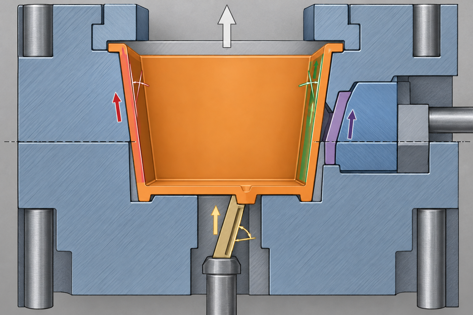
Once the direction and datum are fixed, subsequent draft estimation, material selection, and texture compensation have a stable reference. If these items are still fluctuating, do not rush to adjust the angle—go back to the model to confirm the demolding direction, then continue.
Minimum draft estimation: formula, friction, and vacuum suction
Now that the demolding direction and datum surface have been determined, the next step is to turn how to determine the draft angle for injection-molded parts into a specific number. In engineering practice, first use a formula to estimate a lower limit, then correct it based on material, texture, and depth. The formula gives a starting point, not the end point.
The friction formula tells you what the draft is resisting
During demolding, friction is generated between the plastic part sidewall and the mold steel, in the direction opposite to ejection. Simplified as f = μ × Fn × cosα: μ is the coefficient of friction between the plastic and the mold steel, Fn is the normal pressure of the sidewall against the mold (from shrinkage gripping force), and α is the draft angle. As the draft angle α increases, cosα decreases, and friction decreases accordingly. This is the most direct function of draft angle—turning sidewall contact from "surface friction" into "wedge separation."
Conversely, if the draft is zero, cosα = 1, friction is at its maximum, and at the moment of ejection there may be stress whitening, scratching, or even sticking to the mold. In industry experience, the demolding force on a side with no draft can be several times higher than with a 1°~2° draft; the exact multiple depends on the material shrinkage rate and surface roughness and cannot be generalized.
The physical meaning of α_min = arctan(μ / cosθ)
A commonly used estimation formula is α_min = arctan(μ / cosθ). μ is the coefficient of friction between the plastic and the mold steel, and θ is the roughness compensation angle, typically taken as 0.5°~1° in the industry to compensate for microscopic surface irregularities, mold release agent residue, and mold wear. This formula means: the greater the friction, the larger the minimum draft angle required; the rougher the surface, the larger the compensation angle.
The calculated α_min is only the theoretical lower limit. In actual drafting, a safety margin of 0.5°~1° is usually added on top, because the formula does not account for vacuum suction, micro-interlocking on textured surfaces, and ejection eccentric loading. Treat it as a "must not be lower than this value" check line, not as the final design value.
Vacuum suction on high-gloss surfaces: the invisible demolding resistance
On high-gloss or mirror-finish molds, the plastic part fits extremely tightly against the cavity, and at the moment of demolding a local vacuum forms between the two, creating additional suction resistance. This force is not included in f = μ × Fn × cosα, yet it is often the main cause of whitening/stress marks on transparent and high-gloss parts. The role of draft here is to give air a path to enter and break the vacuum; when the draft is insufficient, the vacuum suction may exceed the friction force itself.
Therefore, for high-gloss surfaces it is usually recommended to use a draft of 2° or more, combined with an appropriate ejection speed. If the speed is too fast, the plastic part does not have time to separate from the mold, and the vacuum suction is released in a concentrated manner, which easily causes whitening/stress marks; if the speed is slowed down, air has time to seep in, making demolding smoother.
Empirical comparison of feature depth and minimum draft
The deeper the side wall, the longer the demolding stroke at the same angle, the more pronounced the accumulated friction, and the required draft must be increased accordingly. Below is a commonly used set of empirical comparisons in the industry; the original data is in imperial units, converted here to metric and noted as empirical values:
| Feature depth | Recommended minimum draft | Notes |
|---|---|---|
| Approx. 6 mm | 0.5° | Shallow side wall, low demolding resistance |
| Approx. 13 mm | 1° | Common starting point for housing side walls |
| Approx. 19~38 mm | 1°~2° | Adjust according to depth and material shrinkage |
| Approx. 50 mm | 2° | Deep cavities require a larger draft angle to compensate for friction |
These numbers are only a starting point. At the same 50 mm depth, PP has high shrinkage and strong gripping force, so it may need more than 2°; ABS has low shrinkage, so 1.5° is sometimes enough. Ultimately, you still need to confirm against the material recommendation table and texture compensation rules.
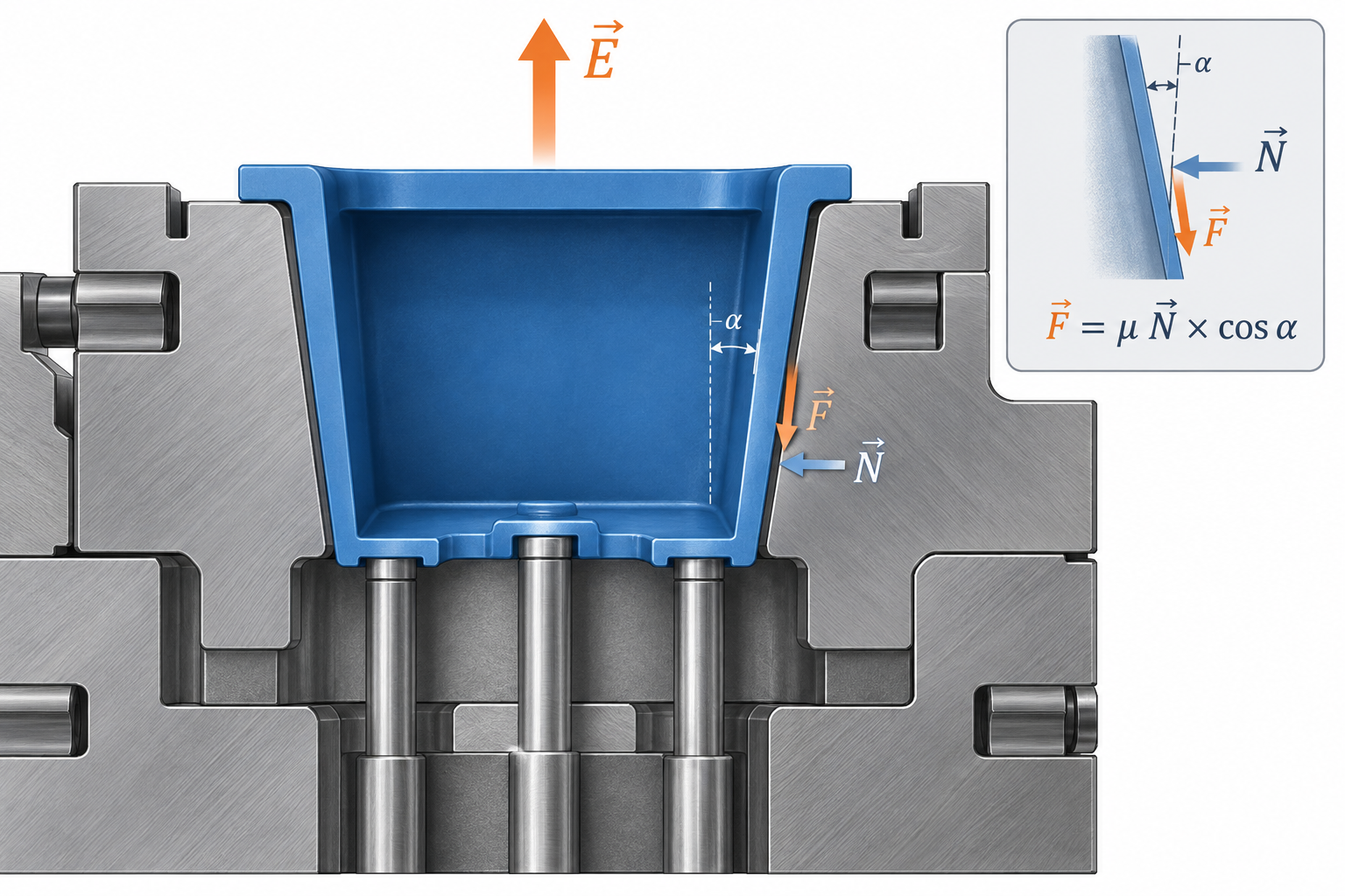
To sum up in one sentence: the formula calculates the lower limit, the depth table provides a reference, and vacuum suction and texture further revise it upward. How to determine the draft angle for injection-molded parts is never a matter of looking up a single number and being done; it requires factoring in friction, suction, material, and geometry together.
Materials and texture: quick reference for recommended draft angles of different plastics
The first four steps give the direction, the baseline, and the physical lower limit. When it comes to a specific part, you still need to answer a more practical question: for this plastic and this surface, exactly how many degrees should be given? The answer is not in the formula, but in the combination of the material's shrinkage rate, coefficient of friction, and texture depth. A common industry practice is to first check the material baseline value, then add increments item by item according to texture and appearance requirements.
Check the baseline by material: recommended single-side draft angles for different plastics
The following values are typical industry-recommended ranges (single-side angle, in degrees), used for quick judgment during quotation and DFM stages, and are not guaranteed company values; the final reference shall be the drawing annotations and mold maker review. For the same material, different grades and different flow directions can also lead to differences in demolding performance.
| Material type | Recommended single-side draft angle | Special requirements |
|---|---|---|
| ABS | 1°~1.5° | For high-gloss surfaces, ≥2° is recommended; avoid vacuum suction |
| PP | 0.5°~1° | When glass fiber is added, increase to about 1.5°; high shrinkage makes it prone to sticking to the mold |
| PC | 1.5°~2° | The draft on both sides of a transparent part must be consistent to prevent optical distortion |
| TPE | 2°~3° | Soft materials deform easily and need sufficient release before ejection |
| POM | 0.5°~1° | Self-lubricating and low friction, but textured surfaces still need added draft |
The most easily overlooked point in the table is the "consistent draft on both sides" for PC. Light refraction on both sides of a transparent part is extremely sensitive to wall thickness variation. With 1.5° on one side and 1° on the other, the wall thickness difference is amplified over a long flow path, appearing visually as flow marks or rainbow streaks. The 2°~3° for TPE is not conservative either; it is because soft rubber is more easily stretched and torn during ejection, and when the draft is insufficient, it deforms as soon as the ejector pin pushes.
Hidden rule for textured surfaces: add about 0.4° for every 0.1mm of depth
Texture, leather grain, and grid patterns directly "bite" into the mold. Industry experience: for textured sidewalls, add about 0.4° of draft for every 0.1mm of texture depth, equivalently about 0.25° for every 0.025mm of depth. The deeper the texture, the more microscopic undercuts there are in the demolding direction, and draft angle is what gives these undercuts room to escape.
Looking at texture depth and draft separately, the cost is very intuitive: when draft is insufficient, the demolding force can increase several times, and at the moment of ejection the part surface is scraped by the texture into bright marks; in severe cases, the entire textured surface is torn, and the mold must be stopped to repair the texture. Once texture depth is fixed at the etching stage, changing the draft later means changing the steel and electrodes, with costs far higher than adding half a degree during the design stage.
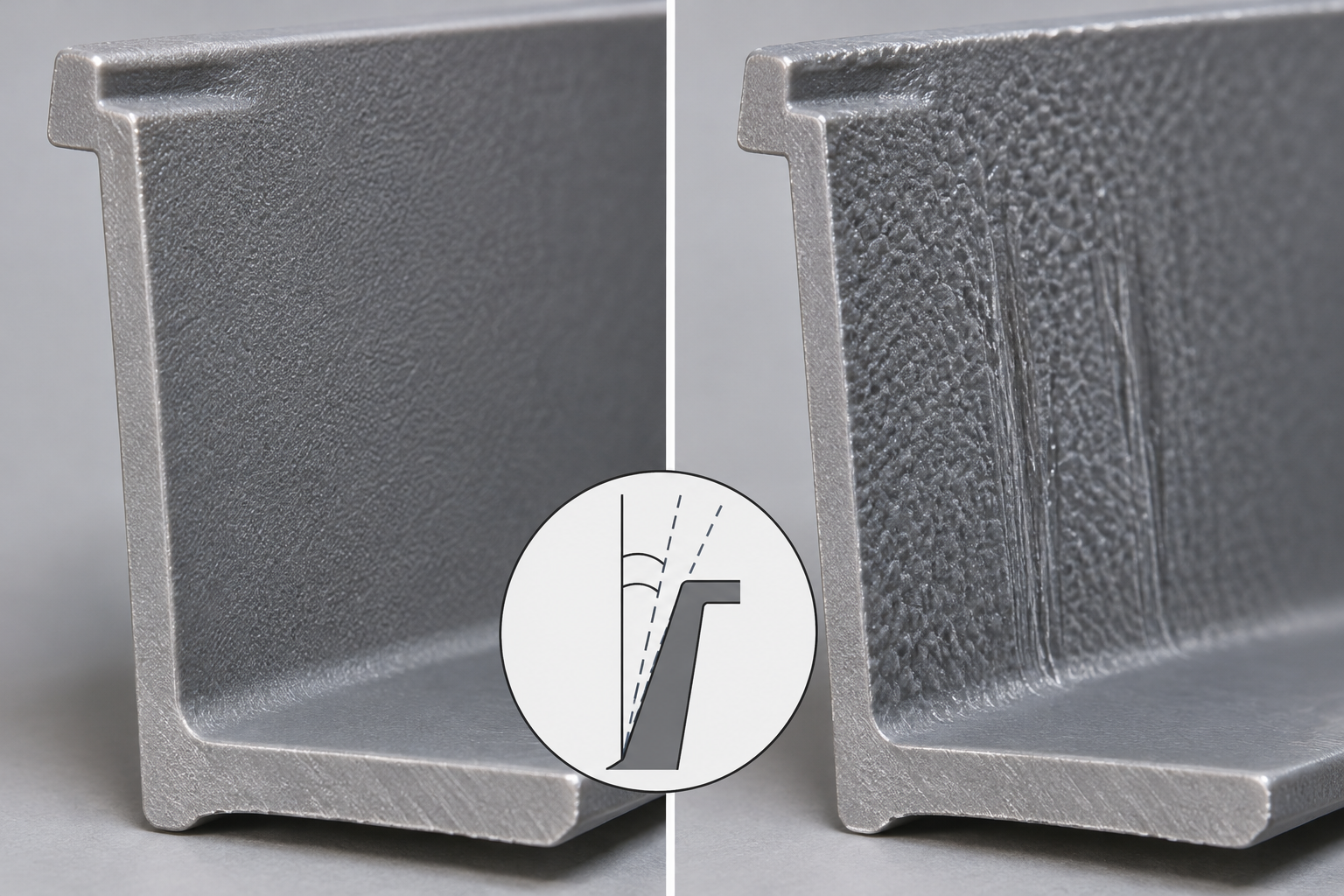
Recommended practical sequence: first assign the baseline draft according to the material table, then add based on texture depth, and finally verify against appearance requirements. For high-gloss surfaces, treat as ABS with ≥2°; for matte or leather-grain surfaces, add 0.4°~0.8° on top of the baseline. If you are doing a DFM-stage review, you can directly mark the draft for each sidewall against this table instead of waiting until the mold comes back to change it. When you need to check against a specific model, you can upload a 3D model to get DFM feedback.
Case study: rescuing grid-texture mold sticking and whitening on transparent lamp covers
The previous sections broke the logic of judging draft angle into direction, baseline, formula, and material table. But problems on the shop floor often do not appear by chapter: a mold passes trial and then suddenly starts sticking after three months of mass production; a transparent part runs fine for hundreds of shots, then whitens after switching to a new batch of material. The following two cases follow the four-part structure of problem—analysis—solution—result. The numbers come from publicly available case experience values, not guaranteed indicators from any factory, and are meant to help you judge whether your own parts have fallen into the same kind of pit.
Case 1: automotive instrument panel grid-texture part—why 0.8° draft could not survive mass production
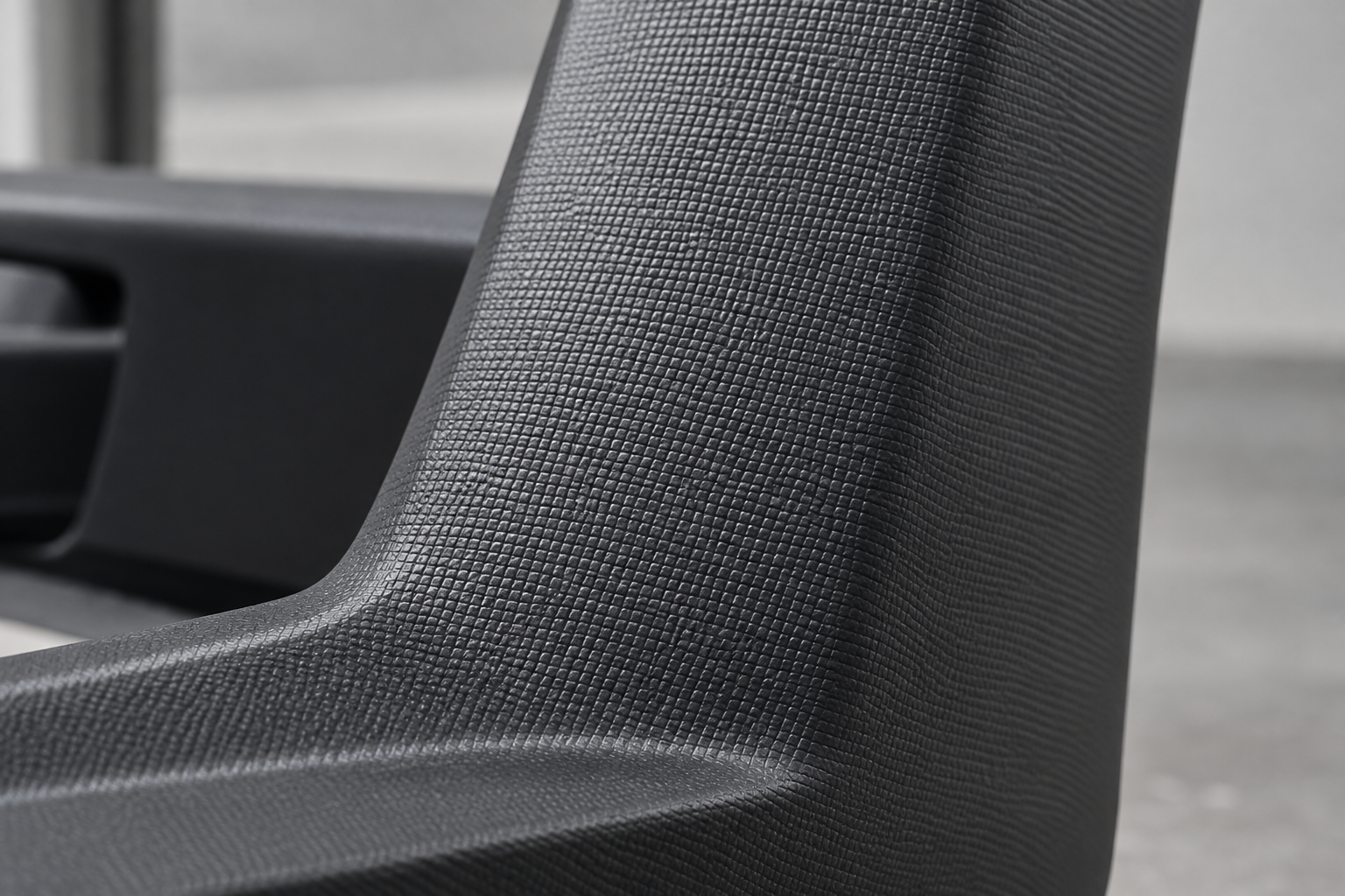
Problem. An automotive instrument panel trim part had a faux grid texture on the surface, and the initial sidewall draft angle was set to 0.8° based on experience. It barely ejected during trial molding, but after moving into mass production ramp-up, the yield rate dropped to about 65%. The main defects were local tearing after the grid texture was "bitten" by the mold, and local whitening during ejection. When the mold temperature was slightly higher or holding pressure was too high, the sticking rate rose noticeably.
Analysis. The value of 0.8° is not outrageous when looking only at sidewall depth; the problem lies in the texture. The grid texture creates a large number of tiny mechanical engagement surfaces on the sidewall. During demolding, friction is not just flat-surface friction but also local resistance caused by texture chamfers. The smaller the draft and the deeper the texture, the faster demolding resistance rises. When the mold engineer reviewed it, they found that the truly effective demolding area was much smaller than the theoretical sidewall area, with the actual force concentrated at the texture peaks. At the moment of ejection, local stress exceeded the material's yield point, so tearing and whitening appeared at the same time.
Solution. Do two things at once, rather than just adding draft. First, increase the sidewall draft angle from 0.8° to 1.5°, so that the textured surface develops a slight separation tendency the moment the mold opens, reducing engagement. Second, reduce the texture depth from about 2 mm to about 1.5 mm, lowering the height of each individual texture cell, which in turn reduces the mechanical resistance during ejection. At the same time, slow the ejection speed appropriately to avoid impact-style ejection amplifying localized stress.
Result. According to the case record, after adjustment the yield rate recovered to about 95%, and the ejection force dropped by about 40%. What is worth remembering here is not the number "1.5°" itself, but that textured parts cannot simply be forced through by adding draft: draft angle and texture depth are a set of parameters that need to be tuned together. Adding draft alone without changing the texture often yields only limited improvement.
Case 2: Whitening on a transparent PC lamp cover, draft from 1° to 2° plus speed reduction
Problem. A transparent PC lamp cover with high appearance requirements, with an initial sidewall draft angle design of 1°. During mold trials, radial whitening appeared near the ejection locations, visible to the naked eye, and optical inspection judged it unacceptable. Strangely, when the same mold ran opaque PC parts, the problem was almost invisible—the whitening was masked by the color.
Analysis. The "whitening" on transparent parts is essentially localized stress at the moment of ejection exceeding the material's yield strength, producing crazing or microcracks that scatter light and appear white. A 1° draft is not necessarily unusable on PC, but PC has high melt strength and is sensitive to shear, and the high-gloss surface easily forms vacuum suction, so demolding resistance is greater than for ordinary parts. An ejection speed of 50 mm/s is on the fast side, equivalent to adding another impact when the draft is already not generous.
Solution. Increase the draft from 1° to 2°, leaving a more comfortable separation stroke for demolding; reduce the ejection speed from 50 mm/s to 20 mm/s, giving stress time to release rather than concentrating it in an instant. Transparent parts also require the draft on both sides to be as consistent as possible, to avoid uneven stress on one side causing warpage or localized whitening.
Result. According to the case experience, the whitening disappeared and the appearance passed inspection. This case shows that draft angle and ejection parameters are a paired combination: the draft provides geometric margin, while ejection speed provides time margin. Adding draft without reducing speed, or reducing speed without adding draft, may only suppress the problem rather than solve it.
What the two cases have in common: draft angle is a system parameter, not an isolated number
Looking at the two cases together, the pattern is clear. First, texture and transparent appearance significantly change demolding difficulty; the same draft performs completely differently under different surface requirements. Second, draft angle, texture depth, ejection speed, and mold temperature are a set of mutually influencing variables, and changing one often requires changing another in coordination. Third, the 1.5°, 2°, 95%, and 40% in the cases are empirical values for specific parts, specific materials, and specific molds, and cannot be directly copied onto your drawings. What is truly transferable is the judgment method: first locate where the demolding resistance is concentrated, then decide whether to add draft, reduce texture, or adjust ejection.
If you currently have a similar part and are struggling over the draft value, you can hand the 3D model and appearance requirements together to the mold side for a demolding analysis, which is much faster than repeatedly guessing numbers on the drawing. When you have a specific part that needs draft angle evaluation, you can upload the model to the Get a Quote Now entry and note the appearance and texture requirements, so DFM feedback can help you set the draft within a reasonable range.
Draft over-limit challenges in special scenarios: texture, zero draft, and side core pulling
Textured surfaces: draft should be added according to texture depth, not chosen as a single number
Zero-draft no-go zones: how precision gears and optical lenses survive
- Forced demolding: leave the demolding stroke to the material's elastic deformation. It is suitable for thin-walled, tough materials (such as PP and some TPE), but ejection force and ejection speed must be calculated separately, otherwise whitening or ejection marks will occur.
- Sacrificial structure: machine the zero-draft face to a machinable allowance, then after demolding, rework it to size in a secondary operation; costly but reliable.
- Split the part or change the parting: move that feature onto a slider, lifter, or separate insert so the main body can still be demolded at a normal draft.
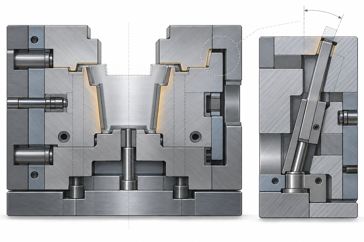
Side-action cores and lifters: angle limits and hard constraints in the shut-off area
Who should set the draft angle: the structural engineer or the mold engineer
Frequently asked questions (FAQ)
The following are several high-frequency follow-up questions around how to set draft angles for injection-molded parts. The answers are based on the four-step decision method, material and texture quick reference, and case experience in the main text; specific values still need to be confirmed against the part drawing and mold plan.
Is a larger draft angle always better?
No. A larger draft reduces demolding resistance, but it also changes the dimensions and appearance of mating surfaces. It is usually recommended to choose a value within the industry-common range of 1°~3°; an untextured sidewall can go as low as 0.5°, while a textured sidewall requires additional draft based on texture depth. If the draft exceeds the necessary value, it may produce visible taper on assembly surfaces or cause wall-thickness variation to exceed the tolerance band. A more robust approach is to first take the minimum sufficient value based on material and depth, then leave a safety margin of about 0.5°.
Will adding draft angle cause dimensions to go out of tolerance?
Yes, but it can be controlled. Draft is essentially a dimension that changes gradually along the demolding direction—the end near the parting line is larger, and the end away from the parting line is smaller. On drawings, mating dimensions are usually marked on the side near the parting line, or noted as "dimensions at the parting line shall govern." If the part has strict assembly-gap requirements, it is advisable to mark the datum surface during the DFM stage so the mold engineer can align the draft direction with the tolerance band, rather than forcing a fit later by reworking the mold.
Why do transparent parts need larger draft?
Transparent parts are more sensitive to surface defects. When draft is insufficient, local stress at the moment of ejection leaves stress whitening, silver streaks, or haze, and these are especially obvious on transparent PC and PMMA. In the case in the main text, a transparent PC lamp cover was increased from 1° to 2°, and at the same time the ejection speed was reduced from 50mm/s to 20mm/s, only then did the stress whitening disappear. In addition, transparent parts often require consistent draft on both sides to avoid distortion from light refraction. The specific angle still depends on wall thickness and gate location.
Can the minimum draft calculated by the formula be drawn directly on the drawing?
The formula α_min=arctan(μ/cosθ) gives a theoretical lower limit, not the final value. It only accounts for the coefficient of friction and the roughness compensation angle (commonly taken as 0.5°~1° in the industry), and does not factor in texture, vacuum suction, material shrinkage differences, or the ejection method. In actual drawing work, you usually need to add the texture additional angle on top of the formula result, then round it off against the material recommendation table. It is advisable to treat the formula as a starting point and the material table and depth table as the basis for finalizing.
If the draft on a textured part is insufficient, can it still be remedied later?
It depends on how much it is off. If it is only off by 0.2°~0.3°, it can sometimes be temporarily alleviated by reducing the texture depth, adjusting the ejection speed, or adding a release agent, but this is not a stable solution. If it is off by more, the mold usually needs to be reworked and re-EDM'd or the texture changed, which significantly increases cost. A more reliable approach is to reserve draft before mold making according to the rule of "add about 0.4° for every 0.1mm of texture depth," and to confirm the correspondence between texture depth and draft in the DFM feedback.
Key takeaways
- Draft angle is determined in four steps: demolding direction, datum plane, minimum draft estimation, and material and texture correction. First set the direction, then add the angle.
- In the industry, common single-side draft angles fall between 1° and 3°, with a minimum of about 0.5° for untextured side walls; the deeper the side wall and the coarser the texture, the greater the required draft.
- Textured surfaces typically require an additional approximately 0.4° per 0.1 mm of texture depth; stepped parting surfaces (shut-off areas) are often recommended to be 7° or more, with 5° regarded as the lower limit.
- Insufficient draft increases demolding force and aggravates scratching and vacuum suction; transparent parts, high-gloss surfaces, and glass-fiber-reinforced materials are especially sensitive to draft.
- Lifter angles are often kept within 12° in the industry to avoid self-locking; zero-draft areas require forced demolding or structural concessions in exchange.



