What Is Oxygen-Free Copper Material: Understanding Oxygen Content, Purity, and Common Grades
When connectors, busbars, leads, and heat-dissipating components require stable conduction of electrical current or heat, oxygen-free copper materials are often considered. Certain parts used in high-vacuum electronic equipment, electron tubes, and glass-to-metal seals also require attention to oxygen and impurity control in the copper material. Its value lies not in having the “highest strength,” but in the combination of low oxygen content, high purity, and electrical and thermal conductivity.
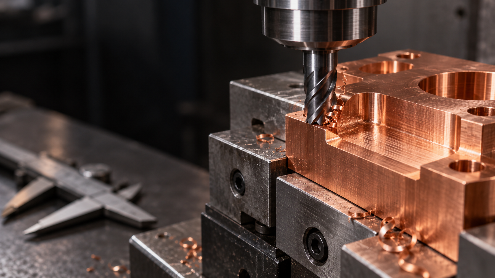
However, being suitable for functional parts does not mean being easy to machine. Oxygen-free copper is generally relatively soft and highly ductile, and CNC machining may result in tool adhesion, chip entanglement, burrs at hole openings, and surface scoring. The material name is only a starting point; the grade, supplied condition, and part structure all affect actual machining performance.
Oxygen Content and Purity: Confirm the Material Boundaries First
Relevant technical data often describes oxygen-free copper as a high-purity copper category with an oxygen content of approximately 0.003% or less and copper purity of approximately 99.95% or higher. However, these values should not be treated as universal specifications for all oxygen-free copper; oxygen content, impurity limits, and electrical conductivity should still be confirmed according to the applicable standard, specific grade, and material certificate. “Oxygen-free” does not mean that the material contains absolutely no oxygen; it means that the oxygen content is strictly controlled.
C10100 and C10200: Identification Starting Points Rather Than Simple Synonyms
Designations such as C10100 (OFE) and C10200 (OF) are commonly found in engineering documentation and can serve as identification starting points for selecting oxygen-free copper materials. However, they should not be directly equated with all red copper, pure copper, or other copper grades. Before placing an order, verify at least the following information:
- Grade, applicable standard, and the supplier’s material certificate;
- Supplied condition, such as annealed or cold-worked, and the corresponding hardness;
- Electrical conductivity, thermal conductivity requirements, and the part’s actual function;
- Plate, bar, tube, or custom billet form, along with the subsequent machining allowance.
If the part must also provide electrical conductivity, thermal conductivity, high-vacuum compatibility, or a sealing fit, the material certification, surface cleanliness, and acceptance criteria should be included in the drawing or purchasing requirements, rather than simply specifying “oxygen-free copper material.”
Why Oxygen-Free Copper Is Suitable for Part Machining: Electrical Conductivity, Thermal Conductivity, and High-Vacuum Requirements
The value of oxygen-free copper material is reflected first in its functional properties rather than its strength. Its low-oxygen, high-purity characteristics help maintain high electrical conductivity and good thermal conductivity, so it is commonly used for connectors, busbars, lead-type parts, heat sinks, and heat-exchanger components. Certain high-vacuum electronic equipment, electron tubes, and glass-to-metal sealing components also require attention to the material purity, low-oxygen characteristics, and surface cleanliness of oxygen-free copper.
Oxygen-Free Copper for Conductive Parts: Start with the Current Path and Contact Interface
For connectors, busbars, and lead-type parts, oxygen-free copper is typically selected to reduce losses along the conductive path and meet the contact requirements of terminals, holes, or lap joints. During machining, it is not enough to check whether the outer profile has been formed; the hole-entry burrs, groove-edge tearing, and flatness of the contact surfaces must also be inspected. Burrs may affect assembly clearances, while residual chips or surface contamination may alter the contact interface. Drawings should clearly specify critical contact areas, dimensional tolerances, deburring, and cleanliness requirements, rather than merely stating “oxygen-free copper.”
Oxygen-Free Copper for Heat-Dissipation Parts: The Thermal Path Matters More Than the Material Name
For heat sinks and heat-exchanger components, the key consideration is how heat travels from the heat source to the fins, base plate, or fluid-contact surface. Oxygen-free copper can meet high thermal-conductivity requirements, but thin walls, deep grooves, and large flat surfaces also introduce risks of warping, deformation, or poor contact. During design, unnecessary ultra-thin structures should be minimized, and space should be provided for tool access, chip evacuation, and subsequent deburring. After machining, flatness, groove continuity, and the contact condition with mating parts must also be verified. Good thermal conductivity does not mean that a part inherently has sufficient stiffness or wear resistance.
Oxygen-Free Copper Parts for High-Vacuum Applications: Purity and Cleanliness Must Be Confirmed Together
For parts used in high-vacuum electronic equipment, electron tubes, or glass-to-metal sealing applications, the material grade is only the starting point. Machining oil, residual chips, surface tearing, and improper cleaning may affect subsequent assembly or the operating environment. The material certificate, control of machining residues, cleaning process, and packaging method therefore need to be evaluated together. The fact that oxygen-free copper is suitable for these applications does not mean that an ordinary machined part automatically meets high-vacuum or sealing requirements; the final determination should still be based on the specific grade, part structure, surface condition, and acceptance specifications.
Challenges in CNC Machining Oxygen-Free Copper: Tool Adhesion, Chip Evacuation, Burrs, and Dimensional Stability
Oxygen-free copper is suitable for conductive, heat-dissipation, and certain high-vacuum-related parts, but that does not mean it is easy to cut. Oxygen-free copper is generally soft and highly ductile, making material adhesion likely during cutting. Once a built-up edge forms on the tool, chips may wrap around the tool or workpiece, causing chip-evacuation blockages, surface tearing, and dimensional variation. Before machining, the tool should be kept sharp, tool geometry suitable for copper should be used, and cutting parameters should be validated according to the grade, supplied condition, machine-tool rigidity, and tool condition. A standard speed or feed rate should not be applied without verification.
Tool Adhesion, Chip Evacuation, and Surface Quality in Oxygen-Free Copper Machining
Continuous chips from oxygen-free copper can easily accumulate in deep grooves, blind holes, and narrow cavities. Coolant delivery, airflow direction, and the tool’s chip flutes must be coordinated with the part structure; where necessary, deep grooves can be machined in stages to avoid cutting too deeply in a single pass. If drag marks, bright spots, or localized tearing appear on the machined surface, first check tool sharpness, chip adhesion, and clamping stability rather than simply increasing the feed rate. Flanging burrs can also easily form at hole entrances, groove edges, and outer profiles. During design, unnecessary extremely small radii should be avoided, and sufficient accessible space should be reserved for deburring.
Thin-Wall Deformation and Dimensional Stability in Oxygen-Free Copper Machining
Thin walls, slender parts, and large flat surfaces are sensitive structures in oxygen-free copper CNC machining. Clamping force may cause localized deformation, while cutting heat and material thermal expansion can cause dimensions to drift during machining. After the workpiece is released, springback or changes in flatness may also occur. A more reliable approach is to minimize overhang, use supports that conform to the workpiece, and apply an appropriate clamping force while separating roughing, semi-finishing, and finishing operations. Rough machining should first remove the major allowance, with critical dimensions completed after the workpiece temperature and stress state have stabilized. Critical hole spacing, flatness, and mating dimensions should be inspected in stages and, where necessary, remeasured after the workholding is released.
- [object Object]
- [object Object]
- [object Object]
- [object Object]
Which Machining Methods Are Suitable for Oxygen-Free Copper Parts: Milling, Turning, and Forming Routes
The machining route for oxygen-free copper parts should be determined first by their structure and function, and then by production volume. CNC milling is suitable for connector housings, busbar profiles, cooling grooves, and irregular blocks, allowing planes, hole locations, grooves, and local contours to be completed in a single setup. CNC turning is more suitable for axisymmetric joints, rings, sleeves, and parts with central holes. Oxygen-free copper is soft and highly ductile. When the route is not selected properly, the issue is usually not whether the material can be cut, but whether burrs, deformation, built-up edge, and critical dimensions can be controlled consistently.
How to Select Milling and Turning Processes for Oxygen-Free Copper Materials Based on Part Structure
When milling oxygen-free copper, deep grooves, small holes, and narrow ribs increase the difficulty of tool overhang, chip evacuation, and deburring at the same time. When turning thin-wall sleeves or rings, clamping force and cutting heat may cause changes in roundness, wall thickness, or end-face dimensions. Strictly controlled cosmetic surfaces also require attention to tool sharpness, tool-mark direction, and whether chips scratch machined surfaces. Therefore, the design phase should avoid thin sections that cannot be supported reliably, reduce unnecessary extremely small radii, and leave sufficient space for tool access and secondary deburring.
When to Consider a Forming Route for Oxygen-Free Copper Parts
Forming routes such as cold extrusion are generally more suitable for parts with relatively simple cross-sections and shapes and stable production volumes. Complex holes and grooves, irregular external profiles, or localized high-precision features often still require subsequent CNC machining. If die parting, demolding, or material flow is difficult to control, machining or a redesigned process split may be necessary. Forming does not mean that every complex structure will be more economical.
- [object Object]
- [object Object]
- [object Object]
How to Assess Applications of Oxygen-Free Copper Materials in Electronic, Electrical, and Thermal Management Parts
Applications of oxygen-free copper should be assessed based on the part’s function rather than simply by labels such as “pure copper” or “high conductivity.” Parts such as connectors, busbars, and leads typically require attention to current transmission, contact interfaces, and assembly stability. During machining, carefully check hole and groove locations, contact-surface flatness, and whether burrs remain at hole openings or on external profiles. Burrs may cause assembly interference or alter the contact condition. For contact parts requiring plating or other surface treatments, allowances should also be made for dimensional and interface changes after treatment.
Oxygen-Free Copper for Heat Sinks and Heat Exchanger Components
When oxygen-free copper is selected for heat sinks and heat exchanger components, the key objective is to establish a continuous and stable heat-flow path rather than to pursue material hardness. Machining drawings should clearly specify datum planes, groove continuity, flatness, and contact areas with mating parts. Thin-wall fins, deep grooves, and densely spaced channels are prone to warping due to clamping force, cutting heat, or poor chip evacuation. These risks can be controlled through proper fixturing, staged stock removal, and reinspection after releasing the workholding. Scratches at groove bottoms or residual burrs can also affect cleaning, contact, and subsequent assembly.
Oxygen-Free Copper for High-Vacuum and Sealing-Related Parts
Some high-vacuum electronic equipment, transmitting tubes, and glass-to-metal sealing components require attention to the low-oxygen characteristics and material purity of oxygen-free copper. However, an ordinary oxygen-free copper part does not automatically qualify as a high-vacuum component. For such parts, the material certificate, machining residues, surface condition, cleaning process, and packaging method must also be confirmed. Sealing surfaces require separate checks for scratches, burrs, and localized dents. If a part must provide high wear resistance, high load capacity, or long-term friction performance, the softness of oxygen-free copper may become a limitation, and copper alloys or other materials should be reconsidered.
Surface Treatment and Quality Inspection of Oxygen-Free Copper Parts: Returning from Functional Requirements to the Drawing
Surface treatment is not a default step for oxygen-free copper parts. Whether electroplating, polishing, sandblasting, or chemical treatment is required should be determined by contact resistance, corrosion resistance, sealing, appearance, and assembly requirements. Electrical contact surfaces may require control of the oxide film and interface condition; sealing surfaces require greater attention to flatness, scratches, and residues; and cosmetic surfaces should be protected against color variation, pitting, or dimensional changes after treatment.
Processing operations can change critical dimensions, surface roughness, and interface performance. Plating affects hole diameters, mating clearances, and contact dimensions; polishing may alter edge geometry; and sandblasting or chemical treatment may introduce particles and residues. Therefore, the surface-treatment name, coverage area, critical-dimension reinspection, and acceptance condition should be stated directly on the drawing or in the inspection requirements. A note saying only “surface treatment” in the purchasing remarks is not sufficient.
Key Post-Machining Inspection Points for Oxygen-Free Copper Materials
- Verify the grade, supply condition, and material certificate; “oxygen-free copper” cannot replace specific material requirements such as C10100 or C10200.
- Inspect critical dimensions, tolerances, flatness, hole and slot conditions, and assembly datums, paying particular attention to burrs at hole openings, slot edges, and the outer profile.
- Inspect for surface scratches, dents, discoloration, coating defects, and treatment residues; for functional components requiring electrical or thermal conductivity, also verify the applicable performance requirements against the drawings.
- Thin-walled oxygen-free copper parts should be remeasured after loosening the clamping and completing surface treatment to avoid misjudging dimensions due to clamping deformation or thermal conditions.
For high-vacuum or sealing-related parts, cleanliness requirements should be specified as clearly as the material and dimensions. Machining oil, abrasives, polishing compounds, fingerprints, and packaging particles may all affect subsequent use. The cleaning process, drying method, contact materials, packaging cleanliness requirements, and inspection method should be confirmed; cleaning an ordinary oxygen-free copper part does not automatically make it a high-vacuum-qualified part. Final acceptance should link the material grade, machined dimensions, surface condition, functional requirements, and cleanliness into a closed loop.
Common Issues in Oxygen-Free Copper Material Machining
The selection and machining of oxygen-free copper materials cannot be based on the material name alone. The material grade, supplied condition, part structure, functional requirements, and inspection plan must be confirmed together.
How should C10100 and C10200 oxygen-free copper be verified?
C10100 (commonly identified as OFE) and C10200 (commonly identified as OF) can serve as starting points for engineering identification, but orders should not be placed based on the names alone. The material certificate, applicable standards, oxygen content or purity limits, supplied condition, hardness, and electrical conductivity should be verified, along with whether these indicators meet the part's functional requirements.
Why is oxygen-free copper prone to tool adhesion and burr formation?
Oxygen-free copper is generally soft and highly ductile. During cutting, the material may adhere to the tool, and chips can easily become entangled; as a result, burrs are more likely to form at hole openings, slot edges, and the outer profile. The process should use sharp tools, improve chip evacuation and cooling, and adjust cutting parameters to suit the part structure. Machining conditions for ordinary steel should not be applied directly.
How can deformation risks be reduced in thin-walled oxygen-free copper heat sinks?
First, reduce unnecessary thin-wall and excessively deep-slot structures, then address clamping force, tool overhang, machining sequence, and allowance distribution. Stabilization and remeasurement can be arranged after rough machining. During finishing, avoid concentrated removal of allowance from one side; final dimensions should be based on inspection results after the clamping force has been released.
When should surface treatment and cleanliness be specified on the drawing?
When a part is used for electrical contact, sealing, corrosion resistance, appearance, or high-vacuum applications, surface treatment, roughness, residues, and cleanliness should be clearly specified on the drawing or in the acceptance requirements. Electroplating, polishing, sandblasting, and chemical treatment may change dimensions and interface performance, so critical dimensions should be rechecked both before and after treatment.
Key takeaways
- The core value of oxygen-free copper materials lies in the electrical conductivity, thermal conductivity, and partial high-vacuum compatibility enabled by their low oxygen content and high purity—not in high strength or easy machinability.
- C10100/OFE and C10200/OF can only serve as starting points for material selection. Ultimately, the material certificate, supplied condition, hardness, and electrical conductivity requirements should be verified.
- When CNC machining oxygen-free copper, tool sharpness, chip evacuation, clamping rigidity, thin-wall structures, and machining temperature should be controlled simultaneously.
- Connectors, busbars, heat sinks, and high-vacuum-related parts have different design priorities; material suitability cannot be judged solely by the industry designation.
- Surface treatment, cleanliness, and final inspection should be defined separately according to contact resistance, sealing, appearance, and assembly requirements.



