
Why Is PLA Suitable for Early Validation of FDM Functional Prototypes?
A PLA prototype may assemble smoothly at room temperature, yet its hole positions can gradually change when placed near a heat source or subjected to continuous load. This phenomenon shows that PLA is suitable for early validation of many functional prototypes, but that does not mean it is suitable for long-term service. If the validation targets appearance, assembly clearances, low-load operation, or a fixture concept, PLA is usually a convenient choice for rapid iteration; if the part must bear loads over an extended period, withstand repeated impacts, or operate in a high-temperature environment, the material should be reevaluated.
The Material Profile of PLA Functional Prototypes: Easy to Print but Limited Flexibility
From an engineering selection perspective, PLA’s typical properties can be summarized as follows: low printing difficulty, generally low shrinkage and warping, moderate strength, and relatively low flexibility. Some filament guides specify a typical process window of approximately 190–230°C for the nozzle and 35–55°C for the heated bed, but actual temperatures should be based on the specific filament datasheet, color formulation, and equipment parameters. Low warping helps maintain the external shape and assembly datums, making PLA suitable for quickly printing multiple versions during design iterations; however, its low flexibility also means that snap fits, thin walls, threads, and structures subjected to repeated disassembly and reassembly are more prone to fracture or chipped edges.
What Can PLA Validate, and What Can It Not Replace?
Accordingly, PLA functional prototypes should first serve specific validation tasks: confirming appearance and proportions, checking assembly relationships, evaluating the feel of low-load operation, or verifying whether a fixture concept can locate a part. PLA can help identify interference, incorrect hole positions, and insufficient operating space, but it cannot automatically prove that the final part has adequate long-term load-bearing capacity. In particular, when the load-bearing direction does not align with the print orientation, interlayer bonding, wall thickness, and infill pattern will all affect the result. Before submitting a print, it is best to specify the load, operating temperature, contact time, and critical dimensions on the drawing or in the notes, to avoid mistaking “easy to print” for “suitable for every engineering application.”
How Does the Forming Mechanism of FDM-Printed PLA Affect Functional Prototype Performance?
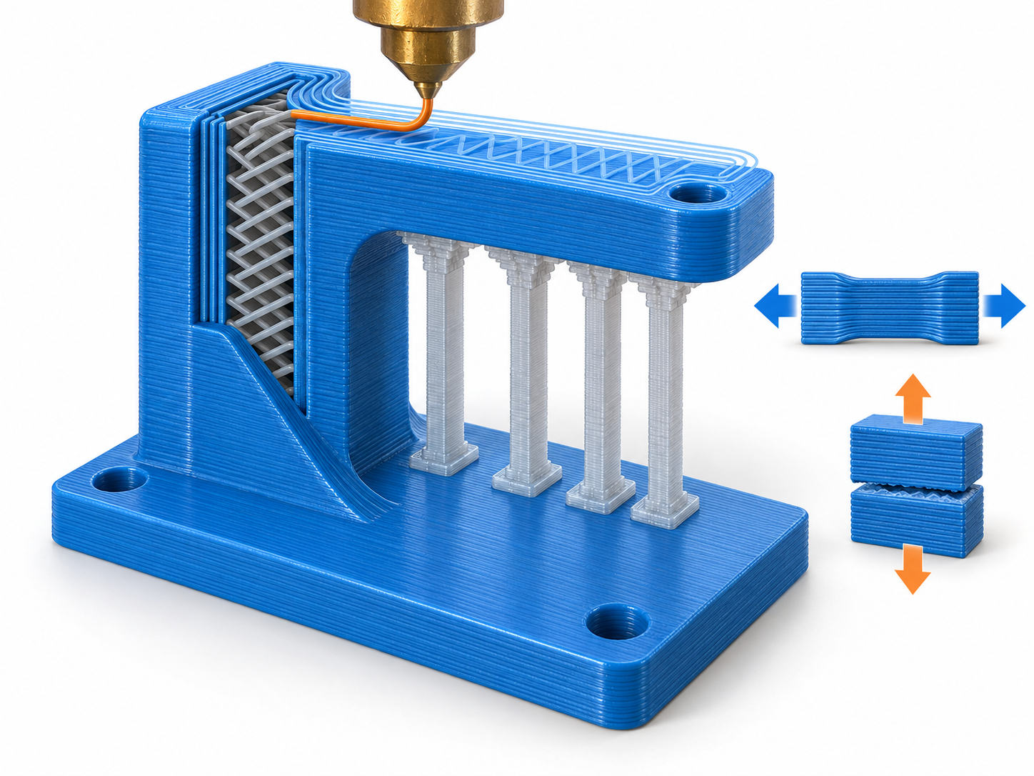
Determining whether a PLA functional prototype can be used requires more than looking at the material name; the way the part is printed must also be considered. FDM typically begins by slicing the CAD model to generate the nozzle’s movement paths. The filament melts in the nozzle and is deposited along the paths to form one layer, which is then stacked layer by layer to create the part. If overhangs, holes, or complex curved surfaces lack self-support, support structures must be added. This process means that an FDM part is not a homogeneous injection-molded component.
Interlayer Bonding and Load Direction in PLA Functional Prototypes
Within the XY plane of the same layer, the molten filament can generally form continuous paths, whereas strength in the Z direction depends on the bonding between adjacent layers. Therefore, when tensile, bending, or clamping forces act primarily across the interlayers, the strength and fracture risk may differ from those in the XY direction. Print orientation, layer height, number of walls, infill pattern, and cooling conditions all affect actual performance. Thin-walled parts may become soft because of an insufficient number of walls, long cantilevers are prone to sagging, load-bearing holes may deform under load, and threads may fail because of interlayer delamination or insufficient material in local areas.
Reverse-Engineering a PLA Printing Strategy from Part Features
For example, the same PLA bracket may exhibit different bending behavior when printed flat versus upright; when the hole axis is parallel to the Z direction, the hole-wall toolpath, support requirements, and interlayer bonding can also affect the assembly result. When designing a functional prototype, first clarify whether the goal is to validate appearance, assembly clearance, low-load operation, or load-bearing capacity and long-term durability, and then determine the print orientation and structural parameters. Layer lines, support marks, and local dimensional deviations are not accidental defects but process results of FDM layer-by-layer fabrication. A material that is easy to print can lower the barrier to prototyping, but it cannot replace analysis of load direction and validation objectives.
What Factors Affect the Dimensional Accuracy of FDM-Printed PLA Functional Prototypes?
PLA's low shrinkage and low warping help maintain the overall form, but this does not mean that every local feature will achieve the same dimensional result. FDM first slices the CAD model and then uses the nozzle to melt and extrude material along a toolpath, depositing it layer by layer; the nozzle diameter, layer height, extrusion flow rate, and cooling conditions all affect the actual material accumulation at edges, corners, and thin walls.
Hole diameter is a common source of deviation. The inner-wall toolpath must change direction within a limited space, and the molten material may expand slightly toward the inside of the hole; horizontal holes are also affected by bridging, supports, and layer lines. Thin walls may become thicker or thinner because they cannot accommodate a complete extrusion line, while overhangs and long cantilevers are prone to sagging, vibration ripples, or localized damage after support removal. When the print orientation changes, the hole's roundness, the flatness of long edges, and dimensional stability under load may also change.
| Feature | Primary risk | Recommended validation method |
|---|---|---|
| Hole and shaft-hole fit | Inner-wall toolpath, shrinkage, and orientation may cause the hole diameter to be undersized or out of round | Measure the hole diameter on the first article, then test-fit it with the actual shaft or a plug gauge |
| Thin walls and snap-fit slots | Nozzle width, flow rate, and cooling may cause wall-thickness deviations | Measure the wall thickness and conduct assembly and repeated disassembly tests |
| Overhangs and support surfaces | Sagging, layer lines, and damage from support removal may affect the profile | Inspect critical surfaces; adjust the orientation and remeasure if necessary |
| Long edges and datum surfaces | Deformation caused by warping, interlayer shrinkage, or uneven platform adhesion | Measure flatness and endpoint distance to confirm the assembly datum |
Therefore, FDM dimensional accuracy should be managed by feature rather than judged solely by the material name or appearance. Drawings should preferably distinguish critical dimensions, assembly dimensions, and non-critical external profiles: hole diameters, mating clearances, and datum surfaces should have acceptance methods defined before printing; ordinary curved surfaces and non-functional appearance features can use broader acceptance criteria. A neat-looking surface only indicates that the forming condition is relatively good; it cannot replace measurements with calipers, micrometers, plug gauges, or dedicated inspection fixtures.
What dimensional accuracy can PLA achieve in FDM printing? How should acceptance methods be established?
“PLA has good dimensional stability” does not mean that all features can achieve the same tolerance. FDM parts are formed by depositing molten filament layer by layer, and the nozzle diameter, layer height, extrusion flow, print orientation, cooling, shrinkage, and support removal all affect the final dimensions. The approximately ±0.2 mm value commonly cited in industry materials can serve only as a rough reference. Actual results also depend on the equipment, part size, geometry, and process settings, and it cannot be used as a guaranteed value for all PLA parts.
First distinguish critical dimensions from non-critical external profiles
Before printing, the drawing or inspection requirements should identify critical hole diameters, shaft-hole fits, assembly clearances, datum surfaces, and flatness. External curved surfaces or non-assembly areas can use relatively lenient requirements; load-bearing holes, locating-pin holes, and screw engagement positions should be confirmed separately. Hole diameters may be undersized because of inner-wall toolpaths, material accumulation at corners, and cooling shrinkage. Thin walls, long edges, and overhanging areas are also prone to localized deformation. Before adjusting slicing parameters, first clarify which dimensions actually determine the assembly result.
Establish PLA acceptance criteria using test specimens and first articles
For PLA functional prototypes with fit requirements, it is recommended to first print a test specimen containing holes, shafts, thin walls, and datum surfaces, or to use the first article directly to confirm the compensation direction. During measurement, select calipers, micrometers, plug gauges, or dedicated inspection fixtures according to the feature, and record the hole diameter, shaft-hole fit, clearance between adjacent parts, screw engagement condition, and flatness. Assembly validation should also record whether forced insertion is required, whether interference occurs, and whether the fit changes after several assembly and disassembly cycles. If critical dimensions consistently fail to meet requirements, processes such as CNC machining should be evaluated instead of continuing to modify slicing parameters alone.
| Acceptance item | Recommended method |
|---|---|
| Critical hole diameters and shaft holes | Measure with plug gauges, calipers, or micrometers, and complete an actual fit-up test |
| Assembly clearance | Measure the clearance between adjacent parts and check for localized interference |
| Datum surfaces and flatness | Measure with the part in a stable resting state; use a dedicated inspection fixture when necessary |
| Appearance and non-critical curved surfaces | Check the profile, layer lines, and support marks; this does not replace acceptance of critical dimensions |
How are PLA heat-resistance limits jointly determined by temperature, load, and time?
A PLA functional prototype assembling properly at room temperature does not mean it can operate near a heat source over the long term. Data indicates that standard PLA has a heat deflection temperature of approximately 50°C under a 0.45 MPa load. This value comes from specific test conditions and can only serve as a risk indicator; it should not be regarded as a universal continuous-use limit for all PLA grades, print orientations, and loads.
Softening, heat deflection, and melting are not the same thing for PLA
A part does not need to approach its melting point to fail. As the temperature rises, PLA's stiffness may decrease; under sustained static loading, creep may also occur, causing hole positions to gradually shift, clamping force to decrease, or flat surfaces to warp. Short-term contact with a heat source without load generally presents less risk than continuous clamping. For short-term assembly at room temperature, focus on verifying fit dimensions; however, near heat sources, in sun-heated vehicles, or in periodically high-temperature environments, temperature, load, and exposure time must all be considered.
How should the thermal limits of a PLA functional prototype be verified?
Verification should record not only the ambient temperature but also the specific filament grade, infill percentage, wall thickness, print orientation, and load location. For prototypes involving continuously clamped parts, load-bearing brackets, or components near heat-generating elements, first conduct short-term tests at the actual temperature and load, then inspect the hole diameter, flatness, assembly clearance, and changes in clamping force. If the function depends on long-term loading, repeated thermal cycling, or high-temperature stability, standard PLA generally should not be used as the default final material. Instead, comparative testing should be conducted with candidate materials such as PETG, ABS, nylon, or PC.
Which PLA functional prototype scenarios should prompt priority consideration of a material change?
The point at which a PLA functional prototype should be replaced with another material should not be determined solely by material strength rankings; it should be based on how the part is likely to fail. If the prototype must operate under sustained high temperatures, in a sun-heated vehicle, under impact loading, through repeated snap-fit cycles, under long-term clamping, with high-friction wear, or in contact with chemical media, standard PLA is generally not the first choice. Low warpage and ease of printing can help accelerate structural validation, but they do not mean that the part has long-term load-bearing, impact-resistance, or environmental-resistance capabilities.
Moving from low-impact validation to PETG functional prototypes
If the main issues are easily broken snap-fits, an increased number of assembly and disassembly cycles, or the need for the part to withstand more significant impacts, PETG can be evaluated as the next candidate after PLA for a functional prototype. PETG generally offers greater impact toughness and durability than PLA, but it is also more susceptible to moisture, placing higher demands on drying, extrusion control, and surface finish. After changing materials, do not directly carry over the original wall thickness, print orientation, or dimensional compensation; it is best to revalidate using the actual assembled part.
High-temperature, outdoor, and engineering load-bearing applications require a redefinition of FDM material selection
For functional prototypes intended for outdoor use, ASA can be evaluated. When toughness, chemical resistance, or long-term loading is the priority, nylon can be considered; when greater temperature stability is required, ABS or PC may be appropriate directions to explore. These are not simply “upgraded versions” of PLA, but materials that bring new process requirements, potentially including stricter drying, an enclosed printing environment, warpage control, and support strategies. Before switching materials, confirm the temperature, load duration, impact frequency, wear mechanism, and acceptance dimensions, then make a decision through sample testing.
- [object Object]
- [object Object]
- [object Object]
How should PLA, PETG, and engineering-grade FDM materials be selected?
Material selection for a PLA functional prototype should not focus on “strength” alone. First clarify the validation objective, then assess temperature, load duration, impact, durability, dimensional stability, printing difficulty, and quantity together. For low-temperature, low-impact, short-term appearance, or assembly validation, PLA is usually the first material to consider. When greater impact toughness and durability are needed, PETG can be evaluated. For higher temperatures, outdoor exposure, or long-term engineering loads, ABS, ASA, nylon, or PC should be further evaluated, based on data for the specific grade and sample testing.
| Validation Conditions | Preferred Consideration | Engineering Judgment |
|---|---|---|
| Room temperature, short term, low load, with appearance or assembly as the primary focus | PLA | Dimensional stability and printability are generally favorable, but hole diameters and fit clearances still need to be checked |
| Applications involving impact, repeated assembly and disassembly, or extended service life | PETG or other tough materials | Pay attention to moisture absorption, print control, and interlayer bonding; materials should not be compared solely by name |
| High temperatures, outdoor weather resistance, sustained loading, or wear resistance | ABS, ASA, nylon, PC, etc. | Revalidate based on heat resistance, weather resistance, chemical resistance, and equipment conditions |
Pre- and post-print inspection of PLA functional prototypes
Before printing, first confirm the filament technical data sheet, drying and storage conditions, and lock in the load-bearing direction, wall thickness, infill pattern, and critical dimensions. After printing, do not only check whether the surface is intact; measure the hole diameter, datum surfaces, fit clearances, and, where necessary, flatness, then perform actual assembly, screw engagement, or snap-fit assembly and disassembly tests. If the part will contact a heat source, short-term validation should also be performed at the actual temperature, load, and duration. When changes in hole position, loss of clamping force, or interlayer cracking occur during testing, first determine whether the issue is related to the structure and print orientation or whether PLA's temperature and toughness limits are no longer suitable.
- Low temperature, low impact, and short-term validation: prioritize evaluating PLA.
- Increasing impact and durability requirements: evaluate PETG and check the filament condition.
- High temperature, outdoor use, or long-term loading: reevaluate engineering-grade FDM materials and the printing equipment conditions.
- If critical dimensions cannot be consistently confirmed through first-article measurement: do not rely solely on slicer compensation; reevaluate the process.
Frequently asked questions about selecting PLA for functional prototypes
PLA functional prototypes are suitable for low-temperature, low-impact, and short-term validation, but assembly fixtures, precision holes, or use in thermal environments should not be evaluated based solely on the material name. The print orientation, wall thickness, load, temperature, and duration should be checked together, and critical dimensions should be measured on the first article.
Can PLA be used for assembly fixtures?
It can be used for room-temperature, low-load, short-term positioning or assembly concept validation, but it is not suitable for fixtures used for long-term clamping, load-bearing, or repeated impact. The primary loads should be carried by continuous outer walls and stronger interlayer directions, and the design should be validated through actual assembly, clamping duration, and the number of assembly and disassembly cycles.
Why can holes printed in PLA be smaller than the CAD dimensions?
Internal holes are affected by nozzle diameter, extrusion flow rate, layer height, print orientation, cooling, and hole-wall toolpaths. Low shrinkage does not mean that all hole diameters will automatically be reproduced accurately. The hole diameter should be measured on the first article, and, where necessary, a test-hole array should be used to determine dimensional compensation rather than directly applying a uniform tolerance.
Can PLA prototypes be left inside a car?
It is not recommended to judge this solely based on assembly results at room temperature. Exposure to direct sunlight inside a car can produce high temperatures, and if the part is also subjected to clamping forces or sustained loads, it may soften, creep, develop changes in hole positions, or warp. Short-term display without a load and long-term installation are different operating conditions, so validation should be conducted under the actual temperature and load conditions.
When should you switch from PLA to PETG?
When a functional prototype begins to require greater impact toughness, repeated assembly and disassembly, or longer-term durability, PETG can be evaluated. If the primary concerns are high temperature, outdoor weather resistance, or structural loads, ABS, ASA, nylon, or PC should also be compared. After switching materials, moisture absorption, warping, print orientation, and critical dimensions must be reconfirmed.
Key takeaways
- PLA’s key advantages are low warping, ease of printing, and fast iteration, making it suitable for appearance, assembly, and low-risk functional validation.
- FDM dimensional accuracy is not determined by the material alone. The nozzle, layer height, print orientation, hole diameter, thin walls, supports, and post-processing all affect acceptance results.
- PLA’s thermal limits should be evaluated together with temperature, load, and time; a heat-deflection value of approximately 50°C can only serve as a reference under specific test conditions.
- Applications involving repeated snap-fit cycles, impact, long-term clamping, high temperatures, or outdoor use require reevaluation of materials such as PETG, ABS, ASA, nylon, or PC.
- Before batch printing, first lock down the critical dimensions, print orientation, and actual operating conditions, then confirm the solution through first-article measurement and assembly, temperature, and load testing.



