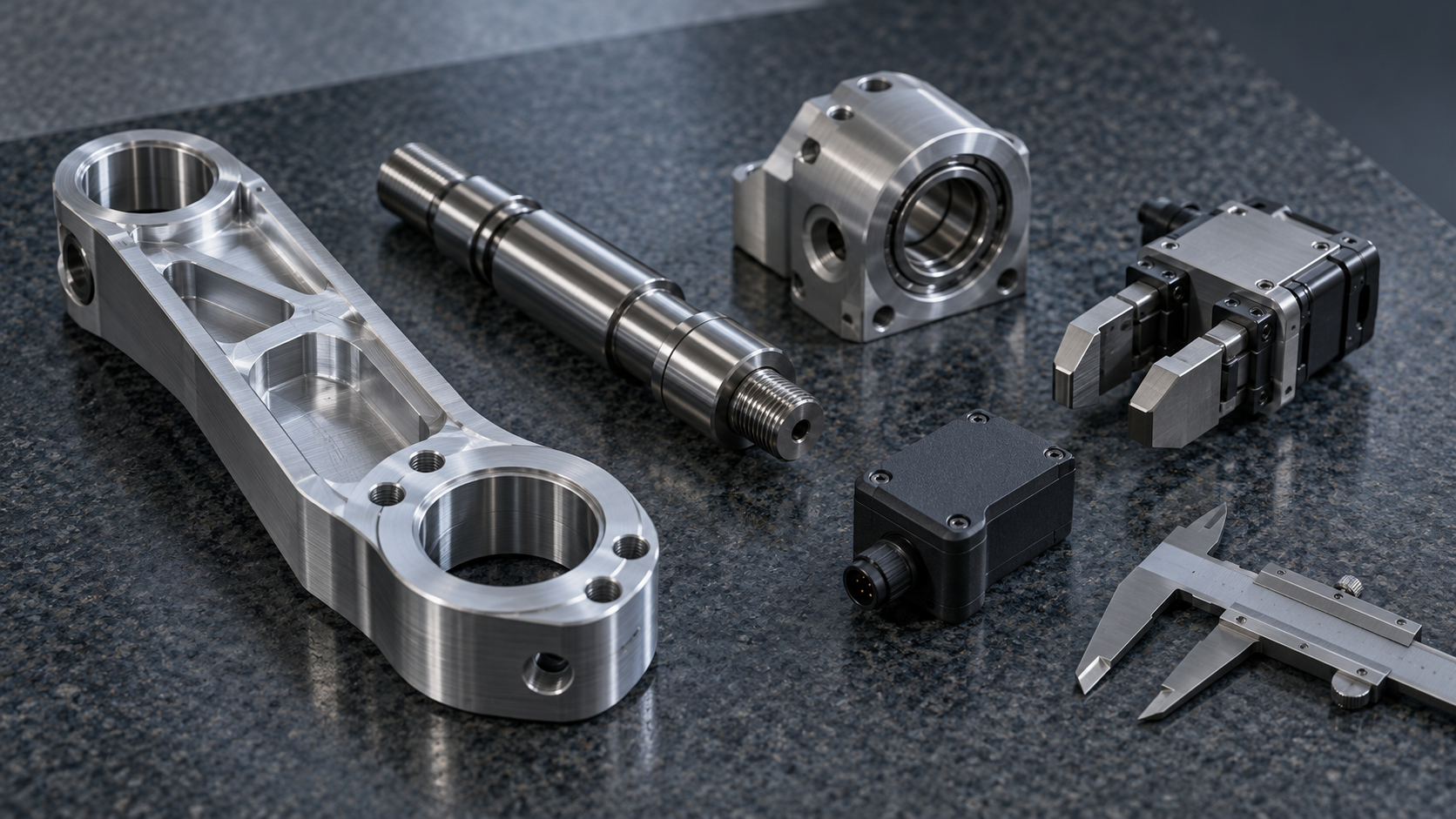
What Typical Robotic Components Are Included in Robotic Component Machining? Start with Functional and Geometric Classification
Why can the machining route be completely different even for robotic components? A robotic arm connection plate typically requires multiple mounting faces, locating holes, and weight-reduction cavities; a precision shaft focuses on rotational surfaces, fit sections, and concentricity; an end-effector gripper must balance gripping rigidity, weight, and mounting-hole locations; and a sensor enclosure places greater emphasis on protective structures, cable passages, and interface locations. They all serve robotic motion, but their load conditions, geometries, and functional surfaces are not the same.

Therefore, robotic component machining should not begin with the question of “which machine to use”; it should first confirm the part’s role within the system. Robotic arms, bases, and joint housings often include planes, hole patterns, curved surfaces, and locating features on multiple faces; shafts, sleeves, and other rotational components are generally evaluated first for turning; gears, bearing housings, and gearbox housings also require attention to meshing, assembly, and relative datums. End effectors and custom fixtures may use milling, additive manufacturing, or a combination of processes, depending on load, weight, production volume, and structural complexity.
When evaluating a process, functional datums are more important than the part name. For components that must support stable, repeatable motion, the key considerations may be the relationships between bearing seats, mounting surfaces, and locating holes, rather than applying the same tolerance band to every surface. The starting point for robotic component machining is to distinguish load-bearing surfaces, motion and fit surfaces, assembly interfaces, and acceptable non-critical areas, then determine the route in combination with the material, quantity, and inspection method. Only in this way can a manufacturable balance be achieved among rigidity, alignment, wear resistance, and weight.
Which Machining Methods Are Suitable for Different Robotic Components?
Robotic component machining does not begin by specifying a particular machine; it begins by evaluating the part’s shape, loading conditions, production volume, and assembly requirements. Robotic arm connection plates, bases, and joint housings typically include planes, hole patterns, curved surfaces, and multiple mounting faces. CNC milling is suitable for machining these features from metal or engineering-plastic stock; when the positional relationships between multiple faces are important, fixturing and datum transfer should be key topics during process review.
Robotic Component Machining: How to Choose Among Milling, Turning, and Five-Axis Machining
Rotationally symmetric components such as shafts, sleeves, and pins are generally evaluated first for turning, followed by subsequent operations for features such as keyways, cross-holes, or end-face holes. Five-axis machining is suitable for parts with continuous curved surfaces, numerous angled holes, or a need to reduce the number of setups. However, not every robotic component requires five-axis machining; if a three-axis or four-axis machine combined with suitable fixturing can establish datums reliably, adding axes unnecessarily may instead increase programming, fixturing, and inspection complexity.
Robot Part Machining: The Boundaries of 3D Printing, Sheet Metal Fabrication, and Injection Molding
Complex lightweight brackets, enclosure prototypes, and low-volume validation parts can be evaluated for 3D printing, which is particularly suitable for rapidly modifying geometry. However, once the parts enter a stage requiring load-bearing capacity, wear resistance, or high dimensional stability, CNC machining or other processes still need to be reconsidered. Thin-sheet guards, brackets, and housings can be produced through sheet metal fabrication, with cutting, bending, and welding used to form the structure. High-volume plastic housings are typically evaluated for injection molding, provided that the parts have appropriate wall thicknesses, draft directions, and mold parting conditions. In other words, complex geometry is not necessarily better suited to additive manufacturing, and increasing production volume does not mean that every structure should immediately move to tooling.
Why Is CNC Machining Commonly Used for Robot Parts?
CNC machining is commonly used for robot parts not only because of its “high precision,” but also because it can directly machine metals or engineering plastics according to structural and functional requirements while maintaining good dimensional consistency for low-volume production, customization, and multiple iterations. Parts such as robotic arm mounting plates, joint housings, and mounting bases typically contain planes, hole patterns, steps, and local curved surfaces, making them suitable for CNC milling. Precision shafts, sleeves, and pin-like parts are more similar to solids of revolution and are generally considered first for turning. Five-axis machining can then be evaluated for complex multi-sided features or when reducing the number of setups is necessary, rather than assuming that more axes are always required.
The Value of Robot Part Machining Lies in Datum Relationships
The results of robot part machining also depend on the fixturing and datum strategy. The offset of hole positions relative to mounting surfaces, the coaxial relationship between bearing seats and end faces, and the spacing between multiple locating holes all affect final assembly and motion repeatability. If a part must be turned over multiple times, datum transfers may accumulate errors; appropriate fixturing helps enable continuous machining of critical surfaces. During engineering reviews, dimensional accuracy, positional accuracy, repeatability, surface roughness, and assembly fits should be evaluated separately. Standard structural parts do not necessarily require the same tolerance grades as bearing seats, joint mating surfaces, or gear-related components.
Robot Part Machining Must Match the Material and Iteration Pace
CNC milling and turning are suitable for producing custom parts from plate, bar, or block stock. Materials can be selected from options such as aluminum alloys, steel, stainless steel, and engineering plastics, but the decision cannot be made independently of load, stiffness, weight, wear resistance, and the operating environment. For prototypes and low-volume production, CNC machining often makes it convenient to modify drawings quickly and reuse machining approaches. Complex lightweight structures can also be validated first with 3D printing before determining whether to switch to CNC machining or another production process. Anodizing, electroplating, painting, or heat treatment should likewise serve goals such as wear resistance, corrosion resistance, friction control, or appearance, rather than being treated as default steps in robot part machining.
Which Geometric Features in Robot Part Design Are Most Likely to Increase Machining Difficulty?
The difficulty of robot part machining often does not come from the complexity of the overall shape itself, but from the inability of the tool to approach steadily, insufficient workpiece support, or datum transfer after multiple setups. Design reviews should first ask: Does this feature serve a load-bearing, assembly, cable-routing, or motion-related function? If it has no clear function, complex geometry usually only increases machining and inspection risks.
Deep Cavities, Radii, and Deep Holes in Robot Part Machining
Deep, narrow cavities limit the tool diameter and the tool overhang. The smaller the tool and the longer its overhang, the weaker its rigidity generally becomes, while chip evacuation also becomes more difficult, making chatter, tool wear, and unstable cavity-wall dimensions more likely. An excessively small internal radius may likewise require the machining provider to use a smaller tool, increasing the number of toolpaths and the inspection difficulty. If the structure permits, increase the radius or design a tool-accessible relief groove at the corner. For deep holes, chip evacuation during drilling, hole-axis deviation, and subsequent measurement must all be considered; simply specifying a hole diameter in the model is not sufficient.
How Thin Walls and Multi-Angle Features Affect Robot Part Machining
Thin-walled parts may deform under cutting and clamping forces and spring back after the load is released. Insufficient wall thickness can also amplify vibration, making results for flatness, profile, and hole position unstable. Adequate support should be maintained during fixturing, and the machining sequence should be adjusted when necessary to avoid weakening the workpiece before machining critical surfaces. Angled surfaces, angled holes, and multi-sided features without a functional basis increase the difficulty of angular positioning, datum transfer, and fixture-gauge design. Robot part machining is not more advanced simply because it involves more angles: prioritizing tool accessibility, clear datums, and continuous machining of critical surfaces is generally more reliable than pursuing complex geometry.
Key Considerations for Machining Robot Parts for Joints, Reducers, and End Effectors
Robot part machining cannot apply the same precision logic to every component. Joint housings, precision shafts, gear-related parts, and end effectors perform different functions, and the dimensions, datums, and surfaces that truly require control also differ. When evaluating machining results, the part should be considered within the chain of bearings, reducers, assembly, and motion testing, rather than judging only whether one dimension was “made accurately.”
Robot Part Machining for Joint Housings and Bearing Seats
For joint housings and bearing seats, the key concerns are typically the bearing seats, mounting surfaces, locating holes, and the relative positions within the hole pattern. A bearing bore meeting its dimensional specification does not necessarily mean that the assembly will run stably. The coaxial relationship of the holes, the perpendicularity between the end face and hole axis, and the positional errors between multiple mounting datums are equally important. The machining process should arrange fixturing around the primary datums to minimize unnecessary datum transfers. For deep-cavity or thin-walled housings, deformation caused by cutting and clamping forces must also be evaluated, and functional dimensions should be distinguished from general external dimensions on the drawing.
Robot Part Machining for Precision Shafts, Gears, and Reducer-Related Components
For precision shafts and sleeve-type parts, turning is generally considered first, followed by milling or other processes as needed for keyways, hole positions, or end-face features. The focus is not limited to outside-diameter dimensions; rotational accuracy, fit clearance, shoulder positioning, surface condition, and wear resistance are also important. Gear- or reducer-related components require simultaneous attention to meshing relationships, mounting datums, and material condition. Even if an individual tooth profile or hole position meets specification, insufficient assembly coaxiality can still cause noise, backlash, or motion errors. Specific tolerances, heat treatment, or surface treatment cannot be determined independently of the load, rotational speed, lubrication, and inspection plan.
End effectors and fixtures place greater emphasis on weight, rigidity, gripping surfaces, mounting-hole locations, and ease of changeover. Lightweighting cannot simply be equated with reducing wall thickness; doing so may reduce clamping rigidity or cause vibration. For sensor housings, the mounting interface, protective structure, cable routing, and operating environment should be confirmed first. Protection, sealing, or insulation requirements must be clearly defined during the drawing and material-selection stages. Therefore, the key to robot parts machining is not pursuing extreme tolerances on every surface, but allocating machining requirements around assembly datums, motion relationships, and inspection methods.
How can robot parts machining balance precision, rigidity, weight, and cost?
Robot parts machining should not begin by specifying the material and then requiring all dimensions to use the same tolerance scheme. Aluminum alloys, steel, stainless steel, and engineering plastics are only candidate categories; the final selection must account for load, rigidity, weight, wear resistance, corrosion resistance, friction conditions, and the operating environment. A joint housing may need to minimize weight while maintaining the stability of its mounting surfaces, whereas precision shafts place greater emphasis on rotation, fit, and wear resistance. Sensor housings may instead prioritize protection, insulation, or cable routing.
Production volume and iteration stage also affect the process route. Prototypes and small-batch parts are generally better suited to initial evaluation through CNC machining or 3D printing: the former facilitates stable datums and surfaces, while the latter is suitable for validating complex geometries, lightweight structures, and assembly relationships. For high-volume plastic parts, injection molding is typically evaluated further, but tooling, draft direction, wall thickness, and shrinkage must all be considered. Surface treatment should not be added by default; it must be clearly determined whether it serves wear resistance, corrosion resistance, friction control, appearance, or insulation.
Precision trade-offs should start with functional tolerances and critical datums rather than forcing every dimension to an extreme limit. The relationships among bearing seats, locating holes, mounting surfaces, sealing surfaces, and gripping surfaces should be clearly defined, while measurement datums, inspection fixtures, and assembly verification should be considered simultaneously at the drawing stage. Dimensional accuracy, positional accuracy, repeatability, surface condition, and fit results need to be evaluated together. Investment in robot parts machining delivers real value only when the tolerances can be machined, inspected, and translated into assembly performance.
What information should be prepared before submitting robot parts machining samples?
Before submitting samples, do not provide only a 3D model. Process reviews for robot parts machining should generally proceed in the order of “geometry—functional datums—material condition—production volume—inspection requirements.” The more complete the information, the easier it is to determine which features are suitable for milling, turning, or additive manufacturing, while also reducing repeated confirmations caused by unclear datums.
Drawings and models required for robot parts machining
The 3D model is used to identify the overall structure, cavity depth, wall thickness, and tool accessibility. The 2D drawing should clearly define dimensions, tolerances, datums, surface roughness, threads, chamfers, and special requirements. Clearly identify bearing seats, locating holes, mounting surfaces, sealing surfaces, and gripping surfaces, and explain their fit or positional relationships. Do not assign the same grade of extreme tolerance to every dimension; functional tolerances are more conducive to fixturing, machining, and inspection.
What other operating conditions should be specified during a robot parts machining review?
The information should also include the material and its condition, expected quantity, surface treatment, operating environment, load, motion frequency, and assembly relationships. If the part involves repeatable positioning, rotary fits, wear resistance, or sealing, the corresponding validation priorities should be specified. At the same time, confirm in advance which dimensions require inspection reports, coordinate measuring machine measurements, or dedicated inspection fixtures. The final process route should be determined jointly by the drawing, material, production volume, and critical datums, rather than by specifying a particular machine or single process in advance.
Common questions about robot parts machining
There is no universal process for robot parts machining. Whether CNC machining, five-axis machining, or 3D printing is appropriate should be determined based on the part's function, geometry, material, production volume, assembly relationships, and inspection conditions.
Are all robot parts suitable for CNC machining?
Not necessarily. Metal or engineering-plastic parts such as robotic-arm connectors, bases, joint housings, shafts, and sleeves can generally be evaluated for CNC milling or turning. Complex lightweight structures, prototypes, and low-volume parts may also be better suited to 3D printing. The final decision depends on the material, loading, dimensional stability, surface requirements, and quantity.
When is five-axis machining required?
Five-axis machining can be evaluated when a part has machining surfaces in multiple directions or complex curved surfaces, or when reducing fixturing and datum transfers is desirable. However, not every robot part requires five-axis machining. If three-axis machining or conventional multi-face fixturing can reliably complete the critical holes, planes, and mating surfaces, a simpler process is usually more conducive to controlling fixturing and inspection risks.
Can 3D-printed parts be used directly for load-bearing joints or end effectors?
They must be validated based on the material, print orientation, interlayer strength, load, wear resistance, and operating environment; appearance alone is not sufficient for judgment. 3D printing can be prioritized for prototype validation, light-duty fixtures, and complex internal structures. For load-bearing joints, bearing seats, or high-frequency moving components, CNC machining, injection molding, or metal manufacturing options should be compared further, followed by assembly and service-life validation.
How can you determine whether the tolerances on a robot parts drawing are reasonable?
First distinguish functional tolerances from non-functional dimensions, with particular attention to bearing seats, locating holes, mounting surfaces, sealing surfaces, clamping surfaces, and the positional and concentric relationships between them. Tolerances should also be matched to the material, machining process, fixturing method, and inspection datums. Applying limit tolerances to all dimensions does not necessarily improve robot motion performance; it is recommended to confirm the inspection methods and assembly requirements at the drawing stage.
Key takeaways
- Robotic component machining should begin by evaluating function, geometry, production volume, and critical datums before selecting a process; not every part requires five-axis machining.
- Robotic arm connectors and housings are typically machined primarily by CNC milling, while shafts and sleeves should be evaluated first for turning. Five-axis machining should be considered for complex features on multiple faces.
- 3D printing is suitable for prototypes, low-volume production, and complex lightweight structures; load-bearing, wear-resistant, dimensionally stable, or high-volume plastic parts require a renewed evaluation of CNC machining or injection molding.
- Deep, narrow cavities, excessively small internal radii, thin walls, and unnecessary multi-angle features increase the difficulty of tool access, vibration control, deformation control, fixturing, and inspection.
- The focus in robotic component machining is not to pursue extreme tolerances in isolation, but to coordinate critical datums, fits, repeatability, surface condition, and inspection plans.



