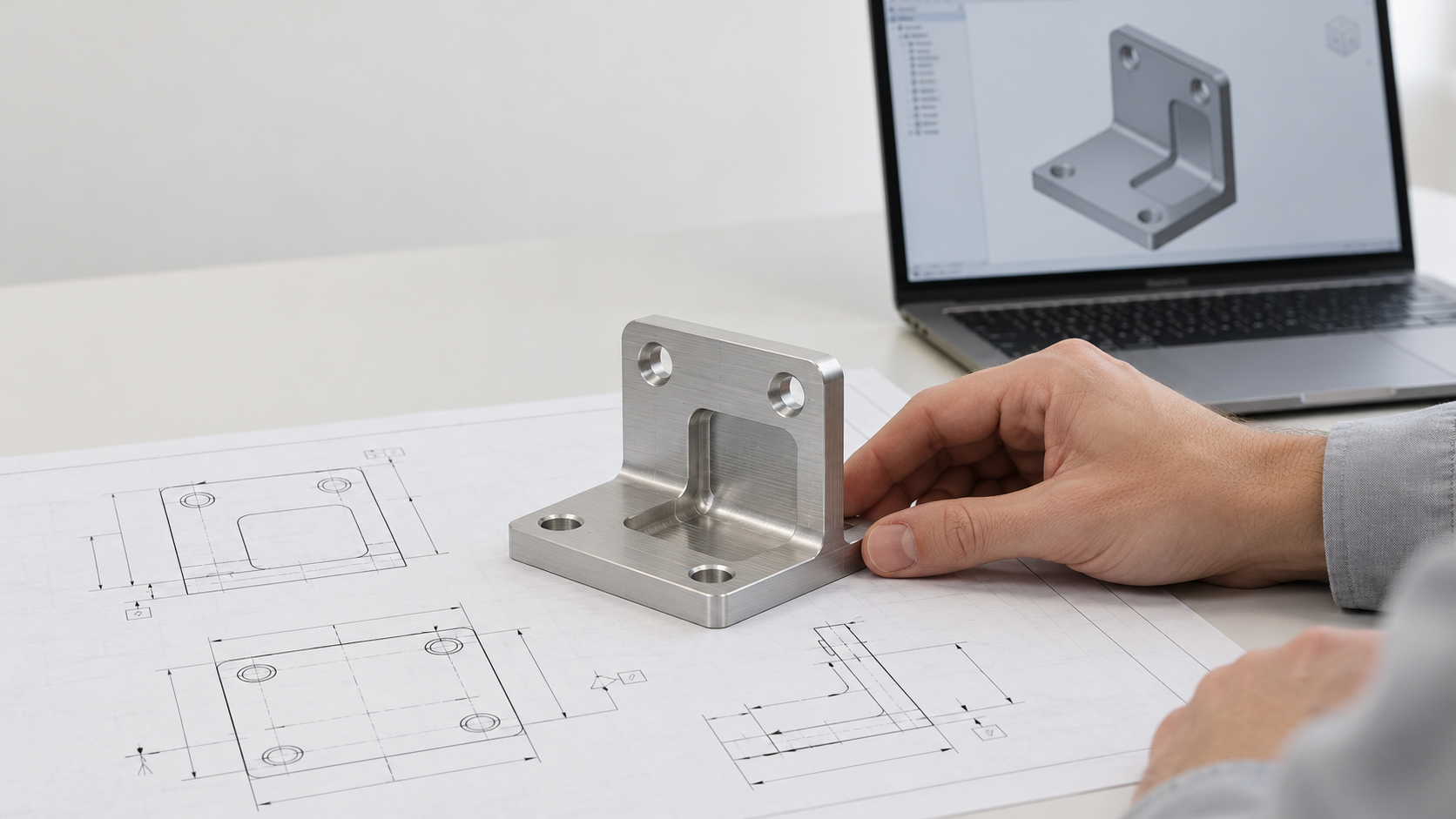
Why Rapid Machining of Small-Batch Metal Parts Is Always “Not Quite Fast Enough”
A project may require only a small quantity of metal brackets, bushings, or mounting bases, yet need to validate the assembly as quickly as possible. When the drawings also include deep cavities, nonstandard holes, multiple tight tolerances, and requirements for a complete inspection report, a supplier's delay in providing a firm quotation is not necessarily because the machine schedule is too slow. More commonly, the reasons are that how the part will be made, which dimensions must be met, and how it will be accepted upon delivery have not been clearly defined.
The lead time for rapid machining of small-batch metal parts typically consists of five waiting periods: quotation waiting, engineering clarification waiting, machining-schedule waiting, post-processing waiting, and inspection-release waiting. Missing 3D models or unclear material conditions can lead to repeated quotation confirmations; thin walls, deep narrow cavities, and difficult-to-access machining surfaces may require special tools, fixturing, and trial cuts; if anodizing, coating, or heat treatment requires outsourcing, delays are shifted to after machining; and if critical dimensions, sampling rules, and report formats are not agreed upon in advance, the parts may still be unable to be released after completion.
Rapid Machining Starts by Reducing Uncertainty, Then Compressing Cutting Time
Therefore, rapid machining is not simply about completing every operation faster; it is about reducing back-and-forth between stages. The procurement or engineering team should first submit usable CAD files, complete 2D drawings, the material grade and condition, quantity, surface treatment, delivery milestones, and critical datums and inspection requirements. Before quoting, the supplier should provide feedback on tool accessibility, fixturing risks, and material or post-processing availability. DFM review addresses “whether the part can be machined consistently,” while a risk-graded inspection plan addresses “how to verify it after completion.” Bringing both forward is the only way to shorten quotation, manufacturing, and acceptance waiting times at the same time.
Rapid Machining RFQ: Prepare a Complete Small-Batch CNC Quotation Package First
When small-batch metal parts require rapid machining, the first thing a supplier needs to determine is not “can it be made?” but whether the material, quantity, geometric features, and acceptance conditions have been clearly defined. Missing information consumes time through repeated clarification, and quoting, scheduling, and inspection may all be forced to pause.
What Documents Should a Rapid Machining RFQ Package Include?
- 3D CAD model: Provide a model that can be opened, with identifiable units and revision information, and specify whether the supplier may propose local design modifications.
- 2D engineering drawing: Identify the material grade and condition, units, general tolerances, critical datums, threads, surface roughness, and deburring requirements. The model cannot replace this acceptance information.
- Quantity and batch: Specify whether the parts are prototypes, a first trial batch, or repeat small-batch production. Changes in quantity can affect fixturing, tool preparation, and production scheduling.
- Surface treatment: Specify anodizing, plating, passivation, blasting, or other post-processing, as well as requirements for color, coating thickness, and appearance acceptance. Post-processing may introduce additional lead time for outsourced operations.
- Delivery and inspection: Provide the delivery address, target milestone, packaging requirements, list of critical dimensions, and whether documents such as a first-article report, dimensional report, or material certificate are required.
Material should not be specified simply as “aluminum” or “stainless steel.” The specific grade, condition, and acceptable substitute materials affect procurement, cutting parameters, deformation risk, and subsequent surface treatment. If the material has not yet been determined, list it separately as an item requiring confirmation in the RFQ rather than leaving the supplier to guess.
Separate functional requirements from process recommendations
The drawing should clearly identify which dimensional relationships directly affect assembly, positioning, or motion, such as shaft diameters, locating holes, mounting surfaces, and true positional relationships; ordinary external dimensions can follow the general tolerances specified on the drawing. Do not apply tight tolerances to the entire drawing, and do not use “precision machining” as a substitute for specific numerical values. Suppliers may provide DFM recommendations regarding tool accessibility, fixturing datums, material substitutions, or surface treatment, but the final functional dimensions, datums, and acceptance criteria should still be confirmed by the design team. An RFQ prepared this way genuinely supports rapid machining instead of deferring uncertainty until the production or delivery stage.
CNC DFM checklist: How thin walls, deep cavities, and hole features can slow rapid machining
Rapid machining of small-batch metal parts is often slowed by thin walls, deep narrow cavities, and difficult-to-access machining surfaces. The problem is not necessarily cutting speed, but whether tool access, fixturing stability, and subsequent inspection can be controlled. During a CNC DFM review, the supplier should confirm each item by asking “Can it be machined, how will it be fixtured, and how will it be measured?” rather than merely checking whether the model can be imported into the software.
Tool accessibility and feature orientation come before machining speed
Deep narrow cavities, small internal radii, and lateral holes may require longer tools or multiple setups. Long tool overhangs are more susceptible to vibration, deflection, and dimensional variation; if the feature orientation is changed and the part must be repositioned, datum-transfer errors will also increase. Where function permits, increase internal radii, reduce unnecessary cavity depth, or arrange critical holes and datum surfaces in directions that allow machining in a more accessible single setup.
Thin walls, deep holes, and threads require risks to be defined in advance
Thin-walled parts may deform under cutting forces, clamping forces, or heat, while deep holes may present challenges with chip evacuation, tool runout, and hole-diameter stability. Nonstandard hole diameters increase the need for special tools or additional operations, and excessively long threads can make tapping, deburring, and measurement more complex. There is no fixed threshold applicable to all materials and equipment; the supplier should confirm the feasible range based on the material, stock condition, tooling, and equipment.
- Thin walls: Confirm the minimum wall thickness, clamping locations, and allowable deformation; if function permits, add support or increase the wall thickness appropriately.
- Holes and threads: Prefer commonly used hole diameters and thread specifications, and specify the effective depth and whether through-hole or blind-hole requirements apply.
- Fixturing datums: Provide flat, locatable datum surfaces and clearly define the positional relationships between critical surfaces.
- Rapid machining quotation: Confirm in advance whether special tools, secondary setups, or dedicated inspection fixtures are required, and whether these operations are included in the quotation and lead time.
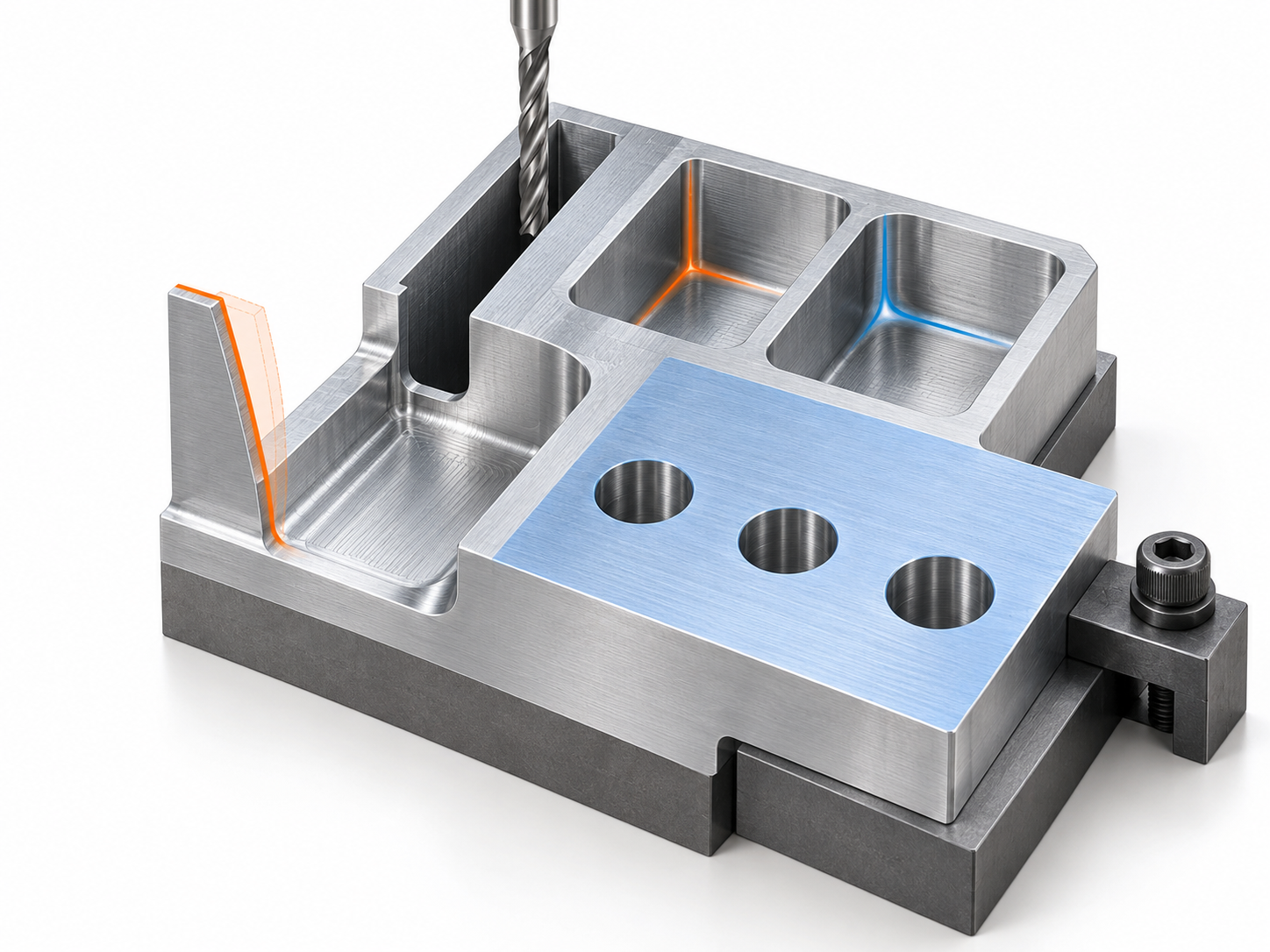
Do not apply tight tolerances to the entire drawing for rapid machining: identify function-critical dimensions first
Rapid machining does not mean eliminating tolerances or reducing inspection; it means allocating resources to the dimensions that genuinely affect function. Functional mating dimensions, assembly datums, locating holes, and interface dimensions should have clearly specified critical tolerances and measurement datums; appearance-related requirements should distinguish between dimensions, burrs, surface roughness, and post-processing condition. Other noncritical dimensions may use reasonable general tolerances, but the final requirements must still be based on the drawing, material, process, and supplier confirmation.
If the datum definition is unclear, or if geometric tolerances such as position, flatness, and concentricity conflict with one another, the supplier will need to repeatedly clarify the fixturing and measurement methods, and inspection results may fail to align. When requesting a quotation, also specify the acceptance priorities for critical features and the applicable inspection fixture or report format. This does not lower quality requirements; it enables CNC rapid machining to organize machining and first-article inspection around functional risks, reducing disputes after delivery.
When machining quickly, should every dimension be assigned a tight tolerance?
Not recommended. Tight tolerances should serve specific functions such as fit, location, sealing, or motion. Reasonable general tolerances can be used for ordinary non-critical dimensions to reduce unnecessary process control and measurement burdens, but they cannot replace drawing requirements or process confirmation with the supplier.
How should first-article inspection be arranged for critical dimensions?
Prioritize features that affect assembly and function, such as mating dimensions, locating holes, shaft diameters, flatness, and positional tolerances. The inspection method should match the tolerance and geometry. Micrometers, height gauges, dedicated inspection fixtures, or coordinate measuring machines may be used; not every dimension requires the same equipment.
Will surface roughness requirements affect the lead time for rapid machining?
Yes. Excessively stringent roughness requirements may add finishing, tool-control, and measurement steps, while post-processing may also introduce additional waiting time. Such requirements should be specified only where sealing, sliding, assembly, or appearance genuinely demands them, and the acceptance method should be confirmed during the quotation stage.
What problems can arise if general tolerances are not clearly specified on the drawing?
Different suppliers may apply different default interpretations, resulting in inconsistent quotation, machining, and acceptance standards. The RFQ should clearly specify general tolerances, critical datums, measurement conditions, and reporting requirements. If a particular standard is used, its scope of applicability should be confirmed rather than simply listing the standard name.
How Material and Process Routes Change Lead Times for Rapid Machining of Metal Parts
There is no universal ranking of material speeds for rapid machining of small-batch metal parts. Lead time first depends on whether a suitable grade, condition, and size of material are available, followed by cutting time. Aluminum alloys, steel, stainless steel, and brass have different machinability characteristics. Even for the same material, bar stock, plate, and near-net-shape blanks can require different material preparation and fixturing plans. During quoting, confirm the material source, condition, whether substitute grades are acceptable, and whether material certification is part of the acceptance requirements.
Rapid Machining Lead Times Start with Material, Blanks, and Post-Processing
Surface treatment often becomes a waiting point after machining is complete. Anodizing, electroplating, passivation, heat treatment, or painting may require outsourcing and can affect dimensional, color, hardness, and appearance acceptance. Before expediting an order, confirm that material inventory, post-processing suppliers, transportation milestones, and inspection resources are aligned. “3–7 days” or “24–48 hours” shown on a supplier’s page should be regarded only as examples under specific material, quantity, geometry, and scheduling conditions, not as direct industry commitments.
Rapid Machining Routes Are Determined by Feature Accessibility
Three-, four-, and five-axis machining do not represent a fixed speed hierarchy. If most of a part’s features can be machined from one direction, three-axis machining with suitable fixturing may be more direct. When multiple sides must maintain positional relationships, four- or five-axis machining may reduce the need for reclamping. A rotational part does not necessarily require turning alone: end-face holes, keyways, eccentric surfaces, or lateral threads may require live tooling or secondary milling after turning. Every additional setup requires re-establishing the datum and entails positioning errors, alignment, and scheduling delays.
- [object Object]
- [object Object]
- [object Object]
- [object Object]
Turning, Milling, and Secondary Operations: Part Geometry Determines the Rapid Machining Route
In rapid machining of small-batch metal parts, an exterior that looks cylindrical does not necessarily indicate a simple process. A basic sleeve can usually be machined as a rotational part by turning. However, once deep holes, internal threads, eccentric holes, keyways, end-face flats, or intersecting holes are added, live tooling, secondary milling, or reclamping may be required. Differences in lead time often depend less on a single cutting operation than on whether tool accessibility, datum changes, and subsequent inspection have been incorporated into the process route.
Turning Parts in Rapid Machining: First Distinguish Rotational Features from Secondary Features
If a part consists primarily of external diameters, internal bores, end faces, and annular grooves, turning is usually the more direct process. The RFQ should specify shaft diameters, bore diameters, concentricity requirements, and which end faces or steps serve as assembly datums. For deep bores and slender holes, further confirmation is needed regarding the depth-to-diameter ratio, chip evacuation conditions, and measurement method. Internal threads also involve the pilot hole, usable thread length, and thread specification; it is not sufficient to retain only a helical surface in the model without specifying the applicable standard.
When a part requires keyways, side holes, flat surfaces, or eccentric features, the supplier may use a mill-turn process with live tooling, or turn the blank first and then perform secondary milling. Neither approach is universally preferable; the key factors are quantity, material, feature orientation, equipment scheduling, and fixturing. Where functionality permits, standardizing the direction of side holes, reducing eccentric features, or enabling critical surfaces to be machined from the same datum will generally help reduce process clarification.
Rapid Milling of Milled Parts: Define Datums and Permitted Secondary Fixturing
For mounting bases, flanges, and parts with holes on multiple faces, what truly affects rapid machining is not whether the equipment is called three-axis, four-axis, or five-axis, but whether the tools can access the features and whether multi-directional positioning is required. Deep cavities, intersecting holes, and concealed side faces may increase the number of setups; each repositioning requires managing datum transformations, fixture interference, and positional relationships between features. Drawings should clearly identify which holes, planes, and axes must meet positional or perpendicularity requirements, and which nonfunctional surfaces may be used as process surfaces.
In the RFQ, ask directly: Can the critical dimensions be completed in a single setup? If a second setup is required, what datum does the supplier use for repositioning? Which surfaces require stock allowance or designated clamping areas? If feature orientations can be changed, reasonable process datums added, or unnecessary concealed machining surfaces converted into accessible surfaces, these changes will often shorten the rapid-machining path more effectively than simply requesting expedited service, where functionality permits. The final process must still be confirmed based on the material, quantity, fixtures, and equipment schedule.
Move Metal Part Inspection Upstream: Control Rapid-Machining Risk with First-Article Inspection
When lead times are tight, rapid machining should not be achieved by eliminating inspection in exchange for a few hours. A more reliable approach is to define the acceptance criteria, measurement methods, and release conditions first, then arrange first-article inspection or batch sampling based on dimensional risk. This can reduce waiting after machining is complete due to inconsistencies in datums, report formats, or surface requirements.
Which Dimensions Must Be Measured First in Rapid Machining
Shaft diameters, bore diameters, locating-hole positions, fit lengths, flatness, and positional accuracy that directly affect assembly should generally be included in first-article measurements; if these features are out of control, the part may be impossible to install even if its appearance is acceptable. Whether critical dimensions require 100% inspection depends on the quantity, functional risk, drawing requirements, and agreement between both parties. General external dimensions or noncritical chamfers may be inspected by agreed batch sampling when the requirements are clearly defined, but sampling inspection cannot replace special acceptance requirements specified on the drawing.
Match Measurement Tools and Reports to the Tolerances in Rapid Machining
Calipers are suitable for quickly verifying general dimensions, while micrometers are better suited to precision measurement of shaft diameters, thicknesses, and similar dimensions. Height gauges, dedicated inspection gauges, or CMMs should be selected based on the datums, positional accuracy, flatness, and feature accessibility. Not every part requires a CMM report; instrument accuracy and measurement methods must match the tolerance zone. When requesting a quotation, confirm in advance whether the report will include actual values, nominal values, tolerances, measurement datums, inspection dates, and part numbers.
- First-Article Scope: Clearly Define the Critical Dimensions, Datums, and Number of Samples to Be Measured.
- Batch Rules: Specify the sampling ratio or quantity and whether the inspection scope will be expanded if any parts fail.
- Appearance and Finishing: Record the evaluation method for burrs, scratches, surface roughness, color, coating, or anodizing condition.
- Nonconformance Handling: Agree in advance on the approver for out-of-tolerance isolation, rework, or concession acceptance to avoid waiting for a decision after the parts are completed.
For small-batch metal parts, it is recommended to send the inspection requirements together with the RFQ rather than adding them before delivery. Once the critical dimensions, sampling rules, and report contents have been defined, the supplier can integrate measurement into the machining process. What rapid machining truly compresses is the waiting time for clarification and rework, not the quality assessment itself.
FAQ: How to Evaluate Rapid Machining, Small-Batch CNC, and First-Article Inspection
Rapid machining should not be evaluated solely by cutting time; part features, material, quantity, functional risk, and acceptance agreements must also be considered. The following questions can be used to verify the process route and RFQ conditions.
Does Rapid Machining of Small-Batch Metal Parts Always Require Five-Axis Machining?
Not necessarily. If three-axis or four-axis equipment can access the primary features and complete the machining through appropriate fixturing, there is no need to select five-axis equipment solely to pursue speed. The value of five-axis machining generally lies in reducing setups, improving tool accessibility, or handling complex features in multiple directions; the choice should be confirmed based on the material, quantity, and production schedule.
Can an Expedited Rapid-Machining Project Skip DFM Review?
Not recommended. When expediting, the DFM review should be shortened rather than eliminated. Issues such as thin walls, deep narrow cavities, nonstandard hole diameters, and difficult-to-clamp datum surfaces may not be discovered until after machining, potentially causing rework or rescheduling and ultimately delaying delivery.
Do all low-volume parts require a full-dimensional CMM report?
Not necessarily. Critical assembly dimensions, positional tolerances, or high-risk datums can be measured on the first article or inspected 100%; ordinary dimensions can be sampled according to mutual agreement. Measurement tools should be matched to the tolerances, features, and acceptance requirements. Calipers, micrometers, height gauges, inspection gauges, or CMMs may all be suitable.
How can you determine whether a rapid machining RFQ is ready for quotation?
At a minimum, it should include a usable 3D model, complete 2D drawings, the material grade and condition, quantity, surface treatment, critical datums and tolerances, thread requirements, inspection report requirements, and delivery milestones. If any of this information is missing, the supplier will typically still need to confirm the process, material, acceptance method, or post-processing arrangements.
Key takeaways
- The lead time for rapid machining is determined collectively by multiple waiting points, including quoting, engineering clarification, machining, post-processing, and inspection.
- Complete 3D models, 2D drawings, material specifications, quantities, surface treatment requirements, and acceptance criteria are the foundation of an effective CNC machining RFQ.
- Thin walls, deep narrow cavities, small internal radii, deep holes, nonstandard hole diameters, and difficult-to-clamp datum surfaces may increase tooling, fixturing, and vibration risks.
- Tight tolerances should be concentrated on function-critical dimensions, assembly datums, and interface locations; noncritical dimensions can use reasonable general tolerances.
- The inspection plan should be established during the RFQ stage: critical assembly dimensions can undergo first-article approval or 100% inspection, while standard dimensions can be batch-sampled according to the agreement.



