What Does a Machining Technology Position Actually Accomplish? Following a Part from Drawing to Qualified Product
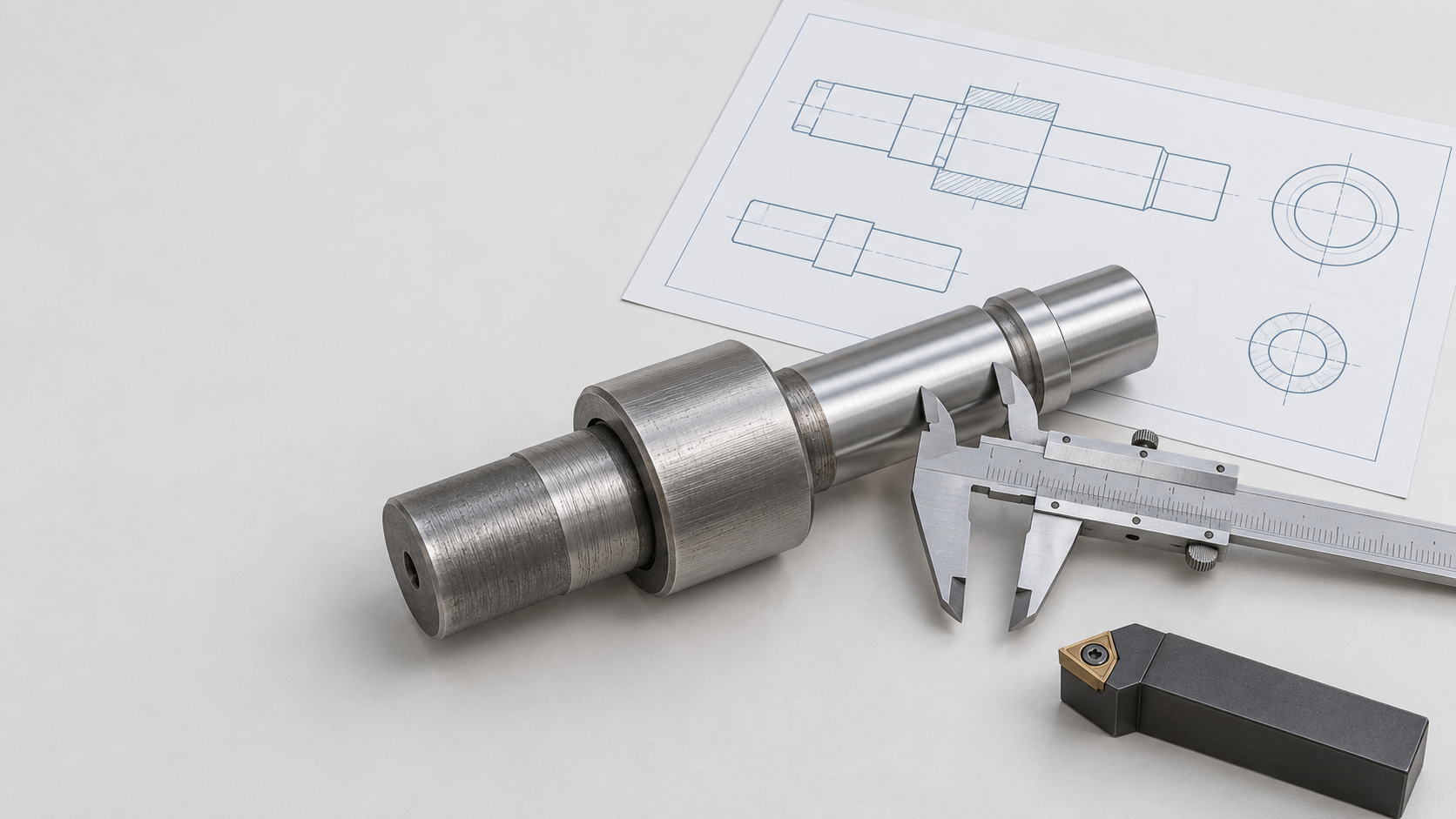
When a metal part drawing featuring an external cylindrical surface, internal bore, groove, and mating surfaces reaches a shop-floor operator, the real question is not “Can they press the machine start button?” but whether they can turn the drawing requirements into a machining task that is executable and verifiable. The material, blank, dimensional tolerances, surface roughness, and technical requirements all affect the machining sequence, workholding method, tool selection, and final measurement.
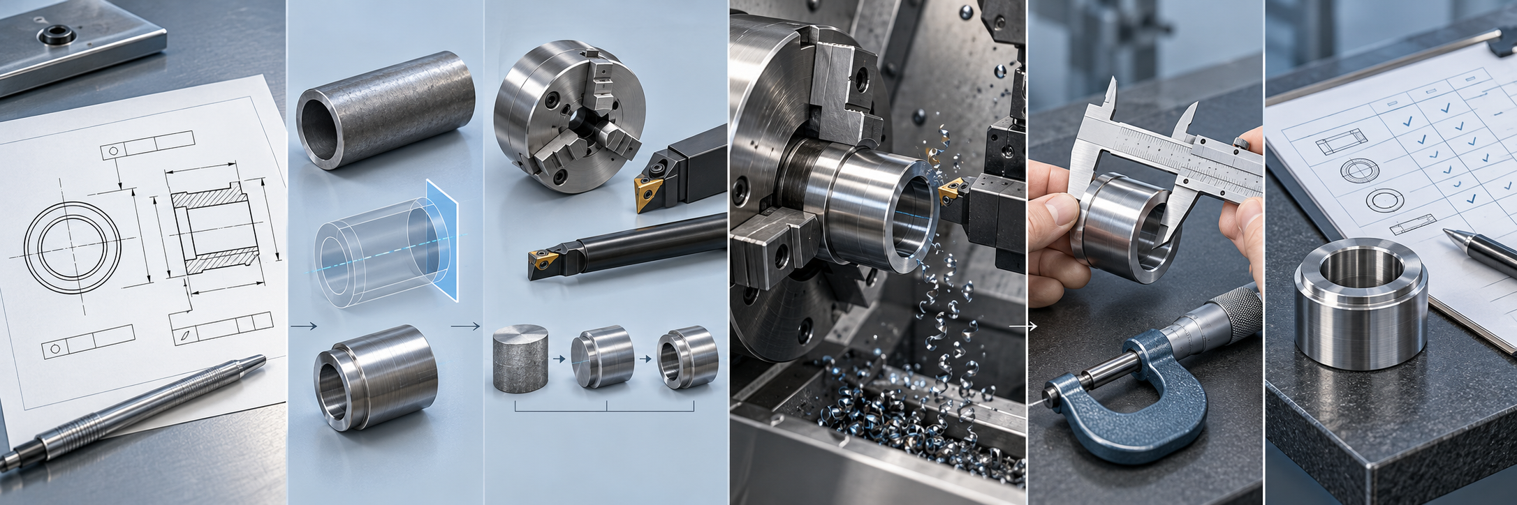
Therefore, machining technology is not a set of isolated courses, but a workflow extending from design requirements to the determination of a qualified product. The operator first interprets the part drawing and assembly relationships, then analyzes the structure and machining challenges; next, they prepare the process plan and select the machine tool, fixture, cutting tools, and measuring instruments. During CNC machining, the process intent is converted into a program, and the results are verified through simulation, machine operation, and first-piece measurement. If dimensional or geometric requirements are not met, the operator must trace the issue back to workholding, tool wear, parameters, or measurement methods, and provide feedback to the process or shop-floor operations.
What to Learn First in Machining Technology: Turning Part Drawings, Assembly Drawings, and Technical Requirements into Machining Tasks
The starting point of machining technology is not pressing the machine start button, but understanding the drawings. When presented with a drawing of a shaft sleeve or flange-type part, the operator must first confirm the material, blank form, and primary features, then identify the locating datums, critical dimensions, holes, grooves, threads, and mating surfaces. A part drawing explains “what shape and condition a single part must be machined to,” while an assembly drawing helps determine how it connects, moves, or mates with adjacent parts.
Drawing interpretation cannot be limited to reading nominal dimensions. Dimensional tolerances determine the permitted range of variation, and fit requirements affect how external diameters, internal bores, or shoulders are machined and measured. Geometric requirements may change the workholding datums and machining sequence, while surface roughness requirements indicate that tools, cutting conditions, and subsequent treatments cannot be arranged arbitrarily. The technical requirements on the drawing must ultimately be converted into specific machining actions and inspection items.
In machining technology, drawing interpretation must support on-site decisions
Take a shaft sleeve with an internal bore and end face as an example. The learner should be able to record which surface is suitable as a locating datum, whether the bore and external diameter have a mating relationship, whether the end face has a perpendicularity requirement relative to the axis, and which dimensions require focused measurement during first-piece inspection and final inspection. If someone can only say “I understand the drawing” but cannot identify the workholding datum, machining priorities, and measurement methods, they have not yet converted mechanical drafting into job competency.
- Identify: Read the material, structure, datums, dimensions, tolerances, and surface requirements.
- Judgment: Analyze the impact of these requirements on workholding, machining sequence, and tool accessibility.
- Record: Organize the key dimensions and inspection items to provide a basis for subsequent process planning and quality determination.
What to Learn in Machining Process Design: From Datum Selection to Tools, Fixtures, and Machining Parameters
If a drawing explains “what requirements the part must meet,” machining process design addresses “how to produce it consistently.” After receiving a part drawing, you cannot begin programming or machining immediately. You must first assess the material, blank shape, critical surfaces, machining allowance, and dimensional tolerances, and then convert the design requirements into an executable machining route.
Datums and Operation Planning in Machining Technology
Process engineers must first select the locating datums and determine how the part will be clamped, which surfaces should be machined first, and where subsequent dimensions will be established. A common approach is to first machine the datum surfaces or datum holes used for positioning, followed by roughing, semi-finishing, and finishing to remove the allowance progressively. For shaft-sleeve parts, the external diameter and end face may be processed first, followed by the internal bore. For parts with hole patterns or cavities, particular attention must be paid to datum consistency, hole-to-hole relationships, and tool accessibility.
How to Match Equipment, Tools, and Fixtures in Machining Processes
The next step is to determine whether a lathe, milling machine, or machining center is suitable for the part, and to select the fixtures, cutting tools, measuring instruments, and cutting parameters. The fixture must ensure reliable positioning and sufficient clamping rigidity while avoiding obstruction of the machining area. The tool must meet the requirements for structural accessibility and material machinability. Parameters must be adjusted based on the condition of the equipment, tool specifications, material, and machining allowance rather than copied from fixed values. Thin-walled, slender, or highly overhanging structures also require consideration of vibration, deformation, and repeat clamping errors.
A qualified process plan should contain more than just operation names. It should also include the machining sequence, positioning and clamping method, tool and measuring instrument selection, key parameters, and quality control points. The subsequent CNC program must follow this process plan. When learning machining technology, you can practice with a typical part: first draw the datums and operation route, then explain the machining objective of each operation, and finally list the dimensions that require priority measurement on the first article. Only in this way can drawing requirements be truly converted into shop-floor actions.
What to Learn in CNC Machining Technology: Programming, Simulation, Machine Operation, and First-Article Verification
CNC machining technology is not about learning to enter programs first; it begins with understanding the process. Once process personnel have determined the machining sequence, locating datums, work coordinate system, tools, and cutting paths, operators can convert these requirements into a CNC program. Lathes mainly process rotational surfaces such as external diameters, internal bores, end faces, and threads, while milling machines or machining centers are more commonly used for planes, slots, hole patterns, and cavities. Different equipment involves different coordinate directions, clamping methods, and program-checking priorities.
After programming is completed, simulation is required to check the tool path, approach and retract positions, machining sequence, and dimensional logic, so that potential risks such as overcutting, air cutting, or collisions can be identified in advance. However, simulation cannot replace on-site verification. Before formal machining, the equipment condition, fixture tightness, and tool installation and wear must still be checked. Tool setting and workpiece coordinate setup must be completed correctly, followed by dry running, trial cutting, or other low-risk verification in accordance with the equipment operating procedures.
After the first article is machined, key dimensions, hole positions, mating surfaces, and other technical features must be measured according to the part drawing and inspection requirements to determine whether the program and process are truly effective. If the first article has dimensional deviations, do not simply modify program values; also investigate tool compensation, clamping deformation, datum selection, and equipment condition. Thus, CNC capability in machining technology must ultimately be demonstrated by the ability to program according to the process, operate safely, verify results, and provide feedback on problems—not merely by knowing how to use a particular software package or CNC system.
How Quality Inspection Integrates into the Machining Process: Measuring Instrument Selection, Dimensional Acceptance, and Deviation Feedback
In machining technology roles, quality inspection is not an isolated task performed only after part machining is complete. Instead, it is a continuous closed loop extending from drawing interpretation, datum determination, clamping, and machining through final measurement. Inspectors must first return to the part drawing, technical agreement, and inspection specification to confirm the dimensions, tolerances, geometric requirements, surface roughness, and fit relationships that need to be controlled, and then determine the measurement methods and recording procedures.
Measuring Instrument Selection and Measurement Datums in Machining Technology
Measuring instruments should not be selected simply based on “whatever is at hand.” External dimensions may be measured with calipers or micrometers as required, while bore diameters may require internal measuring tools, bore gauges, or other suitable instruments. When geometric requirements such as coaxiality or perpendicularity are involved, the establishment of datums and the suitability of dedicated gauges and measuring equipment must also be considered. For shaft-sleeve parts, for example, the relationship between the external diameter, internal bore, and end face is often more important than measuring a single diameter in isolation. During measurement, the same datums as those on the drawing should be maintained to avoid misjudgment caused by different locating methods.
Result Evaluation and Deviation Feedback in Machining Technology
Inspection results should be recorded in a traceable manner and compared item by item with the drawing requirements. There are no universal values for coaxiality, fit dimensions, or surface roughness that apply to all shaft sleeves. The specific acceptance range depends on the part drawing, material, machining process, technical agreement, and inspection specification. If a dimension is out of tolerance, it is necessary to further distinguish among measurement error, tool wear, changes in fixture location, clamping deformation, and unsuitable machining parameters rather than simply classifying the issue as an “operator error.”
For example, a bore that gradually becomes larger may be related to tool wear or compensation settings, while abnormal coaxiality should prompt checks of datum transfer, clamping rigidity, and machining sequence. The output of quality inspection should be more than simply “accepted” or “rejected.” Deviations should also be fed back to the process planning, programming, and equipment operation stages for adjustment of tools, fixtures, parameters, or operation sequencing. Only the ability to complete measurement, evaluation, recording, and feedback constitutes true mastery of the quality loop in machining technology.
What Else Does Machining Technology Include: Equipment Maintenance, Safe Operation, and On-Site Communication
Being able to write CNC programs does not mean that one has comprehensive machining technology skills. Before loading a program into the machine tool, operators must also confirm that the equipment condition, fixture installation, tool wear, and workpiece clamping meet process requirements. Equipment, control systems, and job responsibilities may vary among companies, but following equipment operating procedures is a common requirement.
Equipment Inspection and Safe Operation in Machining Technology
Before starting the machine, check the lubrication, coolant, air lines, emergency-stop device, and guarding; clean the work area; and confirm that the workpiece and fixture are secure. During machining, monitor for abnormal vibration, unusual noises, temperature increases, chip formation, and tool wear. If there is a risk of tool collision, fixture displacement, or rapid dimensional drift, pause the equipment according to the operating procedures rather than continuing to run the program. Equipment maintenance records, tool replacement records, and records of abnormal conditions are all important references for subsequent troubleshooting.
Machining Technology Also Requires Clear Information Handoffs
After machining the first piece, the operator should cooperate with inspection personnel to confirm critical dimensions and record the program version used, tool condition, and measurement results. If a dimensional deviation is found, it should be noted which operation produced the deviation, what clamping method was used, and whether the tool had been replaced, so that process or quality personnel can determine the cause. Drawing revisions, process parameter adjustments, and inspection conclusions should also be communicated promptly to prevent outdated documents from continuing to be used on the shop floor. It is therefore clear that machining technology is not merely “knowing how to start the machine”; it also includes safe execution, equipment maintenance, recordkeeping, and cross-functional communication.
How Beginners Should Structure Their Machining Technology Learning: From Fundamentals to Practical Training with Typical Parts
When learning machining technology, it is not advisable to start by memorizing programming commands or operating machine-tool buttons. A more reliable path is to follow the process by which a part goes from a drawing to an acceptable finished product, gradually developing the abilities to “understand, produce, measure accurately, and review.” Equipment, CNC systems, and job responsibilities vary among companies, so the learning focus should also be adjusted to the target position.
Five Self-Checks for Machining Technology
You can use an unmachined part drawing to assess your learning: Can you extract the critical dimensions and technical requirements? Can you develop a reasonable machining route? Can you explain the choices of locating and clamping method, tools, and equipment? Can you complete program simulation and explain the steps for verification on the actual machine? Can you determine whether measurement results meet the requirements based on the drawing and inspection criteria? Only when all five questions can be answered with specific processes and records can you be considered to have progressed from “having taken the courses” to possessing basic job competence.
Common Questions About Learning Machining Technology
Learning machining technology is not simply about memorizing course names; it is about gradually establishing a work chain from drawing interpretation, process planning, and programming to machining and inspection. The following questions can help check whether the key learning points have been correctly understood.
When learning machining technology, is it necessary to learn CNC programming first?
It is not necessary to make CNC programming the starting point. First master mechanical drafting, materials and the fundamentals of manufacturing, fits and tolerances, and technical measurement, then learn process planning and programming. Without a foundation in drawings and processes, even a program that runs successfully makes it difficult to determine whether the machining sequence, tool selection, and results meet requirements.
Which is more important, drawing interpretation or process planning?
They have a sequential relationship and cannot be simply compared. Drawing interpretation identifies the material, datums, dimensional tolerances, geometrical requirements, and surface quality. Process planning converts these requirements into a locating method, clamping method, machining sequence, tool selection, and equipment plan. If the drawing is misunderstood, the subsequent process plan and program will lose their basis.
Can CNC simulation replace verification on the actual machine?
No. Simulation can help check the toolpath, coordinate logic, and some collision risks, but it cannot replace equipment-condition confirmation, tool and fixture checks, safe on-site operation, or first-piece measurement. Actual machining must still be verified in conjunction with the specific machine tool, clamping method, tool condition, and drawing requirements.
How can you determine whether you have truly learned machining inspection?
You can use a complete part drawing for self-assessment: Can you identify the critical dimensions and datums? Can you select suitable measuring instruments for different requirements? Can you correctly establish the measurement datum? Can you record and evaluate dimensional, geometrical, or surface-quality results? Can you also trace deviations back to the tool, fixture, parameters, or process step?
Are the competency requirements for mechanical machining positions the same across different companies?
Not entirely. A company’s equipment types, CNC systems, product materials, production volume, and division of responsibilities all affect the specific requirements. Some positions focus on equipment operation, while others emphasize process programming or quality control. Therefore, foundational competencies should cover drawing interpretation, process planning, operation, and inspection, with specialized skills added based on the actual equipment and products.
Key takeaways
- The starting point of machining technology is understanding part drawings, assembly drawings, and technical requirements—not learning to press machine-tool buttons first.
- Process planning determines the datums, machining sequence, workholding, tools, and parameters, after which CNC programming converts the process intent into a machine-tool program.
- Equipment operation requires a simultaneous understanding of machine status, tool wear, fixture stability, machining safety, and first-piece verification.
- Quality inspection runs throughout drawing interpretation, workholding, machining, and measurement, and the results should be fed back into the process and shop-floor operations.
- Learning can progress step by step through mechanical drafting and CAD, tolerance measurement, fundamentals of manufacturing, machine-tool operation, CNC programming, hands-on machining, and quality control.



