Starting from an overlay error budget
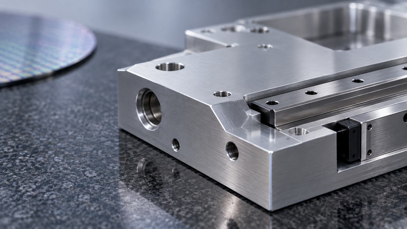
In a wafer fab, what the lithography process fears most is not that a certain layer's pattern is not drawn finely enough, but that this layer and the previous layer are not aligned. The relative offset between two layers of patterns is called overlay error in the industry. It has a total budget, and this budget is not set arbitrarily, but derived backward from device structure, electrical performance, and final yield. Once the budget is determined, it is broken down into several items: the positioning error of the lithography machine itself, the synchronization error of the mask stage, the movement error of the wafer stage, the deformation of the silicon wafer itself, and the geometric deviations brought by the mechanical parts carrying these components.
The key point is that this budget is a whole. Each item that is broken out can only receive a very small share, and any item that overspends will directly eat into the space of the other items, ultimately reflected as a decline in yield. So when a designer says a certain part must be made "very accurate," he usually does not subjectively prefer high precision, but is forced into it by the upstream system budget. The precision index of a part is essentially a downstream product of system error allocation.
Understanding this is very important for people doing machining and procurement. Because it means: talking about "this part needs to be within a few microns" outside the system context is often meaningless. The same part, mounted on a short-stroke mechanism versus a long-stroke mechanism, may have completely different requirements. What really needs to be clarified is: what function does it serve in the system, how will errors be transmitted, and which surfaces are functional surfaces. The answers to these questions determine the machining plan and inspection plan.
The following main thread will run through the entire article: the precision requirements for semiconductor parts can be derived, rather than being an industry habit or aesthetic preference. The starting point of the derivation is the error budget; the derivation process involves how errors stack, how the environment interferes, and how metrics are combined, finally landing on process selection and inspection acceptance. Once this chain is fully understood, many seemingly harsh requirements become discussable and negotiable, rather than something that can only be passively accepted.
How errors are added up: additive logic and amplification effects
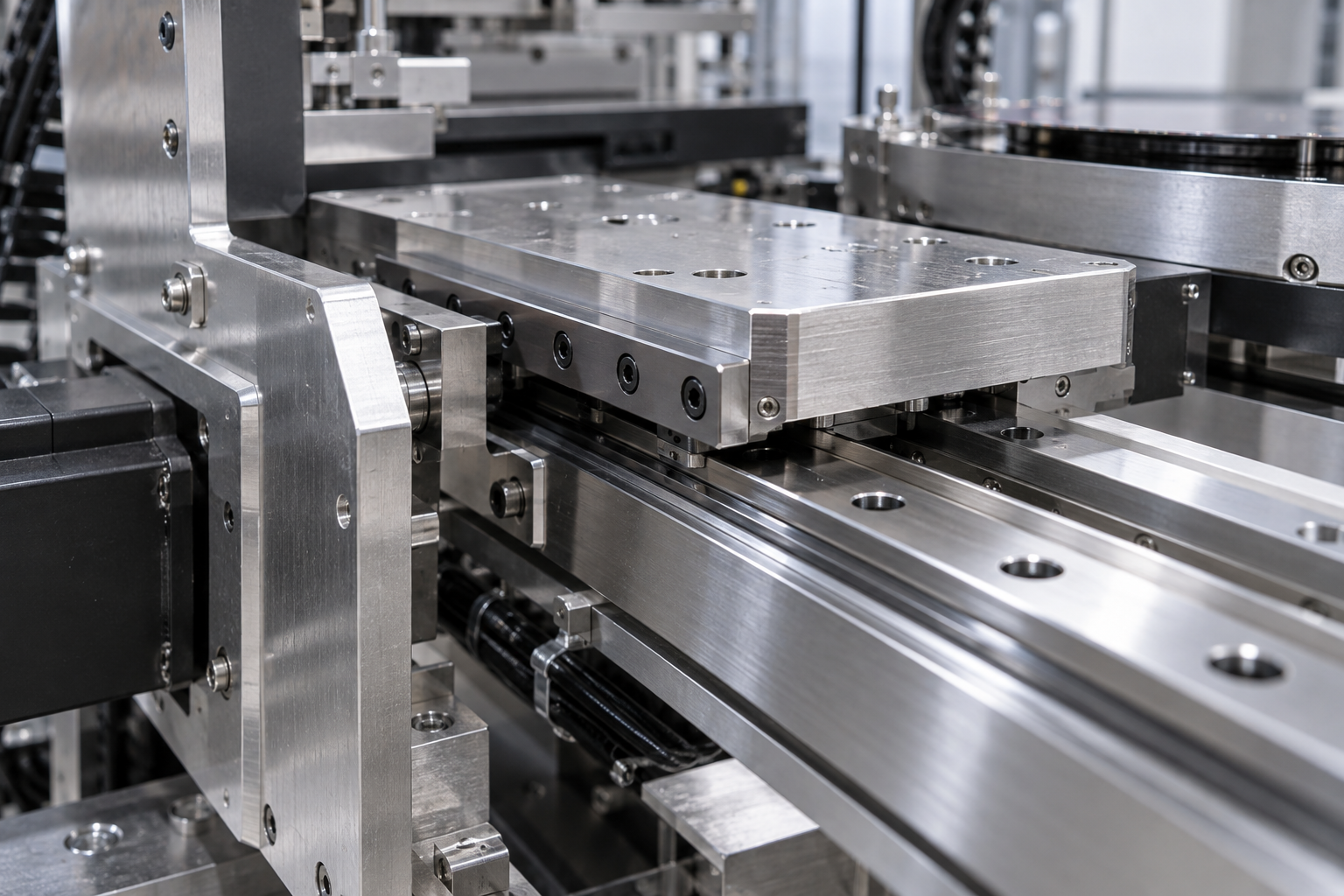
In semiconductor equipment, the dimensional deviation of a part itself rarely determines success or failure on its own. What truly determines success or failure is: after this deviation enters the whole machine, which errors it stacks with, by what mechanism it is amplified, and how much positional offset it ultimately produces on the wafer. So the precision requirement is never "this part looks like it must be very accurate," but "how much error is this part allowed to contribute." Only by understanding this can one understand why some parts are required to the limit while others can actually be relaxed.
The additive structure of the error budget
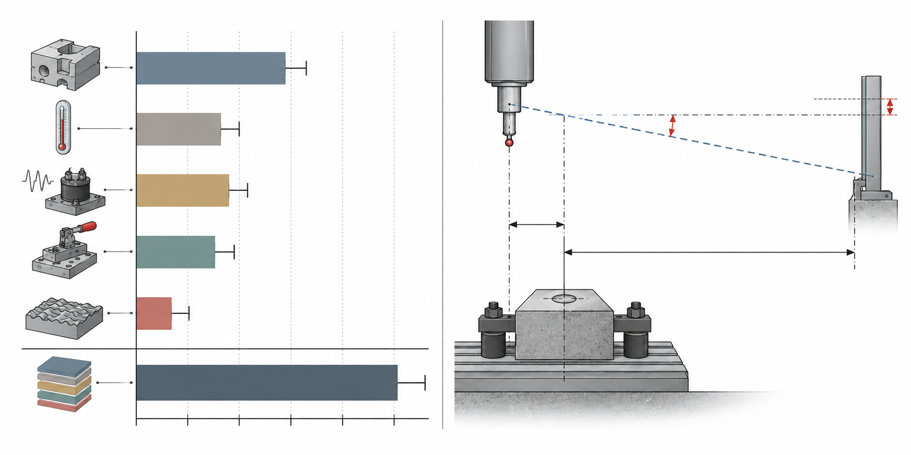
Looking at the whole-machine error budget in breakdown, it usually includes several categories of sources: static geometric errors (guide rail straightness, mounting surface flatness, hole position deviation), thermal deformation (expansion and drift caused by temperature gradients), vibration and dynamic response (structural stiffness, damping, drive reaction forces), fixturing and repeat positioning errors (position consistency after each assembly or wafer change), and contact and measurement deviations caused by surface topography. They are not independent of one another, but at the budget stage they are usually first added under worst-case conditions:
Total error ≈ static geometric error + thermal drift + dynamic error + fixturing repeatability + surface topography contribution
This formula is qualitative, but it illustrates a key fact: every item is competing for the same budget. If thermal drift takes up a large share, the tolerance left for machining is forced to tighten; conversely, if structural design and temperature control are done well, mechanical parts can actually be relaxed. This is also why suppliers are often asked to "first clarify what function this part serves in the whole machine," rather than being asked directly "how much can you achieve."
Abbe error and cosine error: how small deviations are amplified
There are mainly two types of amplification effects. The first is Abbe error: when the measurement axis and the motion axis do not coincide and there is an offset distance, angular deviation is amplified by this distance. The larger the offset, the greater the displacement produced at the end by the same angular deviation. The second is cosine error: when there is a tiny angle between the motion direction and the ideal direction, the actual displacement is shortened relative to the ideal displacement according to a cosine relationship; the larger the angle, the more obvious the position deviation.
These two mechanisms explain why "tiny deviations on small parts" are amplified at the end of long-stroke mechanisms. A tiny tilt of a mounting surface is almost invisible in a short stroke, but after being transmitted through a long arm or long guide rail, the positional offset at the end may already exceed the budget. Therefore, the key parts in semiconductor equipment are often not "the hardest to make dimensionally," but "the hardest to stabilize in terms of angles and datum relationships."
In actual work, the engineering side usually allocates the budget by functional surface: which surfaces determine alignment, which surfaces only determine support, and which surfaces only affect airflow or cleanliness. Functional surfaces are tightened first, and non-functional surfaces are allowed to be relaxed. The result is that precision requirements for different parts in the same piece of equipment can differ greatly, rather than all parts leaning toward the highest precision. If such judgments need to be translated into specific process routes, you can start by comparing the applicable scope of CNC machining capabilities.
Vacuum, heat, and cleanliness: three environmental constraints that change the rules of the game
Many parts measure perfectly fine in an atmospheric workshop, but "deform" after being installed in semiconductor equipment. The problem is often not in the machining itself, but in the environment redefining what was originally a dimensional tolerance issue into a question of materials, surfaces, and long-term stability. The three constraints of vacuum, heat, and cleanliness almost always act on the same part simultaneously, and if any one is ignored, all the prior precision work may be wasted.
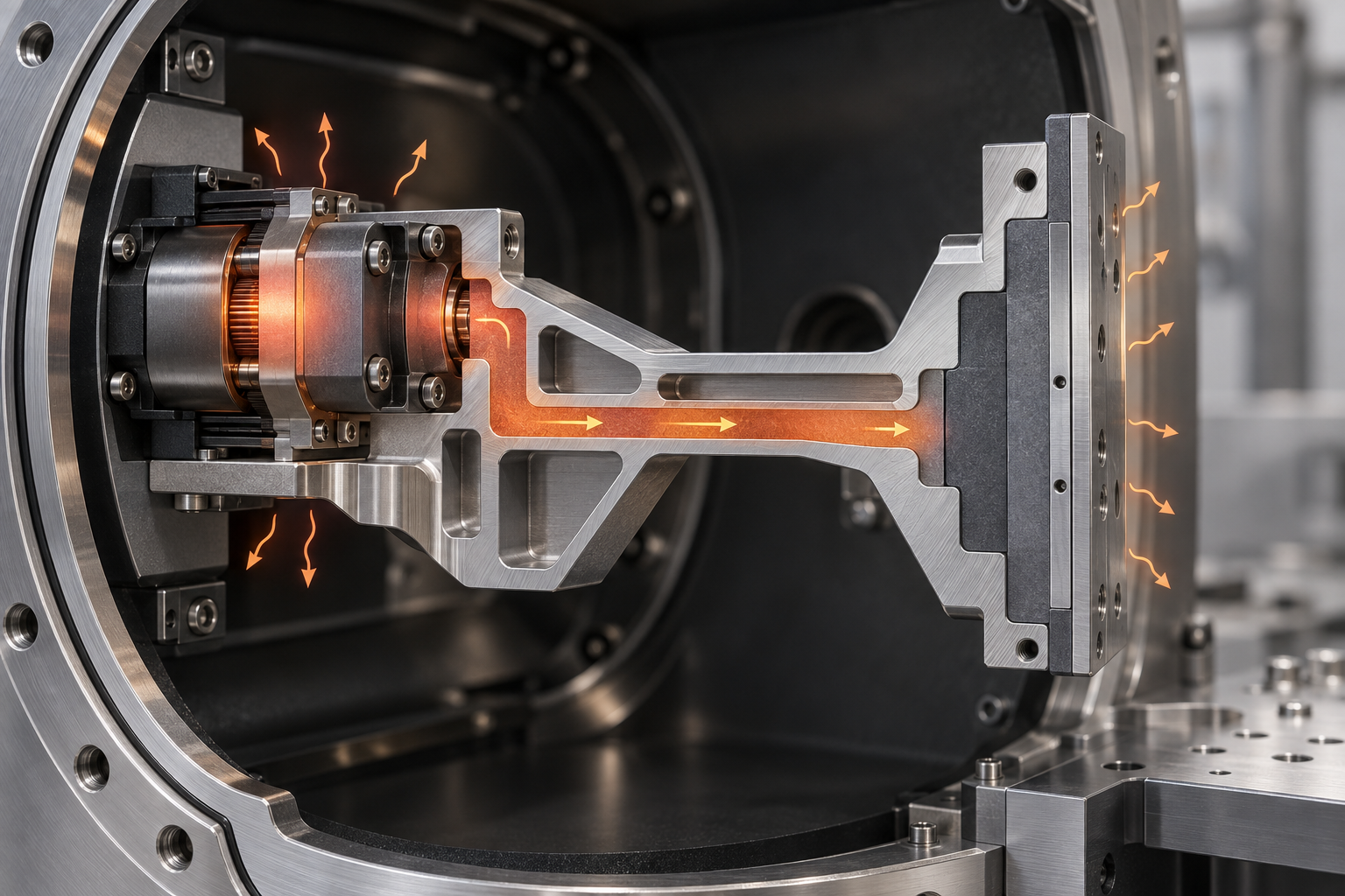
There is no convection in vacuum, so heat can only dissipate through conduction and radiation
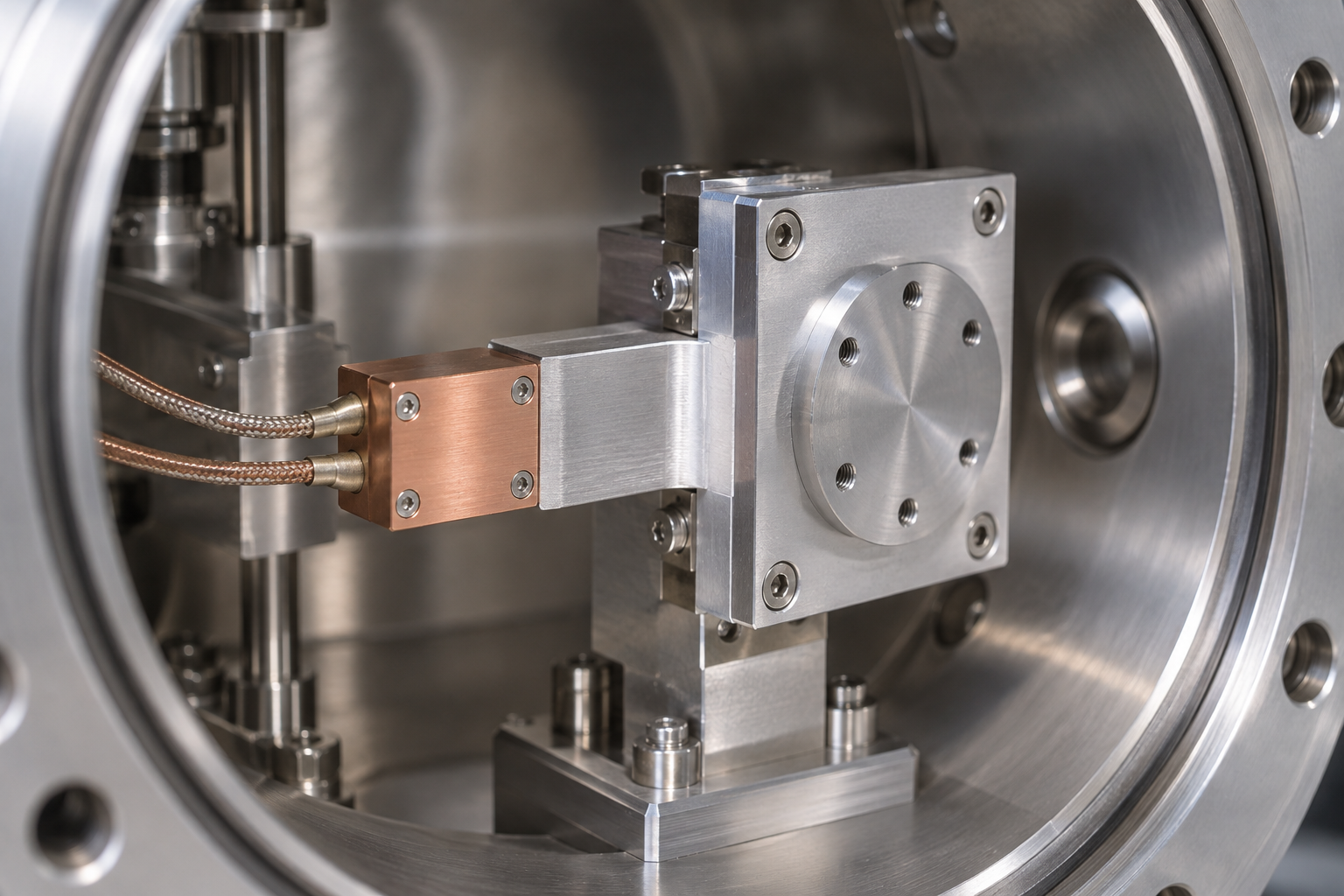
Under atmospheric pressure, most of the heat generated by moving parts and motors is carried away by air convection. After entering vacuum, this convection path basically disappears, and heat can only be dissipated through solid conduction and radiation. The result is: for the same amount of heat generation, a higher local temperature rise will occur in vacuum, and temperature rise directly translates into thermal expansion displacement.
The implication for parts is: thermal management design must be moved forward to the structural parts themselves. For example, make the heat conduction path between the heat source and key functional surfaces short and thick; use low-expansion materials for locations sensitive to displacement; and reserve room for thermal compensation at the assembly level, rather than expecting that "machining accurately enough" can withstand thermal drift. Thermal drift is a systematic error and cannot be eliminated simply by tightening dimensional tolerances.
Vacuum compatibility: materials and lubrication are re-screened
The vacuum environment imposes additional requirements on materials. Ordinary grease may volatilize, and the volatiles may redeposit onto optical surfaces or wafer surfaces; certain plastics and adhesives will continuously outgas and contaminate the chamber. Therefore, parts on the vacuum side usually need to have their materials and lubrication schemes reselected. Common approaches are to switch to dry film lubrication, solid lubrication, or directly use self-lubricating materials, and to avoid seals and adhesives containing volatile components.
This brings a chain reaction that is easily underestimated: when the material is changed, machinability and coefficient of thermal expansion also change. For fits originally designed for aluminum alloy, after switching to a low-expansion material, cutting characteristics, residual stress, and dimensional stability all need to be reevaluated. Material selection is therefore not a finishing action in the procurement stage, but the starting point of the precision chain. For the specific matching of materials and lubrication, it is recommended to confirm with the engineering side already at the drawing review stage.
Cleanliness: hard constraints of particles, outgassing, and surface treatment
In scenarios with high cleanliness requirements, particles themselves are a source of defects. Burrs on part surfaces, machining residue, coating flaking, and debris in threads can all become contamination sources. Therefore, surface treatment is not just a matter of appearance or corrosion protection, but part of cleanliness control: deburring, passivation, cleaning, and packaging methods need to be specified as a whole.
Outgassing is more related to material and surface condition. Porous surfaces, rough surfaces, and residual oil films all increase the risk of outgassing. This means that surface roughness here is not only a fit or friction indicator, but also a cleanliness indicator. When drawings only specify dimensional tolerances and do not define surface condition and cleaning requirements, it is difficult for suppliers to judge what level should be achieved, and disputes are likely to arise in final acceptance.
Precision is not a single number: dimensions, geometry, surface, and stability
The most common misunderstanding between procurement and engineering is treating “precision” as a single number that can be filled into a table. The drawing says ±0.01 mm, the supplier quotes a price, and both sides think it has been made clear. But what really determines whether a part can fit into the equipment and survive a maintenance cycle in vacuum is never that one number, but a set of mutually constraining indicators: dimensional tolerances, geometric tolerances, surface roughness, residual stress, and the stability of these quantities under the effects of time, temperature, and assembly force.
Take a common example from the shop floor. An aluminum support block has all dimensions within the tolerance band, and the inspection report looks good, but after it is installed on the mechanism, the mating face does not fit well, and once the bolts are tightened, the part warps in a way that is invisible to the naked eye. The problem is not the dimensions, but flatness and datum definition. Dimensional tolerances govern “whether the distance between two points is correct,” while geometric tolerances govern “whether this face is still a face.” The former passes, the latter is out of tolerance, and assembly still fails.
What each of the four categories of indicators governs
- Dimensional tolerances: control the nominal deviation of features such as length, hole diameter, and slot width. They are the easiest to measure and the easiest to overemphasize.
- Geometric tolerances: control flatness, parallelism, perpendicularity, coaxiality, position, etc. They determine whether the part can be correctly positioned during assembly and are often more critical than dimensions.
- Surface roughness and topography: affect sealing, friction, outgassing, cleaning difficulty, and optical/contact performance. Surfaces with the same Ra value but different machining texture directions may perform completely differently.
- Residual stress and long-term stability: internal stresses from cutting, welding, heat treatment, or additive manufacturing will be slowly released during subsequent machining or use, causing the part to “deform by itself.” Such problems cannot be detected at delivery, but are exposed after several months of use.
Looking at these four categories together reveals a pattern: dimensions are the item most easily satisfied and also most easily misjudged. The root causes of many rework cases and field failures lie in geometry, surface, or stability, but are masked by a “dimensions pass” report.
Datums and functional faces are more worth discussing first than tightening tolerances
When assembly problems occur, the first reaction is often to “tighten the tolerance a bit more.” But in most cases, the more effective approach is to answer two questions first: Which is the functional face of this part? How is the datum defined?
If the drawing does not specify a datum clearly, the machining side can only choose its own fixturing and measurement datums. When the machining datum, measurement datum, and assembly datum are inconsistent, assembly may still fail even if every dimension is within tolerance. Conversely, if the datum is clear and the functional faces are well defined, many non-functional dimensions can actually be relaxed, reducing cost while making assembly performance more stable.
This is also why, during quoting and DFM, the engineering side prefers to discuss “is this face a mating face or a clearance face” and “is this hole a locating hole or a through hole,” rather than directly discussing tolerance numbers. The position tolerance of locating holes and the flatness of mating faces are usually worth investing in; clearance faces and outer contours can often be moderately relaxed. Spending the precision budget on functional faces is a more rational strategy than tightening everything across the board.
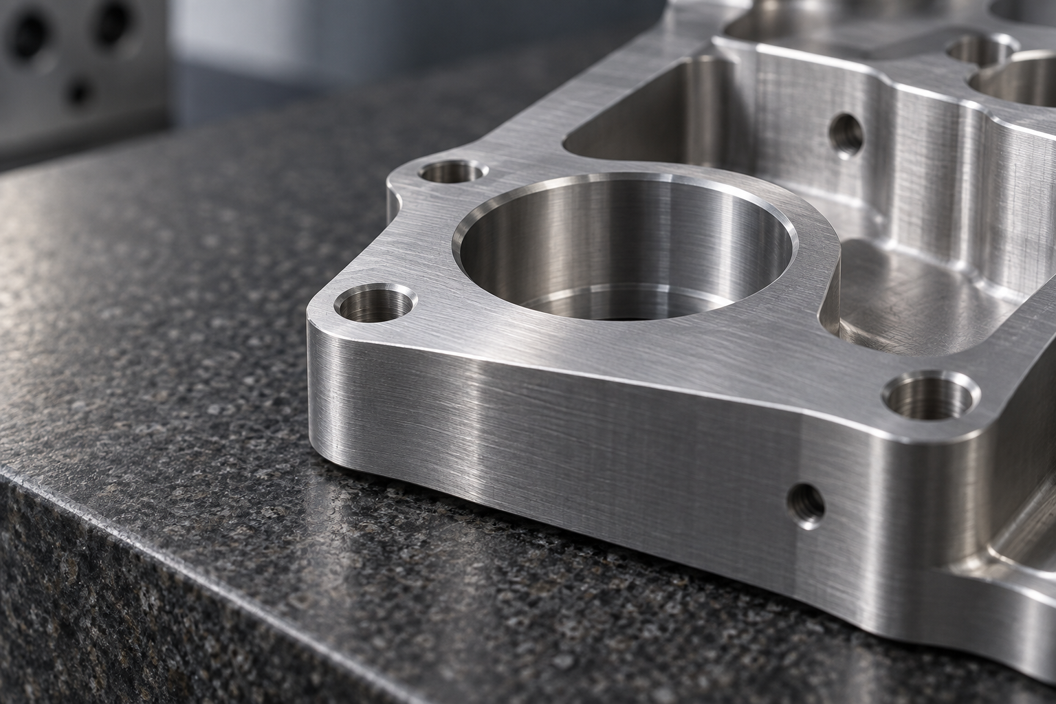
So when someone asks, “What precision requirement does this part need?”, the more accurate answer should be a set of constraints: which faces are functional faces, how the datum is set, whether the surface condition affects outgassing or sealing, and what temperature and load the part will experience during assembly and use. Once these are made clear, the precision requirement becomes a result that can be derived, verified, and negotiated, rather than a number pulled out of thin air.
How to choose the process: the boundaries of CNC, sheet metal, vacuum casting, and additive manufacturing
Once the precision requirements have been derived, the next question is not “who can make it most accurately,” but “which process route should this part take.” Parts in semiconductor equipment vary widely: some are load-bearing structural parts, some are flanges on vacuum chambers, some are flow channel blocks in gas lines, and others are equipment enclosures and cable tray brackets. Forcing these parts into the same process is usually both expensive and unreasonable.
Functional faces determine the route, not the precision number
When judging the route, ask three questions first: Which faces participate in locating and mating? What load and temperature does the part withstand? How will it be assembled and disassembled later? Mating faces, sealing faces, and guide rail mounting faces that participate in locating usually require CNC machining to ensure geometric relationships and surface quality; while panels that only serve for covering, support, or cable routing are often more economical with sheet metal fabrication through bending and welding, and are also easier to lightweight and modify later.
The small-batch transition stage is another typical scenario. The equipment is still being validated and the structure may still need changes. At this time, using vacuum casting for prototype replication to make dozens of appearance parts or non-load-bearing parts can provide parts with a feel close to mass production without opening a steel mold; once the structure is frozen and volume increases, then consider injection molding. Conversely, if the part has complex internal channels, lattice lightweight structures, or integrated topology shapes, traditional subtractive manufacturing is difficult to cut, and 3D printing is instead a more direct path.
| Part feature | Preferred route | Main reason |
|---|---|---|
| Precision mating faces, guide rail seats, sealing flanges | CNC machining | Geometric relationships are controllable, and surface quality facilitates sealing and mating |
| Equipment enclosures, cable trays, mounting brackets | Sheet metal fabrication | High efficiency in bending and welding, easy to lightweight and revise |
| Small-batch appearance parts during validation | Vacuum casting | No steel mold required, close to mass-production feel, low revision cost |
| Complex flow channels, lightweight integrated structures | 3D printing | Internal features that are difficult to form by subtractive manufacturing can be formed in one piece |
| Mass-produced plastic parts after the structure is frozen | Injection molding | Unit cost decreases with volume, with stable consistency |
It should be noted that process boundaries are not absolute. A part often requires a combined route: the main body is CNC machined to create mating surfaces, the outer cover is made of sheet metal, the internal flow-channel block is additively manufactured, and finally everything is assembled together. What really determines success is how datums are transferred—if each process defines its own datum, errors will accumulate during assembly; if a unified assembly datum and key functional faces are agreed upon at the drawing stage, each process only needs to hold its own segment, and the whole will converge.
If you have a specific part drawing and are not sure whether to use CNC, sheet metal, or additive manufacturing, you can directly submit the 3D model and a description of the key functional faces to the CNC machining capabilities page for process guidance, or use AI chat quoting to let the engineering side first give a route assessment, and then decide whether to tighten tolerances.
Inspection and acceptance: how to prove it truly meets the standard
Completing machining does not mean the part meets the standard. In semiconductor equipment, whether a part is qualified depends on whether it can continue to meet functional requirements after assembly, under vacuum and thermal cycling, and throughout the service life of the entire machine. The task of inspection is not to attach a “qualified” label to a part, but to prove in a reproducible way that its dimensions, geometry, surface, and stability all fall within the range allowed by the design intent. The problem is that many projects leave inspection until the end, only to find that certain features cannot be measured at all, or that measurement results do not match assembly performance.
The inspection plan must be determined before machining
A practical principle is: review the inspection plan and the machining plan at the same time. The reason is straightforward—how datums are defined, how the part is clamped, and whether a probe or optical system can reach that face will all in turn affect the process route. If a functional face cannot be reached by a CMM probe in the final state, then either the clamping sequence must be adjusted, inspection must be arranged in the middle of the process, or non-contact optical scanning must be used as a supplement. Waiting until the part is finished to discuss “how to measure it” often leaves only compromise, or even forced acceptance of a delivery that cannot be verified.
The inspection plan should at least clarify three things: what features to measure, by what means, and against what datum to judge. Dimensional tolerances can be confirmed point by point using contact measurement; geometric tolerances (flatness, parallelism, coaxiality) depend more on establishing a datum system; surface roughness and cleanliness require separate instruments and procedures. Mixing these three categories into a single measurement easily produces data that looks complete but is in fact untraceable.
How several methods work together
- Coordinate measuring machine (CMM): suitable for quantitative confirmation of critical dimensions and geometric tolerances, especially features with clear datums and probe accessibility. Its value lies in traceable coordinate data, not single-point readings.
- Optical scanning and 3D scanning: suitable for freeform surfaces, complex contours, and reverse engineering scenarios. It can quickly provide an overall deviation distribution and help judge deformation trends, but it must be aligned to a datum before it can be used for acceptance judgment.
- Surface roughness and topography measurement: the functional performance of sealing faces, sliding faces, and optically related surfaces is often determined by surface topography, not just dimensions. Roughness and waviness require separately agreed measurement points and directions.
- Cleanliness and outgassing verification: for parts intended for vacuum or clean environments, particle residue and material outgassing can affect system performance. This type of verification usually needs to be discussed together with process and material selection, rather than simply cleaning afterward.

First article and batch consistency
First article inspection answers “can this process route produce a qualified part,” while batch inspection answers “is every subsequent part stable.” The two cannot replace each other. A qualified first article with batch drift usually means the process window is too narrow, tool wear, thermal state changes, or insufficient clamping repeatability. Conversely, if the first article is not qualified, discussing batch consistency is meaningless.
At the acceptance level, it is recommended to classify key features: critical features that affect assembly and function should be inspected piece by piece or at an agreed frequency; general features can use sampling plus process capability observation; non-functional features are governed by drawings and process documents. This both controls risk and avoids piling inspection costs onto irrelevant dimensions. As for the specific sampling ratio and acceptance rules, they need to be determined based on part use, batch size, and mutual agreement, and should usually be communicated clearly during the quotation and process review stages rather than decided hastily before shipment.
If the project involves reverse engineering or requires confirming the consistency between incoming materials and the design model, 3D scanning can be used for overall comparison; for projects mainly involving precision metal structural parts, the inspection approach is usually smoother when planned together with the CNC machining process route. Inspection is not the final checkpoint, but a line that runs through process design.
Frequently asked questions (FAQ)
The following questions come from the most common points of disagreement in actual inquiries and drawing reviews. The answers try to provide judgment logic rather than a number that can be copied directly—because the specific values must be determined by your system error budget and assembly relationships.
Where do these high-precision requirements actually come from? Are designers deliberately making them stricter?
In most cases, no. Precision requirements are usually derived backward from the system-level error budget: the entire machine needs to achieve a certain alignment or positioning capability, the budget is broken down into several items, and the share allocated to the structural part becomes the drawing tolerance. So when you feel that a certain dimension “does not need to be this tight,” the correct approach is to go back to the budget table and see how much this item accounts for and whether it can be absorbed by other links, rather than simply loosening it. Conversely, if a supplier says “it cannot be done,” you should also ask clearly which error item is over budget.
Do all semiconductor-related parts need to be made to the highest precision?
No. What truly requires strict control are the functional faces involved in positioning, alignment, heat transfer, or sealing, as well as their datum relationships. Housings, brackets, cable-fixing parts, and non-functional decorative surfaces can usually be handled with conventional precision machining. Concentrating the precision budget on a few key features is often more economical than tightening the entire drawing uniformly, and it is also easier to ensure batch consistency. During review, it is recommended to clearly mark which faces are functional faces and which are merely structural faces.
What additional requirements does a vacuum environment place on materials and surface treatment?
Under vacuum, convective heat dissipation essentially fails, heat relies more on conduction and radiation, and thermal drift becomes harder to predict; at the same time, material outgassing can contaminate the chamber and affect optical or sensing components. Therefore, when selecting materials, attention should be paid to outgassing characteristics and whether the lubrication method is vacuum compatible, and surface treatment should also be considered for whether it may shed particles or release volatiles. These are matters that need to be confirmed jointly with engineering and suppliers; specific grades and treatment methods are recommended to be verified under actual working conditions during the prototyping stage, rather than judged solely from data sheets.
How should tolerances be communicated with suppliers on drawings to avoid disputes?
It is recommended to write three things clearly: first, the datum system, specifying which face is the primary datum and the relationship of functional faces to the datum; second, the distinction between critical dimensions and general dimensions, avoiding uniform annotation across the entire drawing; third, the acceptance method, stating which inspection means will be used to judge qualification. If certain dimensions are only for reference, they should also be marked. During communication, you can directly discuss “what function this tolerance is intended to ensure,” and suppliers can often propose more reasonable machining and clamping solutions based on that.
When should the inspection method be agreed upon? Can we wait until after machining is complete?
Not recommended. It is best to determine the inspection plan before machining, because it affects the fixturing method, datum setup, and even the process route. For example, for features that require CMM measurement, probe accessibility must be considered during fixturing; for surfaces that require scanning comparison, datum features that can be aligned must be retained. The criteria for first article approval and batch sampling inspection should also be agreed upon in advance; otherwise, disputes such as "machining is qualified but acceptance fails" are likely to arise. For specific inspection items and acceptance criteria, it is recommended to confirm jointly with engineering and quality inspection.
Key takeaways
- The precision requirements for semiconductor parts come from the addition of the error budget: alignment, thermal, vibration, fixturing, and surface condition each contribute a portion, which is ultimately stacked and amplified.
- The vacuum environment changes the logic of heat dissipation and lubrication, and thermal drift is often harder to control than static geometric errors.
- Particle and outgassing requirements shift attention from dimensional tolerances to surface treatment, cleanliness, and material selection.
- Precision is not a single number, but a combined metric of "dimensions + form and position + surface + cleanliness + stability," and it must be defined together with the inspection method.
- In on-demand manufacturing, clarifying the functional surfaces and datums first, then discussing tolerance tightening, is usually more effective than blindly improving overall precision.



