What Is the Difference Between Five-Axis Simultaneous Milling and 3+2 Machining? Select the Mode Based on Part Features First
For the same part, if it includes angled holes, deep cavities, and continuous surfaces, three-axis machining may require multiple reorientations, longer tools, or dedicated fixtures for clearance. Five-axis simultaneous milling can change the tool approach direction, but this does not mean the part can necessarily be completed in a single setup, nor does it mean the program will automatically avoid collisions. The first points to assess are whether the target area can be approached from a suitable direction, whether the tool holder and fixture provide sufficient clearance, whether the rotary axes are within their available travel, and whether the final surface texture meets requirements.
3+2 machining generally involves rotating or tilting the workpiece or tool to a fixed orientation, followed by three-axis cutting. It is suitable for machining inclined surfaces, angled holes, and multiple sides of a part, with the primary benefits being reduced repositioning and improved tool approach angles. In 4+1 machining, one rotary axis participates in continuous motion during certain operations, but not all cutting movements are controlled synchronously by five axes. Simultaneous five-axis machining continuously adjusts the tool position and tool-axis direction during cutting, making it more suitable for features such as blades, continuous freeform surfaces, and deep, narrow channels that require a consistent contact angle and smooth tool-axis transitions.
| Machining Mode | Primary Process Objective | Best-Suited Features | Primary Risks |
|---|---|---|---|
| 3+2 Indexing | Fixed cutting after changing the machining orientation | Angled holes, inclined walls, multi-sided parts | Repositioning, orientation changes, and fixture interference |
| 4+1-axis machining | Have selected rotary axes participate in specific toolpaths | Regular grooves, sidewalls, or rotary features | Insufficient compatibility between the range of motion and the postprocessor |
| Simultaneous five-axis machining | Continuously changing position and tool axis during cutting | Impellers, complex freeform surfaces, and narrow passages | Collisions, overtravel, sudden tool-axis changes, and unstable surface texture |
Therefore, selecting a five-axis machining mode cannot be based solely on the number of machine axes. When surface changes are continuous, the tool must keep tilting, or a three-axis solution would require an excessively long tool, simultaneous five-axis machining may offer greater value. If the part consists only of planar surfaces, holes, or sidewalls in multiple directions, 3+2 indexing is often sufficient. During process review, surface continuity, tool-axis accessibility, interference risk, and the acceptance surface texture should be included in the same checklist before deciding which toolpath to use.

The first step in machining complex curved surfaces: checking five-axis tool-axis accessibility
Tool-axis accessibility in five-axis simultaneous milling is not as simple as “the tool tip can reach the surface.” Once the tool's contact point reaches the target position, you must also check whether the tool holder will collide with the workpiece, fixture, or rotary table, whether the tool overhang is excessive, and whether the rotary axes have sufficient travel and reasonable motion speeds. For deep cavities, angled holes, and continuous curved surfaces, what truly needs to be verified is whether the entire tool system can approach the machining area in a stable orientation.
Five-axis tool-axis accessibility must be evaluated from the tool tip to the machine envelope
Before programming, perform a layer-by-layer check in the following order: “contact point—tool-axis direction—tool holder and fixture—machine motion.” First confirm whether adjacent walls obstruct the target surface, then observe whether changes in the tool-axis tilt angle are continuous. Sudden changes in tilt angle may alter the effective cutting length, resulting in vibration, uncut material, or noticeable surface texture. Then include the tool holder, fixture, workpiece, and rotary components within the same inspection scope. Seeing that the tool tip is accessible in the CAD model alone does not prove that the part can still be machined after actual fixturing.

Pre-programming checklist for five-axis simultaneous milling
- Confirm that the tool diameter, flute length, total tool extension, and tool holder profile meet the clearance requirements of the target area.
- Check the tool-axis tilt angle, swiveling direction, and changes in the contact point to avoid excessive orientation jumps or unstable local contact.
- Verify the available travel, limit positions, motion speeds, and postprocessor output method for the rotary table or swivel head.
- Include the actual fixture, blank, and fixturing orientation in the interference check, and reserve space for chip evacuation, measurement, and tool changes.
If a very long tool is required to reach past workpiece obstructions, first evaluate whether the fixturing orientation can be changed, 3+2 indexing can be used, or the machining area can be divided, rather than directly increasing tool extension. Five-axis simultaneous milling improves the tool approach direction, but it does not replace rigidity, fixturing, or program verification. The final solution should also undergo full-machine simulation to check for collisions, interference, and overtravel, followed by confirmation of the stability of the tool-axis path based on first-piece results.
How should roughing, rest machining, and finishing be matched to complex curved-surface features?
Five-axis simultaneous milling cannot use a single toolpath to cover the entire part. The goal of roughing is to remove material stably while leaving a controlled allowance; rest machining addresses areas that the previous tool could not reach; and finishing must control the tool contact point, tool-axis changes, stepover, and final surface texture. The process sequence should be determined by the geometric features rather than by simply applying a template labeled “roughing—finishing.”
For deep cavities and narrow channels, prioritize controlling tool extension
Deep cavities or narrow channels are typically machined by removing material in layers, gradually reducing the cutting depth and local load. The longer the tool extension, the poorer the rigidity and the greater the risks of vibration, tool deflection, and remaining material. Therefore, first confirm whether a shorter tool can approach the target area by changing the tool-axis direction. During roughing, focus on material removal from the blank, constant load, and the remaining allowance; rest machining can then address corners, cavity bottoms, and sidewall intersections to avoid using finishing tools for heavy material removal.
Five-axis machining strategies for impellers, inclined walls, and freeform surfaces
The challenges in machining impellers or blisks lie in the distribution of residual material around the blade gaps, hub transitions, and splitter regions. The toolpath must balance material removal with holder clearance; checking only whether the tool tip reaches the target is insufficient. For inclined walls, when the geometry is continuous and conditions are suitable, machining with the tool’s side cutting edge may be considered to reduce the texture left by layer-by-layer passes. However, the side-contact length, tool rigidity, and wall tolerances must still be confirmed through trial cuts or first-piece data. For freeform-surface finishing, tool-axis changes should remain smooth, stepovers should be set appropriately, and areas with curvature discontinuities should be checked for remaining material, overcutting, or pronounced tool marks.
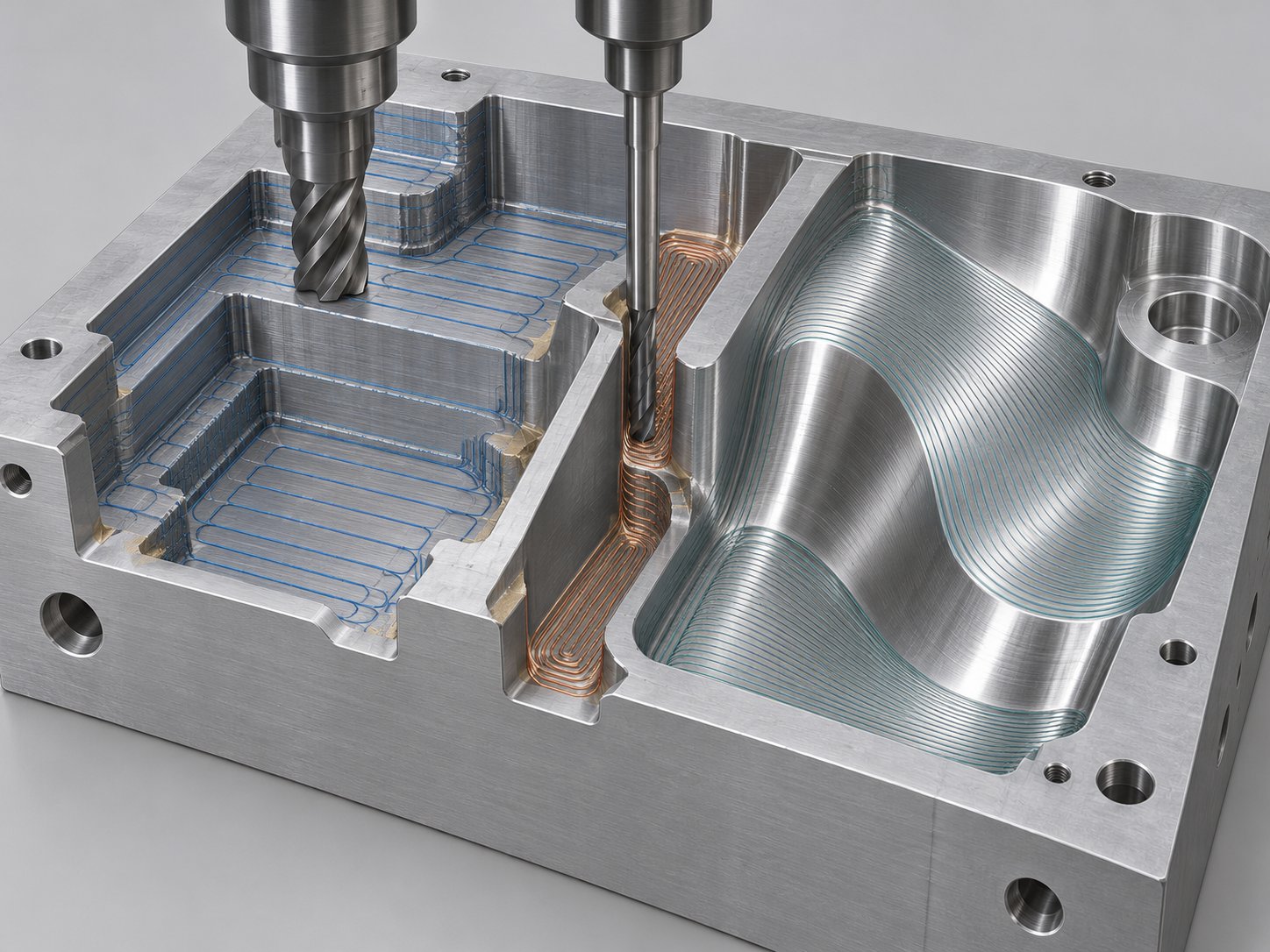
Therefore, the five-axis machining process should separately document the roughing allowance, rest-machining areas, and finishing acceptance surfaces. Roughing is evaluated by removal stability, rest machining by accessibility and remaining material, and finishing by contour accuracy, surface texture, and tool-axis continuity. The three have different evaluation criteria, so the reasonableness of the toolpath cannot be inferred solely from the final dimensional results.
What to check in five-axis toolpath simulation: collisions, overtravel, and rotary-axis anomalies
Five-axis toolpath simulation is not simply playing the toolpath once; it verifies whether the five-axis simultaneous milling program can run safely on the actual machine tool, fixture, and tooling system. Before simulation, establish a machine kinematic model consistent with the shop floor and import the blank, workpiece, fixture, tool, and tool holder. When the model lacks details of the rotary table, swivel head, or fixture, “machinable” in the simulation does not represent actual machining feasibility.
Inspection sequence for five-axis toolpath simulation
Inspection can proceed from near to far: first check whether contact between the tool’s cutting edge and the workpiece is continuous and whether overcutting, unmachined areas, or abnormal residual material occur; then check the clearances between the tool holder, fixture, rotary table, and swivel head. Next, observe the rotary-axis positions, effective travel, and limit areas, paying particular attention to overtravel, sharp rotation when approaching the limits, and rotary-axis reversal.
Rotary-axis anomalies and postprocessor output must also be verified
Can One Setup Guarantee Dimensional and Surface Quality in Five-Axis Machining? From Datums to First-Piece Inspection
Datums and Alignment Come Before the Toolpath in Five-Axis Machining
Dimensional, Contour, and Surface Quality Acceptance Must Be Conducted Separately

How to Request Accurate Quotes from Five-Axis Machining Suppliers: A Checklist of Drawing, Process, and Acceptance Information
Five-Axis Machining RFQ Information: Clearly Specify the Geometry and Acceptance Requirements First
Questions to Ask Suppliers About Five-Axis Toolpaths and Workholding Verification
- Will the process use 3+2 or simultaneous five-axis machining? Which areas require multiple setups, and how will the datums be transferred after re-clamping?
- Will a full machine-tool simulation be created based on the actual machine tool, rotary table or swivel head, fixture, tool holder, and blank? How will collisions, interference, axis overtravel, and abnormal rotation be checked?
- For deep cavities, angled holes, or continuous curved surfaces, is there a risk of inaccessible tool-axis orientations, excessive tool overhang, unstable contact points, or abrupt changes in surface texture?
- How should the first article be aligned and inspected? What datums and methods should be used for the key dimensions, surface contours, positional relationships, and inspection report, respectively?
The supplier should also be required to explain how out-of-tolerance dimensions are reported—for example, when the first article reveals excess stock on a curved surface or deviations in hole positions or assembly datums, who is responsible for confirming the cause, whether the toolpath or workholding needs to be adjusted, and how the part will be re-inspected after modification. The buyer does not need to require disclosure of every programming detail, but should receive the process judgments and verification records directly related to acceptance. The final comparison is not whether the supplier “has five-axis equipment,” but whether tool-axis accessibility, machining risks, and dimensional quality control can all be incorporated into the same delivery plan.
FAQ: Is five-axis machining always more suitable than three-axis machining for complex parts?
Determining whether five-axis machining is suitable cannot be based solely on the number of machine axes. The part features should be reviewed, including tool-axis accessibility, tool-holder and fixture clearance, rotary-axis travel, surface continuity, and the final inspection datums. Conclusions in the FAQ should be confirmed against the specific drawings, machine-tool kinematics, and first-article data.
Is five-axis machining always more suitable than three-axis machining for complex parts?
Not necessarily. Deep cavities, angled holes, features on multiple faces, or continuous freeform surfaces may be better suited to five-axis machining. However, if the part can be completed economically and reliably through properly planned 3+2 indexing, three-axis or 3+2 machining may also be the better option. The key is to compare accessibility, the number of setups, interference risks, and inspection requirements.
When is 3+2 machining sufficient, and when is simultaneous five-axis machining required?
When the machined surfaces can be grouped by fixed orientations and the tool does not need to continuously swivel at each orientation, 3+2 machining is usually sufficient. Blade-like continuous surfaces, narrow passages, or areas where the tool axis must be continuously adjusted to avoid interference are more likely to require simultaneous five-axis machining.
Does using five-axis machining for complex curved surfaces necessarily guarantee high precision?
No. Five-axis machining improves the tool approach direction and geometric accessibility, but dimensional results are also affected by material deformation, tool wear, the machine tool’s thermal condition, rotary-axis errors, the postprocessor, and the inspection method. Verification should be performed through simulation, first-article machining, and appropriate surface inspection.
Can a single setup replace dimensional inspection?
No. Reducing the number of setups may lower the risks of datum transfer and repeated positioning, but it cannot eliminate alignment errors, thermal drift, or tool deviations. Key dimensions, positional relationships, surface contours, and surface quality must still be accepted separately according to the drawing datums.
How can a buyer determine whether a supplier truly has five-axis machining capabilities?
Do not simply ask whether the supplier has five-axis equipment. Require an explanation of whether 3+2 or simultaneous five-axis machining will be used, the machine-tool kinematics and machining envelope, how tool-holder and fixture interference will be verified, whether full-machine simulation will be performed, and how the first-article and inspection reports will correspond to the drawing datums.
Key takeaways
- The core value of five-axis simultaneous machining is improving tool approach direction and geometric accessibility, not automatically achieving higher accuracy.
- 3+2 indexing is suitable for machining in fixed orientations, while continuous surfaces and areas prone to interference are more likely to require simultaneous five-axis machining.
- Tool-axis accessibility must be checked in conjunction with the tool, tool holder, fixture, rotary-axis travel, machine-tool envelope, and postprocessor.
- Roughing, rest machining, and finishing should be planned separately in terms of tool engagement, stock allowance, and surface texture.
- Dimensional control should begin with the datum, workholding, and inspection plans, and suppliers should be required during the quotation stage to explain their simulation and first-article verification methods.