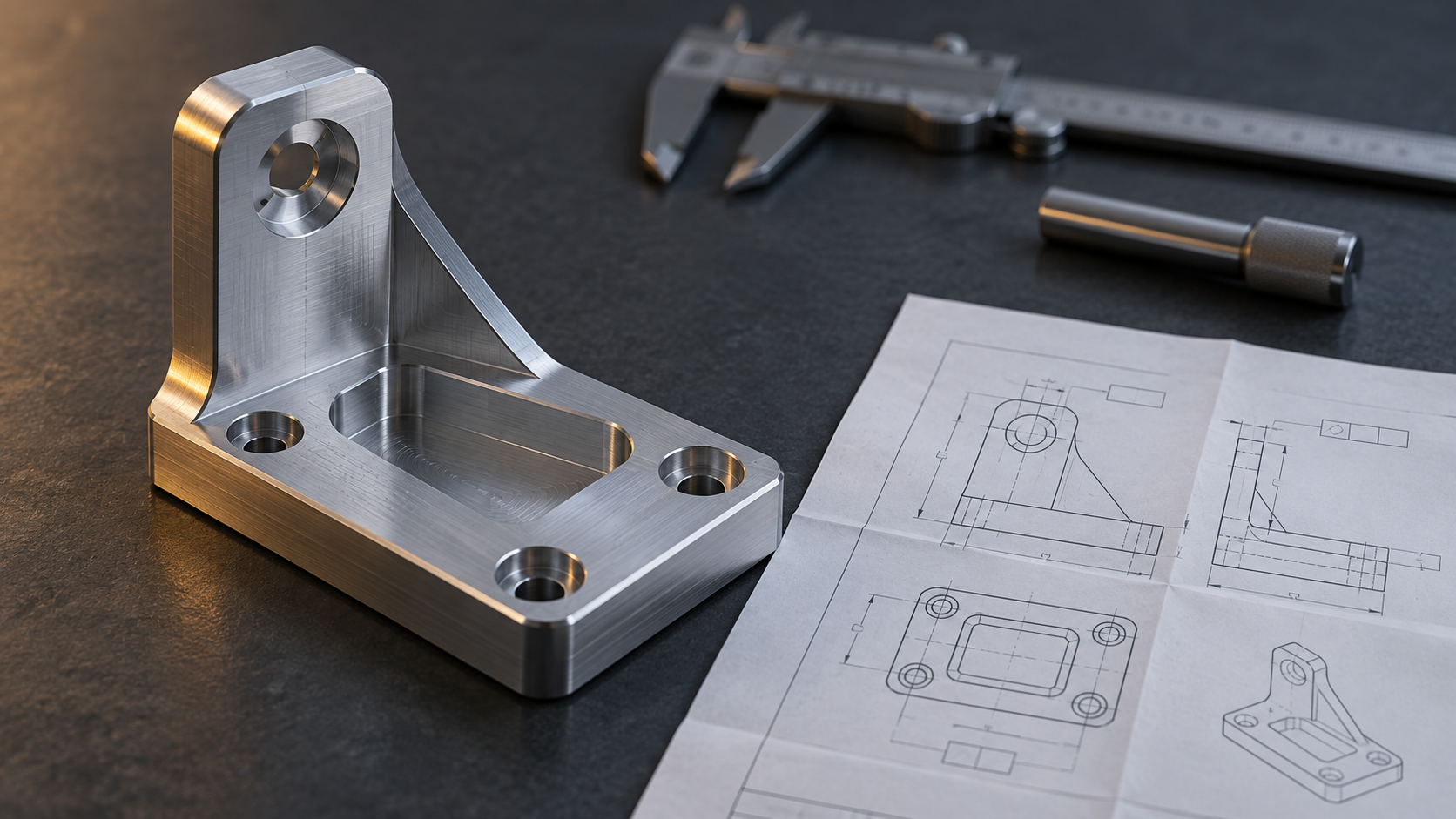
Start with one bracket drawing: the same part, three dimensioning methods, three outcomes
Suppose there is a 6061-T6 aluminum mounting bracket drawing, batch size 200 pieces, overall size about 120×80×25 mm, with features that are not particularly complex: the bottom face is the mounting face, two countersunk holes, one milled pocket 12 mm deep, and the bottom face of the pocket mates with the motor mount. The same geometry, drawn differently, leads to different actions in the shop and QC.
Option A: dimension only the basic overall dimensions, and write in the title block "unnoted tolerances per GB/T 1804-m." Option B: add on top of A the sentence "critical dimensions ±0.05." Option C: define the bottom face as datum A, the two countersunk holes as datums B and C, specify flatness on the mounting face, position on the hole locations, parallelism on the pocket bottom face, and H7 on the mating holes.
The geometry is exactly the same in all three drawing methods, but the quoting and risk are different. A is the least troublesome, but the shop does not know what must be held and what can be relaxed, so it can only run the whole part with a stricter process, and the number of setups and inspection labor will rise; B looks like a compromise, but the problem is that "critical dimensions" is undefined—the shop picks based on its own understanding, QC judges based on its own understanding, and rework disputes often arise here; C takes more time for upfront confirmation, but machining, inspection, and acceptance use the same datum system, so there is less wrangling later.
This article only discusses the drawing requirements themselves: datums, tolerances, material condition, roughness, and inspection conventions. It does not promise any specific price or lead time—those depend on quantity, scheduling, and the actual machining route, and need to be confirmed against the drawing.
Datums and datum systems: the first priority in drawing requirements
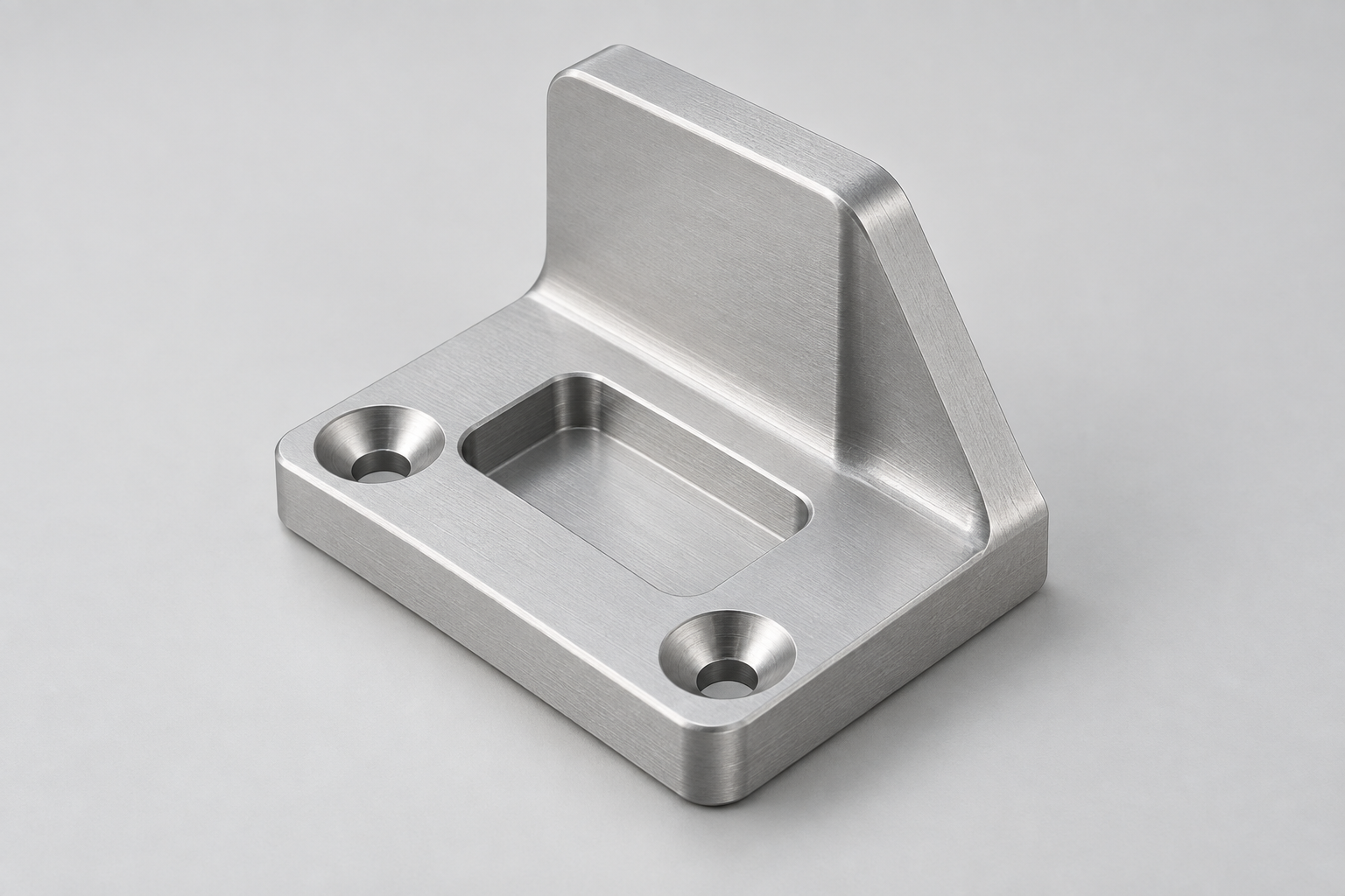
Back to that 6061-T6 bracket. Option A dimensions only the overall dimensions and general tolerances; the shop aligns to the blank outline, and after milling the pocket, drills the two countersunk holes casually. QC measures the hole spacing with calipers, finds a 0.08 mm deviation, and judges it acceptable—but when it is mounted on the motor mount, the hole positions do not line up. The dispute is not about the size of the tolerance, but about the fact that the two sides are not using the same datum at all.
This is why datums must come first: if the datums are not fixed, no matter how nice the tolerance numbers look, everyone is just talking past each other. The design datum is the face by which the part is positioned functionally; the process datum is the face by which the shop aligns during fixturing; the inspection datum is where QC places the part for measurement. When the three are inconsistent, the same batch of parts will receive two different judgments, and the cost of rework and wrangling is much higher than adding a few more lines of tolerances.
How datums are established on a bracket drawing
A common approach is: the bottom face serves as primary datum A (it is simultaneously the functional face that mates with the motor mount, the fixturing face during milling, and the placement face for CMM, unifying all three); the two pin holes serve as secondary datum B and tertiary datum C, used to constrain hole spacing and angle. With this dimensioning, position, parallelism, and perpendicularity all hang on the same datum system, and the shop and QC read the same statement.
- Datums should be chosen as functional faces, not just any large flat surface. If a non-functional face is used as a datum, the deviation of the datum itself is only discovered during assembly, which means the dimensioning was pointless.
- Datums must not over-constrain. Using two datums to lock the same direction at the same time creates over-positioning, and actual machining cannot satisfy both at once.
- Datums should coincide with fixturing faces as much as possible. The farther apart the design datum and process datum are, the greater the alignment error, and the more the process depends on fixture compensation.
- If the datum changes, the inspection plan must change with it. A drawing revision that upgrades the version but does not update the gauges is a common cause of first-article rejection.
The most problematic case is when the second and third points are violated at the same time: using the outer side face as the datum while the shop actually fixtures on the bottom face and two process holes. This kind of drawing shows no problem at the quoting stage, but it is exposed at first article—the supplier either adds a dedicated fixture or machines to its own datum and then has QC re-measure to the drawing datum, and the results will inevitably fail to match. Writing the datum system clearly on the drawing is the first step to converging quoting differences, and it is also the prerequisite for whether CNC machining can get it right the first time.
Dimensional tolerances and geometric tolerances: what should be tightened, and what only adds cost when tightened
The most common mistake on a bracket drawing is to dimension the entire drawing uniformly as ±0.05. This number looks safe, but in practice it puts all the cost on the tool tip: to hold ±0.05 on non-mating outer contours, the shop must reduce cutting parameters, add passes, and adjust tools frequently; to judge acceptance, QC must probe every dimension with a CMM, and inspection labor may be longer than machining. But the ones that truly need ±0.05 are often only two mating holes and one mounting face.
The judgment logic is simple: first ask whether this dimension constrains function or form. If it constrains fit, guidance, sealing, or assembly interchangeability, tightening is justified; if it only constrains the cosmetic contour or non-contact surfaces, tightening merely converts machining difficulty into cost with no functional benefit. Another more critical point: relationships that can be clearly expressed with geometric tolerances should not be stacked with a chain of linear dimensions. Hole spacing dimensioned with position allows both machining and inspection to calculate deviation directly from the datum; dimensioning the coordinates of two holes separately with ±0.05 means the same hole position deviation will accumulate across two chains, making the judgment convention even more ambiguous. If position is dimensioned with MMC (maximum material condition), it can also leave fit allowance for holes and pins, giving both the shop and the gauges some relief.
| Mating holes / bearing seats | H7 mating holes commonly IT7 grade; bearing seats often selected by shaft diameter fit | Requires reaming or fine boring, inspection switches to plug gauges/inside micrometers, and per-piece labor rises | Non-rotating, non-guiding through holes can be relaxed to IT9–IT10 or even looser |
| Mounting face flatness | Common for small and medium parts 0.02–0.05 mm; fine milling can be tighter | Requires fine milling or grinding, fixturing must prevent deformation, inspection uses surface plate plus feeler gauge or CMM | When elastic washers or sealant compensate, it can be relaxed to the 0.1 mm level |
| Hole spacing position tolerance | Commonly φ0.1–φ0.2 mm (relative to datum) | Requires single setup or dedicated fixture to guarantee; inspect with position gauge or CMM | When assembly has clearance fit or adjustable structure, can relax to φ0.3 mm or more |
| Non-mating contour | Generally ±0.2–±0.5 mm is sufficient | Tightening to ±0.05 only adds cutting passes and inspection, no functional benefit | If the contour does not participate in assembly or mating, relax directly |
| Threaded pilot hole | Look up per thread specification; position tolerance often relaxed | Tightening pilot hole position will interfere with thread pitch diameter, not worth it | When thread is only for fastening, not locating, pilot hole position tolerance can be significantly relaxed |
| Chamfer / deburring | Often marked 0.5×45° or "remove sharp edges" | Over-specifying chamfer dimensions forces the shop to use form tools, increasing tool changes | Non-assembly lead-in angles can just be marked "deburr" without specific dimensions |
Back to the bracket drawing: tightening the position tolerance of the two counterbore holes to φ0.1 and specifying 0.03 flatness on the mounting face is reasonable; pressing the cavity contour and base plate outline to ±0.05 as well is a typical "one-size-fits-all." If the assembly side indeed has clearance and is adjustable, relaxing the hole spacing to φ0.3 is actually more robust—the margin is given to the gauge, and also gives the shop the space to guarantee it in a single setup. Which step should be rolled back? When the drawing only says "critical dimensions ±0.05" without stating which is critical, where the datum is, and how to measure, quotes can only be estimated along the most conservative path, and the designer ultimately pays.
Material, condition, and heat treatment: if unclear, material will be substituted or process changed
Back to that bracket drawing. The material field only says one word: aluminum alloy. With just that one word, procurement might order 6061-T6, or might order 6063 or 7075; the shop schedules the process for the worst case, keeps cutting parameters conservative, and the quote naturally goes up. By the time the parts come back for anodizing, only then is it discovered the material condition is wrong, the color is mottled, and the whole batch is reworked.
Grade and temper must be written together. 6061-T6 and 6061-O are two different machining behaviors, two different deformation behaviors, and two different subsequent treatment results. If the temper is unclear, you are handing material selection to the supplier, and the supplier will only choose the one easiest to buy and least likely to cause trouble—not necessarily the one you want.
The four questions the material field must at least answer
- Grade and temper: write the complete designation such as 6061-T6, 304, 17-4PH (solution + aging); do not write "stainless steel" or "aluminum alloy."
- Whether substitution is allowed: if equivalent substitution is allowed, note the substitute grade and the items requiring re-confirmation after substitution; if not allowed, state it firmly.
- Heat treatment requirements: hardness range, aging temperature, stress relief process, and whether heat treatment comes before or after rough machining.
- Stress relief requirements: for cavity parts, long cantilevers, and thin-wall parts, if not specified, deformation after rough machining will directly eat into the finishing allowance.
The sequence of heat treatment and finishing is the line most easily missed on this bracket drawing. If the drawing only says "quenching and tempering" without specifying the process position, the shop may finish machine first and then heat treat; hardness goes up, and dimensions drift too. The common practice is rough machining with allowance → stress relief/heat treatment → semi-finish → finish; but how much allowance and when to do it must be confirmed with engineering when not specified on the drawing—it cannot be assumed.
| "Aluminum alloy" | Select 6061 or 6063 based on stock | Anodizing color difference, insufficient hardness, cutting parameter mismatch |
| "6061" with no temper | May arrive as T4 or O condition | Deformation after finishing, flatness out of tolerance |
| "Stainless steel" | May arrive as 304 or 303 | 303 contains sulfur; welding and corrosion resistance differ, mating surface life differs |
| "Heat treatment: quenching and tempering" with no process position | Shop decides the sequence on its own | Dimensional drift after heat treatment, insufficient finishing allowance |
Material condition also affects whether subsequent surface treatment can be implemented. 6061-T6 has relatively stable color after anodizing, while 7075 with high copper content tends to darken after oxidation; 304 and 303 differ in corrosion resistance. If the drawing writes material, condition, and surface treatment clearly as a linked chain, the supplier will not have to make these decisions for you at the quotation stage.
Surface roughness, deburring, and appearance requirements: the three lines most easily omitted
Back to the bracket drawing. The cavity bottom is the mounting face that fits against the motor mount, the two countersunk holes are for M5 screws, and the outer contour is a non-functional surface. The designer wrote only one note on the entire drawing: "Ra1.6." The shop interpreted it most conservatively and ran all surfaces at Ra1.6—including the outer contour. Result: cutting time was lengthened, tool consumption increased, and the roughness of the outer contour contributed nothing to appearance or assembly. This is the classic case of "one line of roughness callout driving up the cost of the whole part."
Roughness must be written by functional surface category, not as a single value for the entire drawing. A common industry practice is: sealing surfaces and sliding fit surfaces controlled to Ra0.8–Ra1.6; general mounting fit surfaces Ra1.6–Ra3.2; non-mating contours and non-functional surfaces Ra6.3–Ra12.5 is sufficient. These are reference ranges; confirm the specific values according to the drawing's functional requirements and the shop's actual capability. When the drawing does not specify, the machinist usually applies economic roughness, but this "default value" is understood differently by different parties and easily leads to disputes at acceptance.
Deburring and chamfering: if not written, it defaults to "not handled"
If deburring is not written on the drawing, it does not mean deburring is unnecessary—but the machinist may treat it as "not required." The consequences are concrete: burrs at the edges of countersunk holes scratch the mating surface during assembly; burrs at threaded openings affect screw-in; during subsequent plating, pinholes form at burrs. The bracket drawing should at least specify: deburr all sharp edges (can use "break sharp edges" or note chamfer C0.3–C0.5), chamfer thread entries, and no residual rolled-over edges allowed at cavity corners.
Appearance requirements: distinguish functional defects from appearance defects
Wording such as "no scratches" cannot be inspected and is not actionable. It should be distinguished: defects affecting function (cracks, missing material, crushing on mating surfaces)—not allowed; purely appearance defects (slight tool marks on non-functional surfaces, color difference)—acceptable or judged by a limit sample. If the outer contour of the bracket is exposed, it can be noted: "Non-functional surfaces may have machining marks; impacts deeper than 0.2 mm are not allowed." In this way, quality inspection has a basis, and the shop will not scrap an entire part because of an invisible tool mark.
| Location | Recommended callout | Consequence of omission |
|---|---|---|
| Motor mount mounting face | Ra1.6, flatness noted separately | Poor fit, vibration, assembly gap |
| Countersunk hole conical face | Ra3.2, deburr | Screw head does not seat, scratches |
| Outer contour non-functional surface | Ra6.3 or not noted | Whole-drawing Ra1.6 causes unnecessary machining time |
| Thread entry | Chamfer C0.5, deburr | Difficult screw-in, plating pinholes |
Inspection criteria and first article: the drawing must be able to answer "how is acceptance judged"
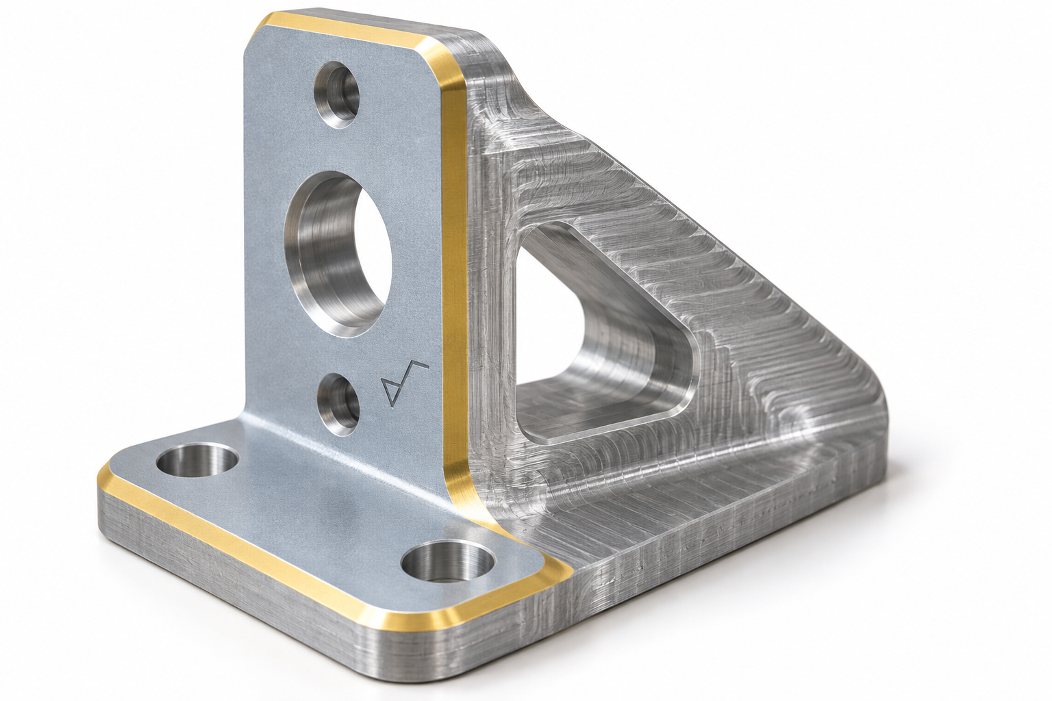
Back to the bracket drawing. Quality inspection placed the part on a CMM and established the coordinate system according to datum A (bottom face) on the drawing, measuring the hole spacing position tolerance as 0.12; the shop aligned and clamped according to the pin holes and self-measured 0.06. Neither side lied; the standards were different. This kind of dispute is not a machining accuracy problem; it is that the drawing did not clearly state "according to which datum and by what method acceptance is judged."
Key dimensions must specify the measurement method
If the drawing only specifies tolerances and not the inspection criteria, it leaves the judgment to the supplier. A common practice is to assign by dimension type: for functional dimensions such as mating holes and pin holes, specify pin gauges/plug gauges or CMM; for flatness of mounting faces, use CMM scanning or surface plate with indicator; for threads, use thread gauges; for outer contours, use a projector or scan comparison. A common industry practice is to list key dimensions separately in an "inspection items" column on the drawing, but as to exactly which dimensions and which gauges, when the drawing does not specify, confirm with engineering; do not assume the shop will choose the strictest method.
Full inspection, sampling, and first article: the three levels must be written separately
For 200 brackets, if all dimensions are fully inspected, inspection time may exceed machining time, and this cost will ultimately enter the quotation. Reasonable tiering: fit dimensions and geometric tolerances fully inspected or high-proportion sampled; non-functional contours, chamfers, and deburring by first article plus sampling; material condition and heat treatment by quality certificate. The first article report should include: CMM measured values compared with drawing nominal values and tolerances, datum establishment description, list of gauges for key dimensions, appearance and deburring confirmation, material/heat treatment certificates. If the first article is not passed and batch machining proceeds, rework cost is far higher than stopping the line for confirmation.
| Datum establishment | A datum (bottom face) alignment method, pin hole positioning | Consistent with drawing datums |
| Position tolerance | Measured values of the two pin holes relative to A/B/C | Compare with drawing tolerance zone |
| Flatness | Mounting surface scan or dial indicator data | Compare against drawing requirements |
| Mating holes | Pin gauge/plug gauge go/no-go | Go gauge passes, no-go gauge does not pass |
| Appearance and deburring | Edges, hole openings, thread openings | No sharp edges, no risk of coating pinholes |
| Material and heat treatment | Grade, condition, quality certificate | Consistent with drawing annotations |
This section is also a major source of supplier quotation differences. For the same drawing, Company A quotes based on full CMM inspection, while Company B quotes based on caliper sampling inspection. The price difference may come from the inspection scope rather than machining capability. Writing the inspection requirements clearly before quoting is far more useful than arguing afterward that "you didn't say that at the time."
Back to that bracket drawing: comparison of results and decision for three annotation schemes
Apply the criteria from the previous five sections back to that 6061-T6 bracket drawing. Scheme A gives only the overall external dimensions and one general tolerance frame; Scheme B selects a few "critical dimensions" and marks them ±0.05; Scheme C establishes a datum system, position tolerance, flatness, and surface roughness annotations by face. For the same geometry, the differences among the three drawing methods across the four dimensions of quotation, scrap, inspection, and communication are much greater than the geometry itself. Below is a qualitative comparison under the same batch size of 200 pieces and the same fixturing conditions; the values only indicate direction of judgment and are not commitments.
| Quotation uncertainty | High: suppliers leave margin based on worst case, and quotes vary widely | Medium: critical dimensions are guessed, and non-critical faces remain ambiguous | Low: labor hours and gauges can be estimated from the drawing, and quotation scope is consistent |
| Scrap and rework risk | High: nonconforming mating surfaces are discovered only after machining release | Medium: fixturing surfaces and measurement datums are inconsistent, causing repeated judgment | Low: datums are unified, and out-of-tolerance conditions can be traced to the process step |
| Inspection labor hours | Low on the surface, high in practice: full-dimensional supplementary inspection is needed during disputes | Medium: critical dimensions require CMM, while non-critical faces still cause arguments | High upfront, low overall: gauges are in place once, and sampling inspection is sufficient |
| Communication rounds | Many: material condition, roughness, and deburring all require follow-up questions | Medium: position tolerance and flatness scope easily cause back-and-forth | Few: the drawing answers most questions by itself |
| Applicable scenarios | Single piece, non-mating, internal trial assembly | Prototype, before functional verification | Mass production, with mating and assembly requirements |
The recommended final approach is not to blindly choose C, but to "use C as the skeleton and remove excessive annotation on non-functional faces." Specifically: keep datum A and the two pin holes B/C; apply flatness and position tolerance to the motor mount mating face; give only contour dimensions and a relaxed tolerance band to the cavity bottom and side faces; apply general tolerances to non-mating external features and note "per GB/T 1804-m or equivalent unspecified tolerances." In this way, critical dimensions are complete, non-critical faces are clearly relaxed, and inspection resources are concentrated on the few places that truly affect assembly.
When should you return the drawing for supplementation instead of forcing a quote: mating relationships are unclear (what it assembles with, how much clearance), material condition is missing (only "aluminum" is written), heat treatment and finishing sequence are not specified, datums and fixturing surfaces clearly conflict, or the entire drawing has one roughness value yet includes sealing faces. These are not details; they are prerequisites that determine the process route. When you need an estimate based on a drawing, you can first confirm the feasible scope through the AI conversational quoting or the CNC machining capabilities page.
Drawing review checklist: go through it yourself before quoting
Condense the content of the previous six sections into a checklist you can tick off. The usage is very direct: go through it yourself before quoting, and fill in whatever is missing. Whatever cannot be filled in is exactly what the workshop will definitely come to ask you about.
- Datums: Does the primary datum correspond to the actual clamping surface? Are the inspection datums consistent with the design datums?
- Tolerance allocation: Is the fit type (clearance/interference/transition) specified for every mating dimension? Have one-size-fits-all tolerances been avoided?
- Material condition: Are the grade and condition complete (e.g., 6061-T6, 304, 17-4PH solution-treated and aged)? Are substitutions allowed?
- Heat treatment and stress relief: Is the process sequence specified (rough machining → stress relief → finish machining)?
- Roughness: Is Ra specified per surface for functional surfaces? Is the default value for unmarked surfaces stated?
- Deburring and chamfering: Is blunting or deburring of sharp edges explicitly required?
- Threads: Are thread specifications, depth, and pilot hole requirements clear?
- Inspection criteria: Are the measurement methods or referenced standards for critical dimensions specified?
- Version and changes: Are the drawing number, version number, and change records complete?
- Units and projection angle: Are mm/inch consistent? Is first-angle or third-angle projection indicated?
- Hidden line ambiguity: Are the section views sufficient to express the internal structure? Are there any self-contradictory views?
- Relaxation for non-functional surfaces: Are relaxed tolerances or roughness explicitly specified for non-mating surfaces?
This checklist is for CNC milled/turned parts. Sheet metal parts also require consideration of the bend allowance, bend radius and K-factor, and burr direction; 3D printed parts require consideration of wall thickness, support surfaces, layer orientation, and anisotropy; injection molded parts require consideration of draft angle, wall thickness uniformity, gate location, and sink mark risk. Do not apply the CNC checklist directly to other processes.
Common reasons for rejection, ordered by frequency: missing material condition, no tolerance on critical mating dimensions, contradiction between datum and clamping surface, roughness specified as a single value for the entire drawing, blank deburring requirements, version number not matching the file name. The first three account for nearly half of all rejections.
Common questions
The following questions are the ones most often asked before quoting and the ones most likely to hide pitfalls in the drawing. The answers are given for CNC parts such as bracket drawings; changing the process requires re-evaluation.
If no tolerance is marked on the drawing, what does the shop work to?
Most shops will follow an unspecified tolerance table, and the common industry practice is to use a medium precision grade for linear dimensions (such as GB/T 1804-m), but which grade is used and whether it is segmented by size varies from shop to shop. So "not marked" does not mean "make it however," it means "the supplier decides for you." For functional surfaces, mating holes, and mounting surfaces, it is better to specify clearly yourself than to leave it for the other party to guess. If critical dimensions are found to have no tolerance before quoting, the drawing will usually be returned for confirmation.
What practical effect does marking position tolerance with MMC have on machining and inspection?
The maximum material requirement (MMC) allows extra tolerance when the actual hole size deviates from maximum material, essentially giving the machining allowance to position error. For the shop, making the hole on the larger side of the tolerance band makes the position tolerance easier to meet; for quality inspection, functional gauges (pin gauges, position tolerance gauges) can replace point-by-point CMM measurement, significantly reducing inspection time. The premise is that the drawing clearly shows the MMC symbol and that the function truly allows this compensation. Do not use it where the assembly relationship is strict and compensation is not allowed.
Can I get a quote if I only write "aluminum alloy" or "stainless steel"?
Yes, but the quoted price and lead time will be highly uncertain. The grade, condition, heat treatment, and whether substitution is allowed directly determine cutting parameters, tool selection, distortion control, and whether stress relief is needed. 6061-T6 and 6061-O behave noticeably differently in machining; 304 and 17-4PH also differ completely in tool wear and heat treatment sequence. When the drawing lacks this information, the supplier will either quote based on the most conservative assumptions or come back to ask. It is recommended to write the full grade plus condition in the title block or technical requirements and note the substitution rules.
Is it acceptable to write a single Ra1.6 for the entire drawing?
Technically feasible, but the cost is relatively high. Sealing surfaces and sliding mating surfaces may require Ra0.8 or finer, while most non-functional exterior surfaces are fine at Ra3.2 or coarser. Applying Ra1.6 uniformly across the entire drawing means all surfaces are cut to a finer requirement, which increases machining time and cost. The common practice is to specify roughness by functional surface category and explicitly relax non-functional surfaces or write "unspecified Ra3.2." The specific categories should be confirmed according to the drawing's function and the shop's capability; do not copy someone else's values.
What items should a first article report include?
At minimum it should cover: all toleranced dimensions and geometric tolerance items on the drawing, critical mating dimensions, material grade and condition certification, heat treatment records (if any), surface treatment and roughness sampling results, and a description of the datums and gauges used for measurement. The measurement datum must be consistent with the drawing datum; if not, the conversion method must be explained in the report. Which dimensions are fully inspected and which are sampled should preferably be agreed in advance on the drawing or order; otherwise, if the first article passes but problems arise in mass production, disputes are likely.
Key takeaways
- Define datums before dimensioning: design datums, process datums, and inspection datums should be unified as much as possible; otherwise, the same drawing will become two different parts in the hands of the shop and QC.
- Tolerances are not as tight as possible: do not tighten dimensions that can be naturally ensured by tooling and fixturing; only dimensions that assembly or function truly depend on are worth tightening and equipping with gauges.
- A drawing must answer three things: material and condition, the inspection convention for critical dimensions, and how non-critical surfaces are handled (deburring, chamfering, surface condition). Missing any one of these will lead to back-and-forth confirmation during quoting or first article.
- Geometric tolerances take priority over equivalent stacked dimension chains: expressing coaxiality, perpendicularity, and position with GD&T is less likely to create ambiguity than using multiple linear dimensions plus notes.
- Clearly stating "not required" is equally important: explicitly relaxing tolerances on non-mating, non-sealing, and non-cosmetic surfaces can directly reduce machining and inspection costs.



