What Structural Features Do Box-Type Parts Have? Why Are They Difficult to Machine?
Box-type parts support components such as shafts, sleeves, and gears and maintain their relative positions after assembly. Common examples include machine-tool headstocks, feed boxes, gearboxes, reduction gearboxes, engine blocks, and equipment bases. Structurally, boxes can be divided into integral and split boxes: integral boxes are typically cast as a single piece and then machined, offering better overall integrity but poorer accessibility for machining internal cavities and hole systems; split boxes are easier to machine and assemble separately, but they impose additional requirements on mating surfaces, locating relationships, and assembly adjustment.
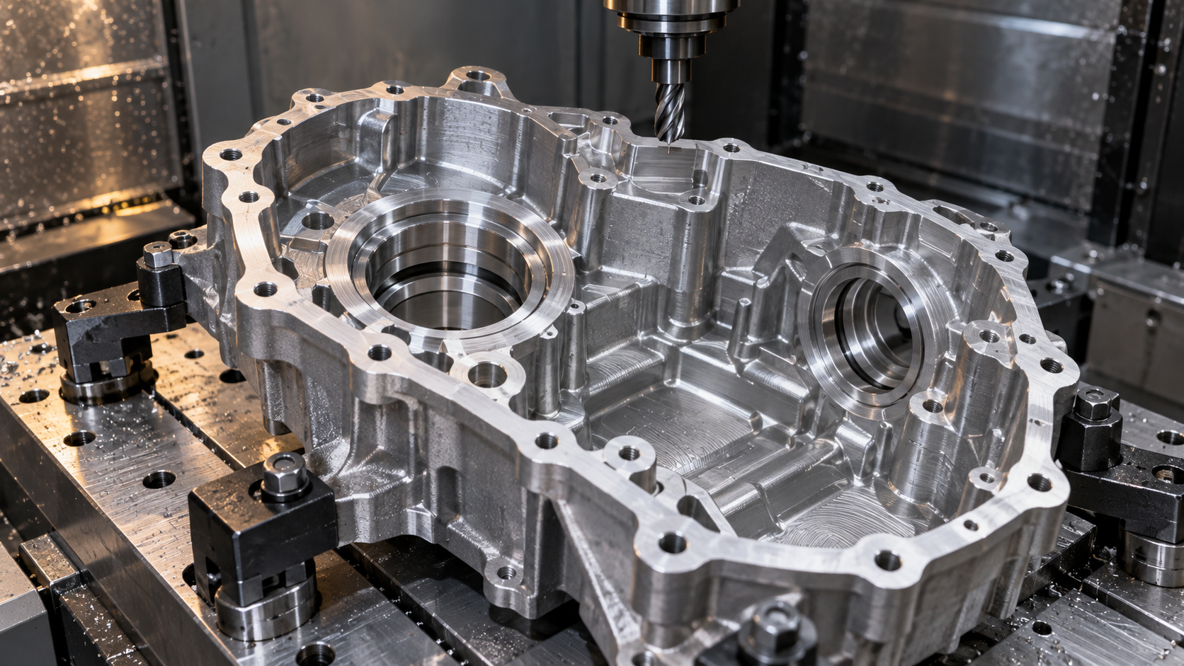
First, box-type parts are difficult to machine because of their irregular shapes. Their exteriors may include mounting surfaces, steps, and bosses, while their interiors contain cavities, ribs, island features, and hole systems in different directions. The box walls may also have uneven thickness, and residual stress after casting or welding can be released when material is removed during rough machining, causing local deformation. Deep-cavity areas are constrained by tool overhang, chip evacuation, and visibility, while clamping positions must balance rigidity and accessibility.
Second, the quality requirements for boxes are typically concentrated on datum planes, guideway surfaces, bearing bores or spindle bores, and the relationships among mutually perpendicular, parallel, or coaxial hole systems. Fastener holes may only need to meet assembly clearance requirements, whereas primary hole systems must be controlled according to the drawing for dimensions, hole spacing, coaxiality, and positional relationships. If processes are selected only according to whether a milling machine, drilling machine, or lathe is used, it is easy to overlook the workpiece features, locating datums, repeated clamping, and tool accessibility. Machining box-type parts should first identify the function of each feature, then determine the combination and sequence of milling, drilling, boring, and other operations.
Key Machining Operations for Box-Type Parts: From Datum Surfaces to Hole Systems and Cavities
Machining a box-type part is not simply a matter of processing an outer shell; it establishes assembly relationships around mounting datums, support surfaces, hole systems, and internal spaces. The bottom, side, or mounting platform usually serves a locating function first. Subsequent machining must be based on the datums specified in the drawing, with emphasis on controlling flatness, parallelism, perpendicularity, and the mutual positional relationships with other mounting surfaces.
Datum Surfaces, Top Surfaces, and Guideway Surfaces
The bottom and primary side surfaces are commonly used for workpiece locating and clamping, with milling generally used to establish the initial precise datum. Top surfaces, step surfaces, and guideway surfaces determine the mounting height and direction of movement of slides, cover plates, or other components and may be divided into roughing, semi-finishing, and finishing operations according to the machining allowance. If a guideway surface requires high straightness or surface quality, grinding may be scheduled as a subsequent operation. Whether finishing is required depends on the material, heat-treatment condition, and drawing tolerances.
Primary Hole Systems, Transverse Holes, and Threaded Holes
Spindle bores, bearing bores, and sleeve bores are core features in machining box-type parts. They must satisfy not only diameter requirements but also requirements for roundness, coaxiality, and the parallel or perpendicular relationship between the hole axes and datum surfaces. Drilling is commonly used for pilot holes and some through-holes; when dimensional or positional requirements are higher, boring, reaming, or similar operations are generally added. Transverse holes may intersect the main bore, so tool accessibility, burrs at intersecting hole openings, and the mutual positional relationships among hole systems must be considered.
Threaded holes, locating holes, and fastener holes are mostly secondary holes, but they still affect assembly. During machining, the functions of threaded-hole tapping holes, counterbores, countersinks, and locating holes should be distinguished to avoid treating the accuracy of ordinary drilled holes as the final requirement. Chamfering hole openings, removing burrs, and cleaning away residual chips are also indispensable processes before machining of the box-type part is complete.
Internal cavities, island structures, and thin-wall regions
Box interiors often contain multiple cavities, ribs, and island structures. Milling toolpaths must be planned according to the opening direction, tool overhang, and chip evacuation conditions; deep cavities or narrow slots may require layer-by-layer stock removal, along with checks for potential collisions between the tool and fixture. Thin-wall regions have relatively low rigidity, and cutting loads, clamping pressure, and stress release from stock removal may all cause deformation. Therefore, the machining sequence should be arranged based on wall thickness, material, and structural characteristics, rather than selecting the process solely according to external dimensions.
Common machining processes for box-shaped parts: milling, drilling, boring, and finishing
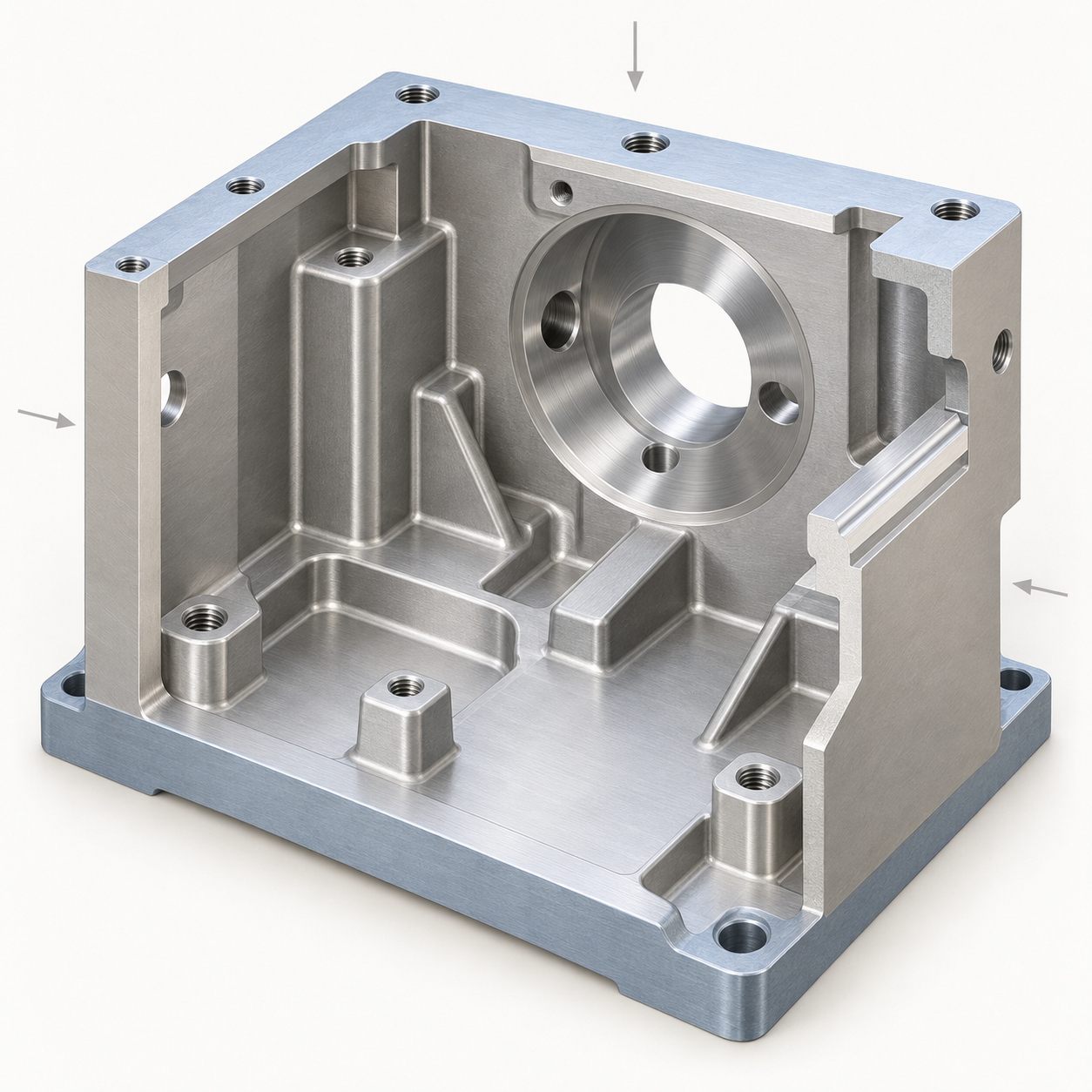
Machining processes for box-shaped parts cannot be selected solely by equipment type; the features to be machined must be considered first. Planes, steps, external profiles, and internal cavities are generally machined primarily by milling; ordinary through holes, pilot holes, and some threaded holes are typically drilled; main bearing bores, spindle bores, or hole patterns with positional requirements often require subsequent boring, reaming, or similar operations. Process selection is also constrained by the material, hole depth, wall thickness, clamping method, and drawing tolerances.
Milling in box-part machining: processing planes, steps, and cavities
Milling is primarily used for machining datum surfaces, mounting surfaces, guideway surfaces, steps, external profiles, and internal cavities. Rough milling removes most of the stock while leaving an appropriate allowance for subsequent operations; semi-finishing and finishing then control planar dimensions, parallelism, and surface quality. Boxes with multiple cavities also require the machining of island structures, deep cavities, and narrow regions. Excessive tool overhang may reduce rigidity, while too many repeated setups increase the risk of datum shift. Toolpaths should therefore be planned in conjunction with tool accessibility, chip evacuation, and fixture interference checks.
Drilling, boring, and reaming in box-part machining
Drilling is suitable for through holes, pilot holes, and some threaded holes, and is generally a preliminary operation in hole-pattern machining. However, drilling should not be equated directly with final finishing. Drill performance is readily affected by cutting-edge condition, material, hole depth, and chip evacuation. When requirements for hole size, roundness, coaxiality, or surface quality are high, boring or reaming may be used from a stable datum. Boring allows the size of each hole to be adjusted individually and is also suitable for controlling positional relationships between holes and mounting surfaces or between adjacent holes. Reaming is better suited to hole finishing when the tool, allowance, and hole structure are appropriate, and the condition of the pre-machined hole must be stable.
The boundary between turning and grinding in box-part machining
Turning is not the general first choice for the main body of a box-shaped part and is usually limited to bearing seats, cylindrical steps, or rotational features that can be processed on mill-turn equipment. If a cylindrical bore has strict positional relationships with the box datum or other hole patterns, an integrated setup and boring process should still be prioritized. Grinding is used when the drawing imposes higher requirements on planes, cylindrical surfaces, dimensional stability, or surface roughness. The final process route should be determined based on the drawing datums, tolerance zones, material, and equipment capabilities, rather than conclusions based solely on the nominal accuracy of a particular process.
How should a typical machining process flow for box-shaped parts be arranged?
Machining box-shaped parts is generally not arranged simply according to an equipment sequence of “mill first, drill next, and inspect last.” Instead, operations are organized around blank stability, datum establishment, and the accuracy of major surfaces and hole patterns. A typical route can be summarized as follows: blank preparation and any necessary aging or stress-relief treatment → initial positioning or layout marking → establishment of reliable datum surfaces → machining of major planes and guideway surfaces → machining of major hole patterns → machining of cross holes, threaded holes, and secondary holes → chamfering, deburring, cleaning, and inspection. The actual sequence must still be adjusted according to the material, structure, equipment accessibility, production volume, and drawing requirements.
Handling the blank and initial datums first in box-part machining
For cast box-shaped parts, first inspect the blank allowance, shrinkage cavities, sand inclusions, and deformation risks. For large parts or parts with significant residual stress, whether to arrange aging, stress relief, or a stabilization waiting period should be determined based on the material and actual deformation behavior. For welded boxes, attention must be paid to post-weld deformation; straightening or stabilization treatment may be necessary. Layout marking is suitable only for situations requiring the establishment of initial positional relationships and cannot replace reliable subsequent machining datums. The first machining operation usually selects a relatively large surface with a clear assembly relationship to establish the locating datum required for subsequent setups.
Machining planes and major hole patterns from established datums in box-part machining
After establishing the datum surfaces, rough-machine the major planes, bottom surface, mounting surfaces, or guideway surfaces first, prioritizing the removal of most of the stock while controlling deformation in thin-wall and uneven-wall-thickness regions. Semi-finishing is then performed, leaving stable and uniform stock for finishing. Major hole patterns are generally rough-machined first, followed by semi-finishing and finishing operations arranged according to requirements for size, coaxiality, roundness, and surface quality. When a hole pattern has a defined positional relationship with a mounting surface, unified or traceable datum positioning should be used whenever possible to reduce errors in hole spacing, parallelism, and perpendicularity caused by repeated setups.
Processing secondary holes, threads, and cleaning and inspection last in box-part machining
Cross holes, threaded holes, tapped holes, locating holes, and other secondary holes are usually machined after the major datums and hole patterns have stabilized. However, some holes may be scheduled earlier if they affect subsequent clamping or tool access. After machining, chamfers and burrs at hole openings should be treated, and chips should be removed from cavities, intersecting holes, and threads before cleaning. Final inspection should be conducted around the drawing datums, checking critical dimensions, hole-pattern positions, flatness, parallelism, perpendicularity, or coaxiality rather than measuring only individual hole diameters. For large castings or welded parts, whether additional stabilization treatment is required after rough machining should also be determined according to deformation trends and the remaining finishing allowance.
Why should the datum surfaces and primary hole systems be machined first when processing box-type parts?
Parallelism, perpendicularity, hole spacing, or coaxiality requirements usually exist among the bottom surface, mounting surfaces, guideway surfaces, and primary hole systems of box-type parts. Machining and confirming the main locating surfaces first establishes stable, repeatable fixturing conditions for subsequent operations. If cast surfaces, welding-distorted surfaces, or unverified external profiles are used directly for locating, the part orientation may change with every setup, and positional errors in the hole system can easily accumulate during successive datum transformations.
Datums and fixturing in box-type part machining
In actual machining, a surface closely related to the assembly, relatively large in area, and convenient for support is usually selected as the rough datum. Rough and semi-finish machining of the bottom or main mounting surface is then completed before switching to the machined surface as the finish datum. The locating surface should, as far as possible, be consistent with the drawing datum and inspection datum. If the process datum differs from the design datum, the effects of the resulting dimension-chain changes must be checked. For boxes with deep internal cavities or uneven wall thicknesses, clamping force should also be controlled to prevent insufficient support, local indentations, or deformation during fixturing.
Why should primary hole systems be machined on stable datums?
Main spindle bores, bearing bores, and interconnected transverse holes often directly determine the assembly positions of shafts, sleeves, and gears. During rough machining, most of the allowance can first be removed while leaving a reasonable allowance for subsequent boring, reaming, or other finishing operations. Finish machining should be performed with the datum stable, cutting-heat effects limited, and part deformation essentially under control. If the primary hole system is machined through multiple repeated setups, individual hole dimensions may still be within tolerance while the hole spacing, coaxiality, or relationship between the hole axes and mounting surfaces fails to meet the drawing requirements.
Inspection should not be deferred until the end. After machining the datum surfaces, flatness, parallelism, and support conditions can be checked. After rough machining the primary hole system, measuring instruments, dedicated gauges, or in-machine measurement can be used to confirm positional trends and determine whether the subsequent allowance needs adjustment. Final inspection must still be based on the drawing datums, geometric tolerances, and assembly requirements; a single dimension meeting its tolerance cannot replace evaluation of the positional relationships of the entire group.
How should CNC machining be arranged for multi-cavity, deep-cavity, and thin-wall boxes?
Machining multi-cavity box-type parts: identify features first, then arrange the toolpaths
Multi-cavity boxes often contain cavities, island features, steps, and bottom surfaces at different depths. If each cavity is programmed manually one at a time, excessive air cutting, locally remaining material, and insufficient clearance when the tool approaches the fixture can easily occur. By recognizing cavities based on the 3D model, machining features can first be organized, followed by toolpath planning for roughing, rest machining, and finishing. Path sequencing must also consider the fixturing direction, tool changes, and chip evacuation; minimizing travel distance alone should not be the sole objective.
Machining deep-cavity box-type parts: control tool overhang and chip evacuation
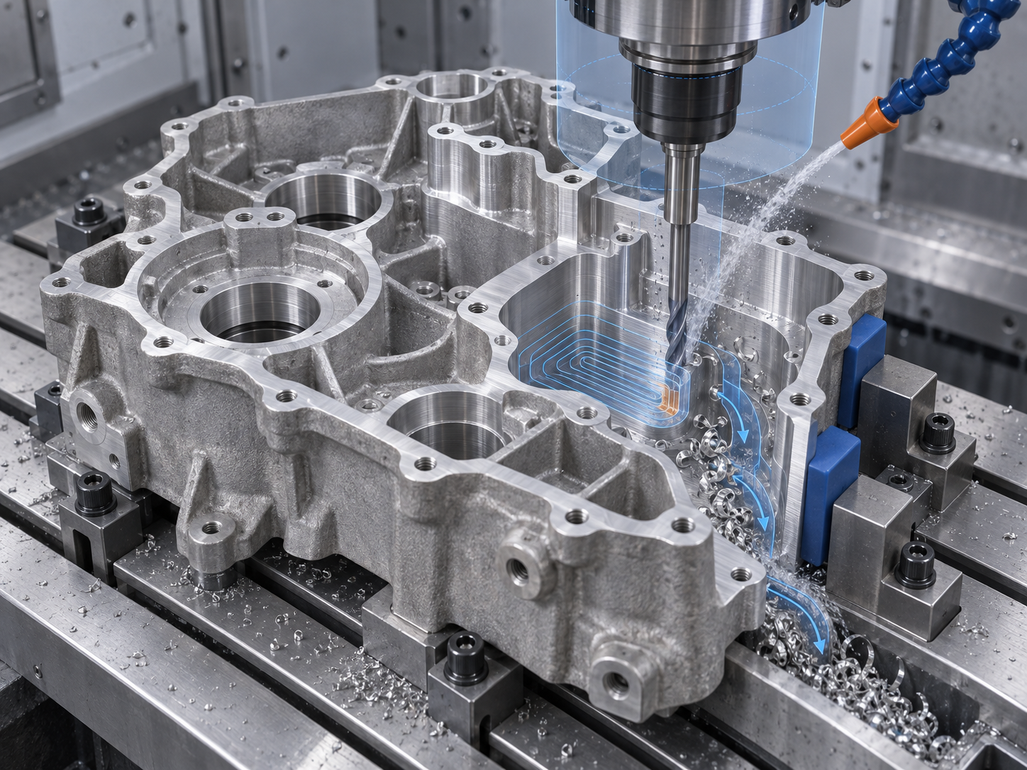
The main constraints in deep-cavity machining are usually not whether the program can be generated, but the reduced rigidity and increased vibration caused by tool overhang, along with difficult chip evacuation. In the process, a shorter, more rigid tool can first remove most of the allowance, after which a longer tool can be selected according to the cavity depth and corner dimensions to complete rest machining and finishing. Feed rate, depth of cut, and cutting load must be adjusted in consideration of the material, tool, and machine-tool rigidity. Before machining, interference among the tool, tool holder, fixture, and cavity wall should be checked. Actual travel and chip evacuation conditions should also be verified on site.
Machining thin-wall box-type parts: gradually release the allowance and clamping forces
Thin-wall areas are prone to deformation caused by cutting forces, clamping pressure, and internal material stresses. When machining box-type parts, it is generally inadvisable to remove all the allowance at once. Instead, a reasonable finishing allowance should be retained, and the material should be released gradually through layered, symmetrical, or alternating machining. Clamping points should be close to the support locations to prevent the fixture from directly deflecting the thin wall; auxiliary supports may be used when necessary. After rough machining, the condition of the part should be observed before deciding whether stabilization treatment is needed or whether the finishing sequence should be adjusted.
FAQ: Frequently asked questions about process selection for box-type part machining
There is no fixed answer for machining box-type parts that is independent of the drawing and part structure. The selection of equipment and fixtures for ordinary holes, cast boxes, welded boxes, and different production volumes should be determined by considering the material, dimensions, tolerances, fixturing conditions, and inspection requirements.
When machining box-type parts, when is drilling alone sufficient for ordinary holes? When are boring or reaming required?
Drilling is generally used for pilot holes, through-holes, and some threaded holes. If higher requirements apply to hole size, roundness, coaxiality, hole spacing, or surface quality, boring, reaming, or other finishing operations are usually added after drilling. The specific process should be determined according to the drawing tolerances, hole depth, material, and equipment capabilities.
Is aging or stress-relief treatment always required after rough machining a box-type part?
Not necessarily. If a cast or welded box is large, has uneven wall thickness, or carries a high risk of residual stress and distortion, aging, stress relief, or a stabilization hold may be scheduled after rough machining, depending on the material, structure, and machining stability. Whether to use such treatment and which method to choose must be confirmed based on the blank condition and subsequent finish-machining requirements.
How does the machining process route differ between cast and welded boxes?
Cast boxes typically start with blank cleaning, followed by any necessary aging or stabilization treatment, and then machining of datum surfaces, planes, hole patterns, and cavities. For welded boxes, plate cutting, bending, and welding must be completed first, followed, where necessary, by correction, stress relief, or post-weld machining. The two routes cannot be applied interchangeably; the key factors are structural rigidity, welding distortion, and the final assembly datums.
How should fixture and equipment choices be balanced when machining box components in small-to-medium batches versus large-volume production?
Small-to-medium batch production generally places greater emphasis on flexible CNC machining, adjustable fixtures, and limited investment in dedicated tooling. In large-volume production, the investment in dedicated fixtures, special-purpose machines, or automated equipment is more easily amortized. The actual selection should also compare the number of setups, cycle time, inspection methods, product life cycle, and process-change risks; it cannot be decided solely based on batch size.
Key takeaways
- Machining box-type parts should begin by identifying the datum surfaces, guideway surfaces, primary hole systems, cavities, and thin-wall areas, followed by the selection of appropriate processes.
- Milling is primarily used for planes, steps, external profiles, and cavities; drilling is commonly used for pilot holes and bottom holes, while boring, reaming, or grinding provides higher hole accuracy and surface quality.
- A typical process route generally follows the logic of blank preparation and stress stabilization, establishing datums, machining the primary planes and hole systems, processing secondary holes, deburring and cleaning, and inspection.
- Boxes with multiple cavities and deep cavities require simultaneous consideration of tool accessibility, residual-material machining, toolpath sequencing, clamping stability, and the risk of fixture interference.
- Cast machining, sheet bending and welding, and sheet-metal forming are different manufacturing routes. The final choice depends on the material, structure, accuracy, production volume, and inspection requirements.