Why Drone Part Machining Cannot Focus Only on Dimensional Accuracy
Drone parts are not necessarily better when made thinner, and not every dimension needs to be manufactured to an extreme level of precision. Motor mounts, arm joints, and brackets must simultaneously meet requirements for lightweighting, stiffness, vibration, impact, heat generation, and repeated assembly. The core of drone part machining is allocating tolerances to the areas that truly affect function, rather than applying tight tolerances uniformly across the entire drawing.
Functional Datums Determine Tolerances for Drone Part Machining
Take a motor mount as an example. The motor mounting surface must maintain stable contact, the positional relationship of the mounting holes affects motor location, and the bearing seat requires attention to bore diameter, concentricity, and its relationship with the mounting datum. If these features deviate, rotor runout, localized loading, or amplified vibration may occur after assembly. For arm joints, the key considerations are typically hole locations, mating surfaces, and load-bearing sections, rather than any single external dimension. Datums and load paths should be established first, followed by a determination of which dimensions require positional tolerances, flatness, or related fit requirements.
Dimensional tolerances for many conventional CNC features may be approximately ±0.02—±0.10 mm, but this is only a reference for assessing process difficulty. Actual results depend on the part dimensions, material, tooling, clamping, machining sequence, and inspection method. Critical fits cannot be replaced with general tolerance ranges; non-functional cosmetic surfaces should not be assigned excessively tight tolerances without justification. This approach helps avoid unnecessary machining costs and deformation risks while concentrating inspection resources on bearing seats, locating holes, sealing surfaces, and mounting surfaces—the features that truly affect flight stability and assembly reliability.
Which Drone Parts Are Suitable for CNC Machining
Drone part machining is common in R&D scenarios involving low volumes, varied part types, and multiple mounting interfaces. CNC machining is suitable for planes, cavities, holes, threads, and curved surfaces in metals or engineering plastics, but process selection should be based on load-bearing and assembly relationships rather than simply pursuing higher accuracy. For a motor mount, the datum relationships among the motor mounting surface, bearing seat, and locating holes should be established first. For an arm joint, hole locations, cross-sectional stiffness, and fatigue loads should be checked together.
| Part | Primary Risks | Suitable Process | Design Reminders |
|---|---|---|---|
| Motor Mount | Uneven mounting surface and misalignment between the bearing housing and motor hole pattern | Milling, drilling, and precision boring | Clearly define datum references, flatness, and hole-position requirements, and avoid assigning extremely tight tolerances to non-functional cosmetic surfaces |
| Arm Connector | Accumulated hole-position errors, thin-wall deformation, and stress concentration | Three-axis or multi-axis milling, drilling, and tapping | Retain continuous load-bearing sections, provide parallel support surfaces for the fixture, and reduce the number of setups where necessary |
| Gimbal Bracket | Uneven mass distribution, insufficient stiffness, and unstable rotary-axis fit | Milling, turning, and precision machining | Balance hollowed-out areas with wall thickness, reinforcing ribs, and dynamic balance; define separate requirements for the rotary-axis hole and mating surfaces |
| Payload Bay Housing | Deformation of sealing surfaces, insufficient heat dissipation, and interface misalignment | Milling, drilling and tapping, and localized precision machining | Use clear datum references for sealing surfaces, connector interfaces, and heat-dissipation surfaces; ensure tool access to internal cavities |
| Landing Gear | Landing impact, localized cracking, and assembly loosening | Milling, turning, or sheet-metal forming | Arrange fillets and reinforcing structures according to the load path; do not rely simply on thinning the part to reduce weight |
| Connector housing | Small-hole blockage, thread burrs, and insertion-positioning deviations | Precision milling, drilling, and tapping | Standardize hole diameters and threads wherever possible, and check the effective length, hole-mouth chamfer, and insertion datum |
Five-axis machining may reduce part flipping and datum changes in arm joints and gimbal supports with inclined surfaces, complex curved surfaces, or multi-face mounting features, but it does not automatically resolve tool accessibility, fixture stability, or inspection issues. The final solution still depends on the material, quantity, structural rigidity, and drawing requirements.
How are common CNC processes divided for drone-part machining?
Drone-part machining processes should not be selected solely on the basis that “higher precision is always better.” First consider the part’s geometric features, load direction, assembly datums, and inspectability, then determine whether milling, turning, or multi-axis machining is appropriate.
| Process | Primary geometric features addressed | Typical parts | Design and process limitations |
|---|---|---|---|
| Three-axis or multi-axis milling | Planes, cavities, ribs, steps, and mounting surfaces | Motor mounts, arm joints, and gimbal brackets | For deep cavities, thin walls, and internal corners, consider tool diameter, length, and chip-evacuation space |
| Turning | Shafts, sleeves, cylindrical interfaces, and surfaces of revolution | Rotating shafts, shaft sleeves, and circular connectors | The axial datum, fit relationship, and clamping location must be clearly defined |
| Drilling and Tapping | Connection Holes, Locating Holes, and Threaded Holes | Arm Joints, Housings, and Connector Enclosures | Hole spacing, hole depth, effective thread length, and hole-mouth burrs directly affect assembly |
| Five-Axis Machining | Angled Surfaces, Complex Contoured Surfaces, and Multi-Face Mounting Features | Load Mounts and Complex Arm Joints | May reduce the need for repositioning and datum re-establishment, but tool accessibility, fixturing, and inspection methods must still be verified |
Five-axis machining is not a label that “automatically delivers higher precision.” For holes oriented in multiple directions or continuous contoured surfaces, it may reduce the number of re-fixturing and alignment operations. If the part can be machined using standard tools and stable datums, three-axis or multi-axis milling may instead be easier to plan, inspect, and reproduce. Process selection also depends on the material, quantity, wall thickness, and stock condition.
Post-Processing of Drone Parts Cannot Conceal Upstream Defects
Deburring should focus on locating holes, threaded holes, sealing surfaces, and mating surfaces, rather than only treating externally visible edges. Before surface treatment, confirm that hole diameters, hole locations, flatness, and assembly datums already meet drawing requirements. Anodizing or other treatments may alter the surface condition; specific coating thickness, color, and functional requirements should be based on the drawing and project specifications. For CNC drone parts, the process chain must ultimately be closed-loop validated through dimensional inspection and actual assembly verification.
DFM Design Checkpoints for Drone Part Machining
In a DFM review for drone part machining, the focus is not on tightening every dimension, but on confirming whether the tooling, fixturing, and inspection methods can support the part's function. The review should begin with wall thickness, hole locations, internal corners, datums, and the fixturing sequence, followed by determining which surfaces require tight tolerances.
Check Thin Walls, Internal Corners, and Tool Accessibility First
Thin-wall structures are prone to deformation under clamping and cutting forces. If a motor mount or arm joint has thin walls, add parallel clamping surfaces or auxiliary supports, or adjust the roughing and finishing sequence to avoid machining directly to the final wall thickness in a single operation. Deep holes also require verification of tool rigidity, chip evacuation, and cooling conditions. Internal right angles generally cannot be machined directly with cylindrical cutters; provide sufficient access space for the tool or change the design to a manufacturable internal corner radius. If the structure does not permit this, evaluate splitting the part or converting it into an assembly.
Specify Hole Diameters, Tolerances, and Datums as Actionable Requirements
Connection holes, locating holes, threaded holes, and bearing seats should not be specified using only isolated dimensions. Drawings should define hole spacing, positional relationships, datums, and effective thread length. Where standard hole diameters can be used, avoid nonstandard small holes and excessively deep, narrow holes whenever possible. Sealing surfaces, mounting surfaces, and bearing fits should each have their functional requirements defined separately. Non-critical cosmetic surfaces can use general tolerances to avoid applying excessively tight tolerances to every surface, which increases machining and inspection burdens.
| Common Errors | Possible Consequences | Corrective Actions |
|---|---|---|
| Thin walls lack a supporting surface | Dimensions spring back after clamping, causing gaps or interference during assembly | Increase the clamping area, use soft supports, and leave critical surfaces for subsequent finish machining |
| There is no space for the tool to enter or exit the internal cavity | Tool collisions occur, residual material cannot be removed, and the actual shape deviates from the model | Increase the machinable fillet radius, open up the tool path, or split the structure |
| Extremely tight tolerances are specified for all surfaces | Machining time and inspection requirements increase, while the performance of non-functional surfaces remains unimproved | Concentrate tolerances on locating holes, bearing seats, sealing surfaces, and mounting surfaces |
Finally, check the number of setups. Parallel clamping surfaces, clearly defined primary datums, and fewer part flips help reduce datum-conversion errors. For complex multi-sided parts, multi-axis machining may be evaluated, but fixture obstruction, tool accessibility, and subsequent inspection methods must still be confirmed. DFM conclusions should be incorporated back into the 2D drawings rather than remaining only in 3D model review records.
How to Select Aluminum Alloys, Titanium Alloys, and Engineering Plastics for Drone Component Machining
Material selection for drone component machining should not be based solely on whether a material is "aerospace-grade" or on strength rankings. First determine whether the part is load-bearing, whether it contacts a heat source, and whether electrical insulation is required, then establish the priorities among weight, stiffness, corrosion resistance, and machinability. Using the same material for a motor mount, gimbal bracket, and connector housing can produce completely different results.
Aluminum Alloys Suit Lightweight Structures, but Stiffness and Heat Dissipation Require Attention
Aluminum alloys are commonly used for motor mounts, arm connectors, brackets, and payload-bay housings because of their relatively low density and good machinability. Weight can also be reduced through structural pockets, ribs, and localized thickening. During material selection, however, mounting-surface stiffness, thread durability, corrosive environments, and surface-treatment requirements must still be checked. Thin-walled aluminum parts may deform during clamping or cutting if they lack supporting surfaces. Treatments such as anodizing may also affect dimensions, hole entrances, and fit relationships, so the treatment condition should be specified on the drawing.
Titanium Alloys and Engineering Plastics Must Be Selected According to Function
Titanium alloys may be suitable for high-load connectors, corrosion-resistant components, or high-strength structures in space-constrained applications. However, cutting loads, heat dissipation, tool wear, and clamping stability require separate evaluation; the decision should not be based solely on a strength label. Engineering plastics are suitable for insulating components, lightweight housings, guards, and non-primary load-bearing parts. Before selecting a material, verify the temperature range, moisture absorption, creep, impact performance, and service life under repeated thread assembly. For drone component machining, the material grade, heat-treatment condition, and stock form should all be confirmed together with the actual load and inspection requirements.
How to Control Deformation and Vibration When Machining Lightweight Drone Components
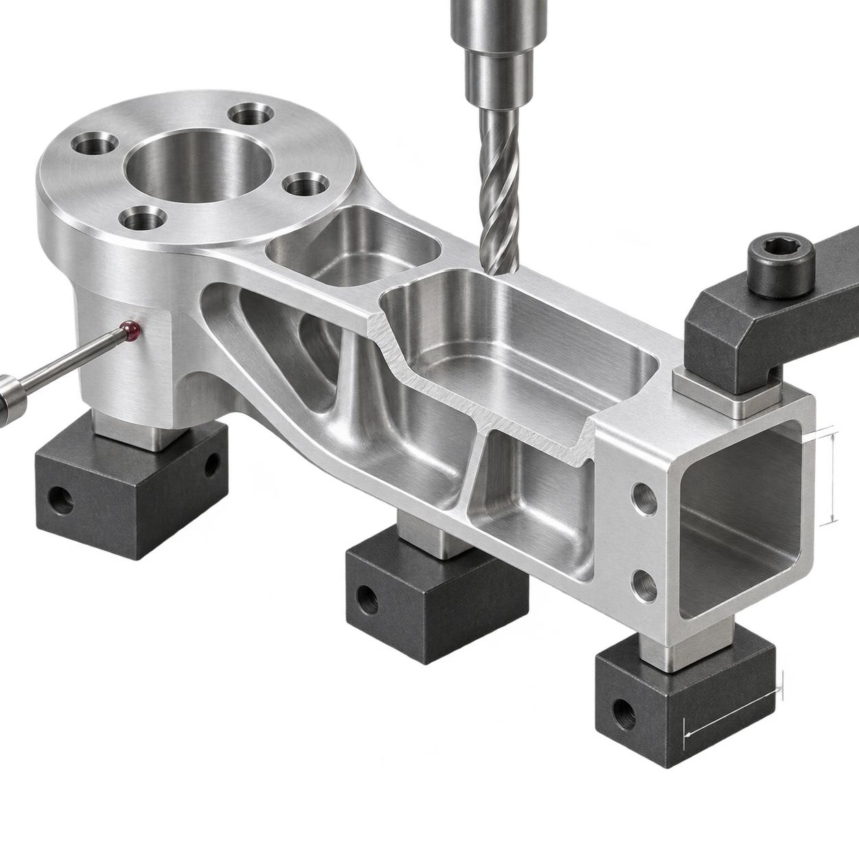
Lightweighting does not simply mean making the walls thinner or removing more material. Pockets, thin walls, and topology optimization reduce local stiffness, making drone components more susceptible to deformation during cutting, clamping, and flight vibration. Excessively sharp rib transitions and sudden changes in cross-section can also create stress concentrations. The design should preserve continuous load paths, arrange wall thicknesses and rib transitions appropriately, and provide parallel, stable support surfaces for the fixture.
The Interaction of Materials, Tools, and Fixturing in Drone Component Machining
The machining plan should treat the material, tools, cutting parameters, cooling and chip evacuation, and fixture as a single process chain. For thin-walled aluminum alloy parts, cutting forces and clamping forces must be controlled. For deep cavities, tool rigidity, entry space, and chip-evacuation paths must be confirmed; engineering plastics require attention to heat buildup and localized melting. For arm joints or lightweight brackets, most of the stock can first be removed during rough machining, followed by semi-finishing and finishing, to avoid removing too much material in a single operation and causing residual-stress relief or structural springback. The fixture must secure the part without clamping weak areas that will lose support after machining.
Toolpaths also affect vibration. The cutting load should be kept as steady as possible, while avoiding sudden changes in direction, long tool overhangs, and continuous cutting in unsupported areas. After machining, do not check only whether the part’s weight has been reduced; also inspect the flatness of mounting surfaces, hole-to-hole relationships, and critical datums. When necessary, verify in the actual assembled condition whether the motor mount, connector, or bracket exhibits interference, looseness, or uneven loading. Lightweighting is a truly effective solution for drone part machining only when it does not compromise stiffness, assembly, or vibration performance.
How to Inspect, Deliver, and Prepare Documentation for CNC-Machined Drone Parts
Delivery of machined drone parts should not be judged solely by whether the part has been “made”; it must also be confirmed that the part can be assembled according to the design datums and operate reliably. It is recommended to establish a closed-loop process in the following order: drawing and 3D model review → material and stock verification → fixturing and datum planning → rough machining → semi-finishing/finishing → deburring and surface treatment → dimensional and assembly inspection. If the front-end datums are not clearly defined, individual dimensions may still pass inspection while problems such as motor eccentricity, misaligned arm hole locations, or poor housing sealing occur.
- [object Object]
- [object Object]
- [object Object]
Before requesting a quotation or starting prototyping, prepare at least the 3D model, 2D drawing, material and heat-treatment requirements, critical dimensions and datums, surface treatment, quantity, operating conditions, assembly relationships, and inspection report requirements. If the part is a motor mount, gimbal bracket, or arm connector, also identify the locating surfaces, hole patterns, and load-bearing interfaces with adjacent components. This enables the machining engineer to assess tool accessibility, fixturing, and inspection methods before quoting, rather than estimating the process based solely on the external shape.
Common Issues in CNC Machining of Drone Parts
The processes, tolerances, and material choices for machining drone parts should all be based on the part’s function, loading conditions, assembly relationships, and actual inspection methods. The following addresses four common engineering questions.
Is Five-Axis Machining Required for All CNC-Machined Drone Parts?
No. Planes, cavities, mounting holes, and conventional ribs can generally be machined using three-axis or other suitable milling processes, depending on the structure. Five-axis machining is better suited to inclined surfaces, complex curved surfaces, and features mounted on multiple faces. When the geometry is suitable, it may reduce the need for repositioning and datum changes, but tool accessibility, fixture stability, part size, and inspection methods must still be considered.
How Can Lightweight Thin-Walled Drone Parts Be Prevented from Deforming During Machining?
Reducing wall thickness alone is not enough. The design should retain a reasonable wall thickness and smooth transitions to reinforcing ribs, avoid abrupt changes in cross-section, and reserve support surfaces for the fixture. From a process perspective, the sequence of rough machining, semi-finishing, and finishing should be arranged appropriately, while cutting force, clamping force, chip evacuation, and heat are controlled. Flatness, hole locations, and the assembled condition must also be inspected after machining. The actual solution depends on the material, structure, and fixturing method.
Can the Tolerance Range of Standard CNC Machining Replace the Fit Tolerances for a Motor Mount or Bearing Seat?
No. The dimensional tolerance of many conventional CNC features may be on the order of approximately ±0.02—±0.10 millimeters, but the actual result is affected by the part size, material, tooling, fixturing, and inspection method. Critical features such as motor mounting surfaces, bearing seats, locating holes, and sealing surfaces should have their datums, fits, positional relationships, and necessary geometric tolerances clearly specified on the drawing. They cannot be replaced by a general tolerance range.
What Is Most Commonly Omitted When Submitting Documentation for Drone Part Machining?
Common omissions include critical datums, functional dimensions, material or heat-treatment requirements, surface treatment, effective thread length, assembly relationships, and inspection report requirements. Before submission, prepare both the 3D model and 2D drawing, and specify the quantity, application, critical hole locations, and sealing or sliding surface requirements. For lightweight thin-walled parts, also indicate clamping exclusion zones or permitted support locations so that the machining provider can evaluate fixturing and deformation risks in advance.
Key takeaways
- Drone parts are not necessarily better when made thinner, and not every dimension requires an extreme tolerance; functional datums and load paths determine how precision is allocated.
- Motor mounts require attention to mounting surfaces, bearing seats, and concentricity. Arm joints require attention to hole locations, datum transitions, and fatigue-resistant structures, while housings place greater emphasis on sealing, heat dissipation, and interfaces.
- Five-axis machining is suitable for multi-face features and complex surfaces. Under suitable geometric conditions, it may reduce repositioning and re-alignment, but it does not automatically guarantee accuracy.
- A DFM review should address standard hole diameters, internal corner radii, tool accessibility, clamping surfaces, thin-wall deformation, and critical tolerances, rather than stopping at “structural optimization.”
- Delivery documentation should include 3D models, 2D drawings, material and surface treatment requirements, critical datums, quantity, application, and inspection items.