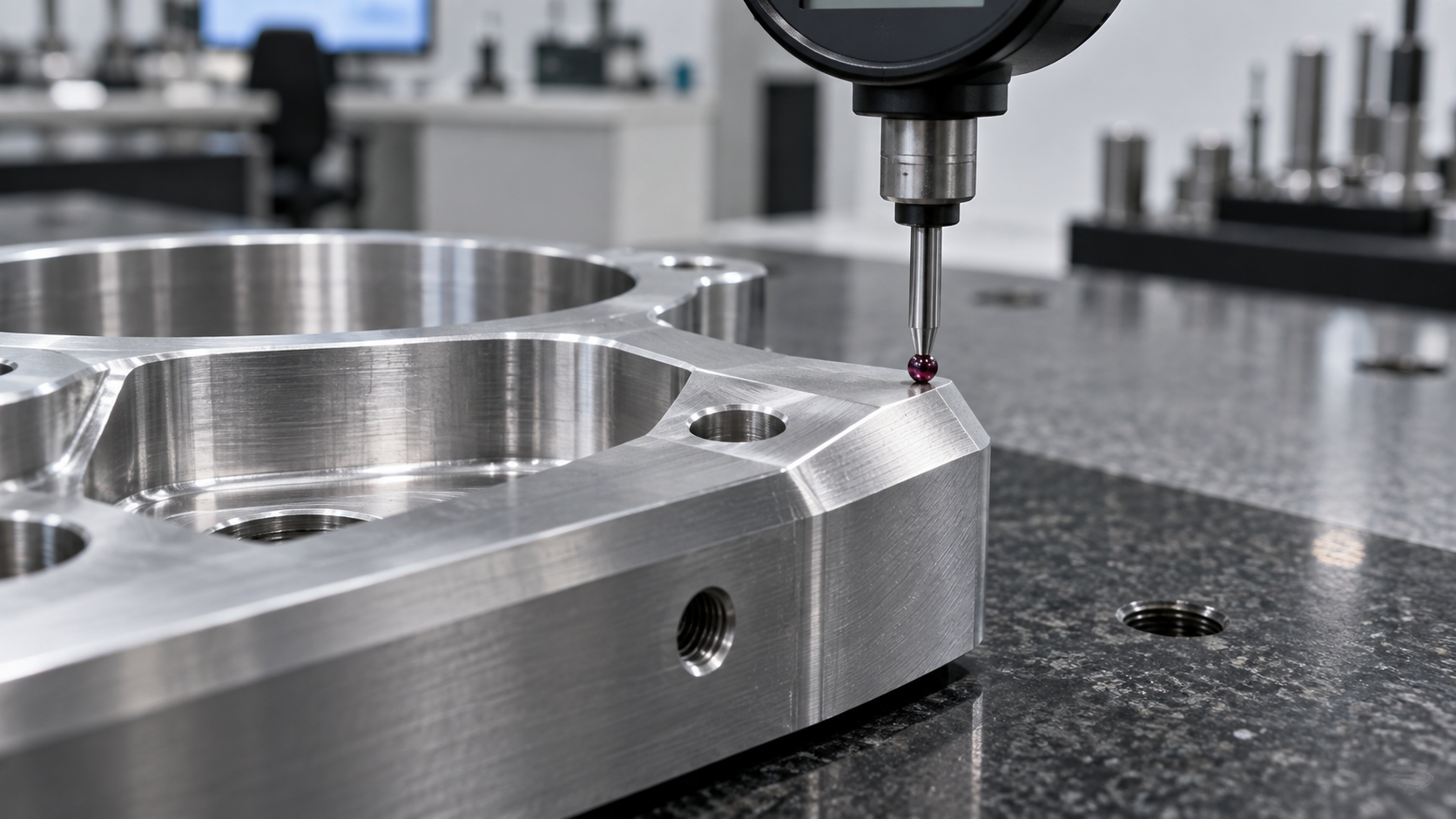
First, see clearly what 0.005mm actually means
Written alone on a drawing, 0.005mm is just a number. On the shop floor, it is the result of a whole set of conditions being satisfied at the same time. First, a few order-of-magnitude conversions: the diameter of a human hair is roughly between 0.05–0.08mm, meaning 0.005mm is about one-tenth of a hair's diameter; ordinary A4 paper is about 0.1mm thick, and 0.005mm is one-twentieth of that. Under the best conditions, the human eye can distinguish a gap on the order of about 0.02mm, so this tolerance is already beyond the range of visual judgment and must rely on gauges and measurement strategy.
More critically, 0.005mm is on the same order of magnitude as common environmental variables. The coefficient of thermal expansion of aluminum is about 23×10⁻⁶/℃; for a 100mm-long aluminum part, a temperature change of 1℃ changes the dimension by about 0.0023mm; a change of 2℃ is already close to 0.005mm. The coefficient of thermal expansion of steel is about 11–12×10⁻⁶/℃; at the same length, 1℃ brings about a 0.0011mm change. This means that if the workshop temperature fluctuates by several degrees over the course of a day, the part dimensions themselves are drifting, and both machining and measurement will be affected.
Why it is a system problem, not a single-machine problem
Many people's first reaction is to "find a high-precision machine tool." Machine tool geometric accuracy is indeed an entry condition, but it only determines the upper limit of theoretical capability. What truly determines whether a part can stably fall within 0.005mm is the accumulation of errors at every link in the following chain: whether the drawing definition is clear, whether the process route is reasonable, whether fixturing introduces deformation, whether cutting heat and spindle thermal elongation are controlled, whether the ambient temperature and vibration are stable, and whether the uncertainty of the measurement system itself is small enough. If any link is out of control, the final dimension will drift out of the window.
There is also an easily overlooked fact: measurement itself has uncertainty. The resolution of a gauge is not equal to its measurement capability; temperature, measuring force, fixturing method, and operator technique all contribute error. If the measurement uncertainty is on the same order of magnitude as the tolerance band, then "measured as qualified" does not equal "actually qualified." Therefore, machining to 0.005mm is essentially a controlled system, not the single-point performance of a particular piece of equipment.
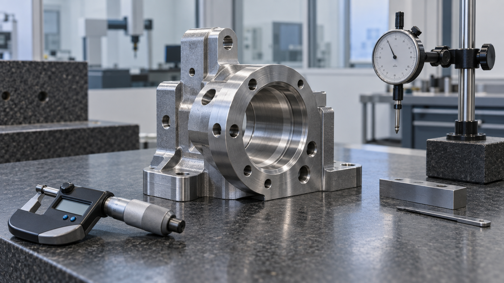
The following content unfolds along this chain: from drawing annotation and the datum system, to machine tools and cutting tools, heat and vibration, fixturing and process routing, and then to the closed measurement loop and on-site troubleshooting. Each section revolves around the same question—which variables must be identified, quantified, and controlled. For situations where the feasibility of a specific part needs to be evaluated, you can first upload the drawing through AI chat quotation and let the engineering side make an initial manufacturability judgment.
Drawing stage: how tolerances are specified determines whether it can be made later
Many out-of-tolerance disputes do not happen on the machine tool, but on the drawing. A vaguely annotated drawing quietly shifts judgments that should be borne by the design side onto the workshop: the operator can only guess from experience which face is the datum, which location is the mating surface, and which dimensions really need to be held. At the 0.005mm level, the cost of guessing wrong is directly magnified into scrap.
Datum system: first define "where to measure from," then discuss "how accurate to make it"
The first issue for micron-level parts is not machining, but datum consistency. If the design datum, machining datum, and measurement datum are not on the same chain, then no matter how tight the tolerance is, it is only a number on paper. A common practice is to choose a face with sufficient area and sufficient rigidity as the primary datum, and avoid using a raw casting surface or a thin-wall edge as the datum—these faces themselves will deform due to clamping force and residual stress.
A more practical judgment is: write the key dimensions as a clear tolerance chain, starting from the functional face and annotating level by level to the locating face, rather than scattering unilateral tolerances across multiple views. Once the chain is clear, the workshop knows which dimensions must be guaranteed in a single setup and which can be completed in separate operations.
GD&T is not decoration: it determines the gauge and measurement plan
On micron-level parts, geometric tolerances (flatness, parallelism, coaxiality, position) are often more critical than dimensional tolerances, because they describe functional relationships. When specifying position tolerance, if the datum and maximum material requirement are given at the same time, the inspection side can use a functional gauge for quick judgment; conversely, if only an isolated dimensional tolerance is written, the measurement side can only indicate point by point, which is inefficient and prone to disputes.
It should be noted that GD&T annotation must match measurement capability. If the drawing requires a certain geometric tolerance but the factory does not have the corresponding measurement means or datum establishment method, this requirement cannot be verified. The value of a design for manufacturability (DFM) review at this stage is precisely to put "can it be measured" and "can it be made" on the table together in advance.
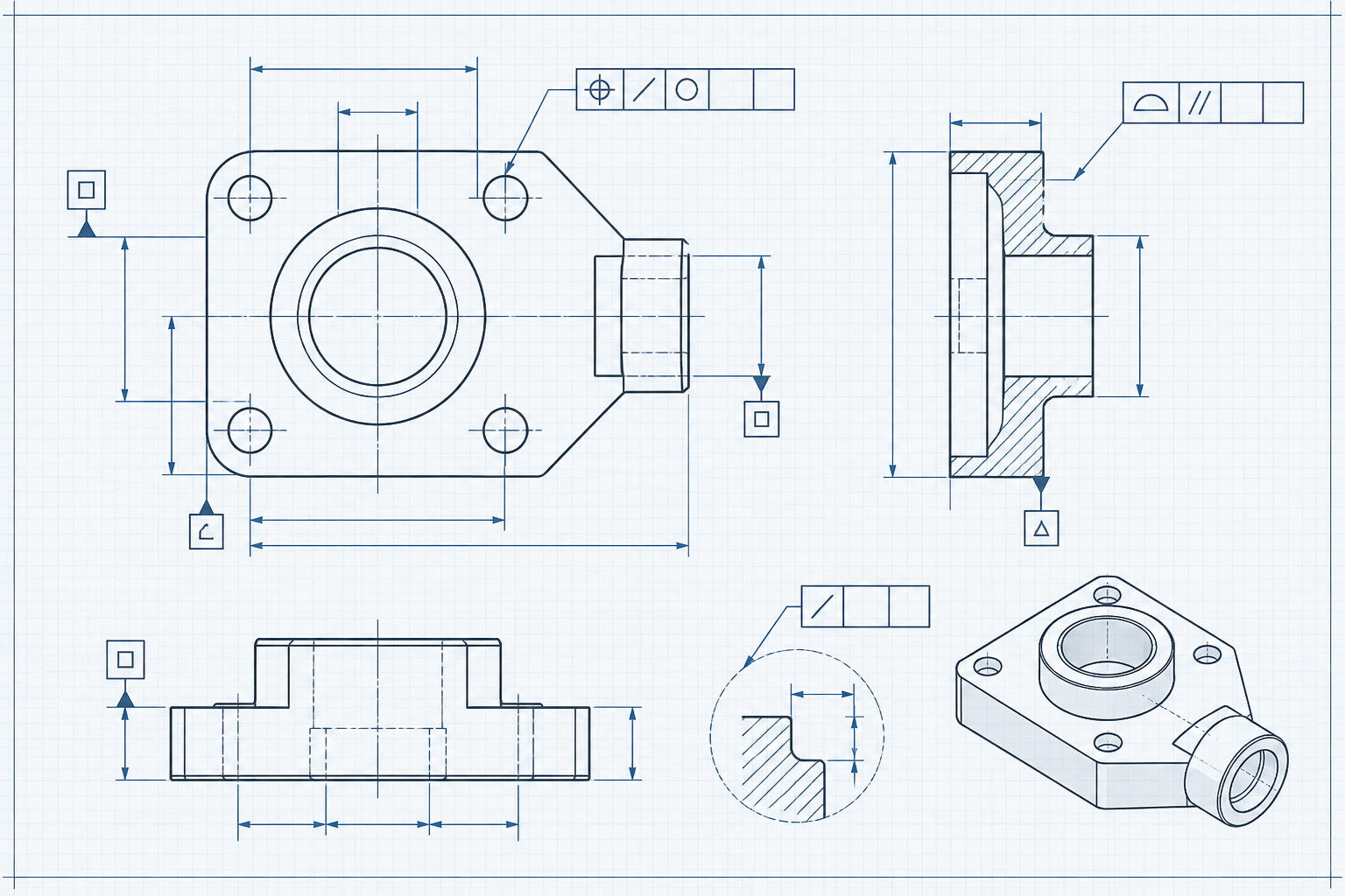
Only when the drawing information is complete and the datums are clear does the subsequent process discussion become meaningful. For parts requiring precision fits, you can first learn about the achievable machining range through CNC machining capabilities, and then decide which features to leave for subsequent finishing.
Machine tools and cutting tools: capability is the starting point, not the answer
Many RFQs include the line "Equipment requirement: imported high-precision machine tool." This statement itself is not wrong, but it oversimplifies the problem. A machining center with a high nominal positioning accuracy, placed in a constant-temperature workshop, using suitable cutting tools, and programmed by someone familiar with the material, is indeed more likely to achieve micron-level results; but the same machine tool, if tool runout is too large, cutting parameters are aggressive, and cooling is insufficient, will still stably produce out-of-tolerance parts. Equipment capability determines the "theoretical upper limit"; process strategy determines the "actual landing point."
Machine tool geometric accuracy and thermal stability
The geometric accuracy of a machine tool includes guideway straightness, perpendicularity of each axis, spindle rotational accuracy, and so on. These errors are often masked in single-piece machining, but in batch or long-cycle cutting they appear as drift. More critical is thermal accuracy: after continuous spindle operation, temperature rise causes axial elongation, and the ball screw also changes the actual pitch when heated. For a target on the order of 0.005mm, starting roughing directly on a cold machine and not performing thermal balance before finishing is a common starting point for failure. A prudent approach is to let the machine tool idle at the expected speed for a period of time, and only enter the finishing operation after thermal deformation has stabilized.
Tool runout, wear, and cutting force
The cutting tool is the link that directly contacts the workpiece, and its condition deserves more attention than the machine tool nameplate. If there are contaminants on the mating surface between the tool holder and the spindle, or if the collet clamping position is incorrect, radial runout will be amplified; once runout is large, the actual cutting depth of the cutting edge becomes uneven, and both dimensions and surface quality are affected. Tool wear is a gradual process: flank wear increases cutting force, causing elastic deflection in thin-walled parts, and the dimension springs back after release. For precision-sensitive features, it is usually necessary to confirm the tool wear condition before finishing, and if necessary replace it with a new tool or take a separate finishing pass.
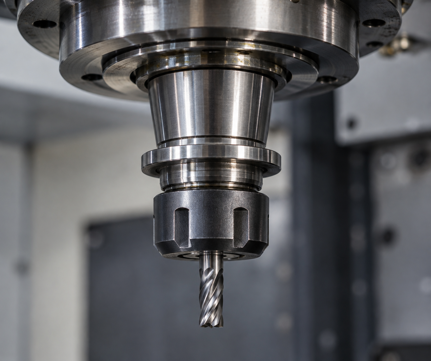
Therefore, an equipment list can only answer "is it possible," not "can this batch be produced stably." What really needs to be confirmed is: whether the machine tool is in good maintenance condition, whether there is a thermal balance procedure, whether tool management is standardized, and whether the programming strategy leaves margin for precision. These things are not written in the equipment model, yet they directly determine the result. If you are evaluating a precision-sensitive project, you can first send the drawing and key features to the engineering team for a manufacturability judgment, and then decide the process route, rather than locking in the equipment model first.
Heat and Vibration: The Most Easily Overlooked Variables in Micron-Level Machining
Many shops have seen this scenario: the first part passes inspection in the morning, fails on recheck at noon, and passes again in the afternoon. The operator didn't change the program, the tool wasn't replaced, and the machine didn't alarm—only the environment changed. When the tolerance band is only 0.005mm, heat and vibration are no longer "background noise" but input variables that directly participate in the formation of dimensions. Rather than "tolerating" them as disturbances, it's better to "manage" them as process parameters.
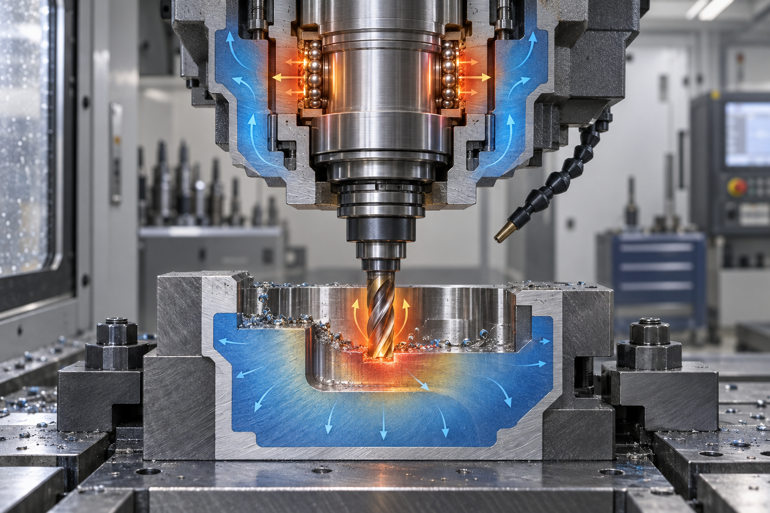
Temperature: From Shop Air to Spindle Growth
The effect of heat on dimensions can be estimated with a simple relationship: ΔL = α · L · ΔT. The coefficient of linear expansion of steel is on the order of about 11–12 ×10⁻⁶/℃, meaning that for a 100mm steel part, a 5℃ temperature change produces roughly 5–6μm of drift in the length direction—already on the same order as 0.005mm. Aluminum has a higher coefficient and is even more sensitive to temperature. This means: if the shop temperature fluctuates by a few degrees over the course of a day, discussing whether "the machine's accuracy is sufficient" is actually meaningless.
Heat sources are not limited to ambient air. A spindle running continuously generates heat and grows along the Z axis; ball screws and guideways also heat up from friction; the cutting zone itself generates a large amount of heat, and coolant flushing brings localized rapid cooling. These heat sources have different time constants: ambient temperature is measured in hours, spindle thermal growth may change rapidly within the first few tens of minutes, and cutting heat is nearly instantaneous. The result is that parts are "frozen" in different thermal states at different points in time.
- Constant temperature and thermal equilibrium: For micron-level tasks, bringing the machine and workpiece to thermal equilibrium before machining is often more effective than pursuing more expensive equipment. Running the machine idle for a period after startup before touching off is the lowest-cost means of thermal stabilization.
- Reduce heat input: Select cutting parameters and cooling methods sensibly to avoid long periods of heavy-load cutting that pile heat into the workpiece and spindle.
- Measurement also requires temperature control: When the temperature difference between the gauge and the workpiece is too large, the measurement result itself is drifting; see the measurement closed-loop section later for details.
Vibration: The Transmission Chain from Foundation to Tool Tip
Vibration affects accuracy in two ways: one is causing chatter marks on the surface and worsening roundness; the other is more insidious—it makes the relative position between tool and workpiece slightly different on every revolution, ultimately showing up as dimensional scatter. Vibration sources may come from a neighboring press, an overhead crane, or a forklift, or from the machine tool's own imbalance or excessive tool overhang.
The engineering approach is to handle it in layers: vibration isolation (machine damping pads, independent foundations, keeping away from impact equipment), rigidity (shortening tool overhang, choosing more rigid tool holders, reducing slender bar stock), and process (adjusting spindle speed to avoid chatter regions, controlling depth of cut and feed). Of these three, process adjustment often takes effect fastest because it doesn't require changing hardware.
It should be noted that heat and vibration rarely appear alone. Cutting heat changes the local stiffness of the material, vibration exacerbates tool wear, and wear in turn increases cutting force and heat. They are a coupled system, so during on-site troubleshooting don't expect to completely solve the problem by changing only one variable at a time—but changing only one variable at a time is still the fastest path to finding the main cause. For parts that require stable micron-level results, it is recommended to include temperature control, fixturing rigidity, and the measurement environment in the discussion during the process review stage, rather than going back to patch things up after the first part fails inspection. If you are unsure whether a certain structure is suitable for the CNC route, you can first learn about the applicable boundaries through the CNC machining capabilities page, and then decide on the process plan.
Fixturing and Process Routing: Keeping the Part Stable During Machining
Many micron-level out-of-tolerance issues are not because the machine "can't make it," but because the part is repeatedly pushed around among the three actions of clamping, cutting, and releasing. Clamping force bends a thin wall, and as soon as the tool passes, the material springs back; release the jaws, and the part springs back to yet another shape. The dimension you see during measurement is actually the difference between the "free state" and the "clamped state." To reliably achieve results at the 0.005mm level, process routing and fixturing strategy are often more critical than switching to a more expensive machine.
Datum Consistency: Don't Let the Part "Change Coordinate Systems" Between Operations
If the design datum, process datum, and measurement datum on the drawing each speak a different language, the tolerance chain gets amplified once in every operation. A workable approach is to make the three coincide as much as possible: in the first operation, machine a reusable locating surface or process boss, and use it as the datum for subsequent operations rather than re-aligning each time. For parts requiring machining on multiple faces, prioritize completing as many features as possible in a single setup to reduce the number of flips—each flip introduces one more locating error and one more clamping deformation.
Flexible Clamping and Support: Distribute the Force, Don't Concentrate It
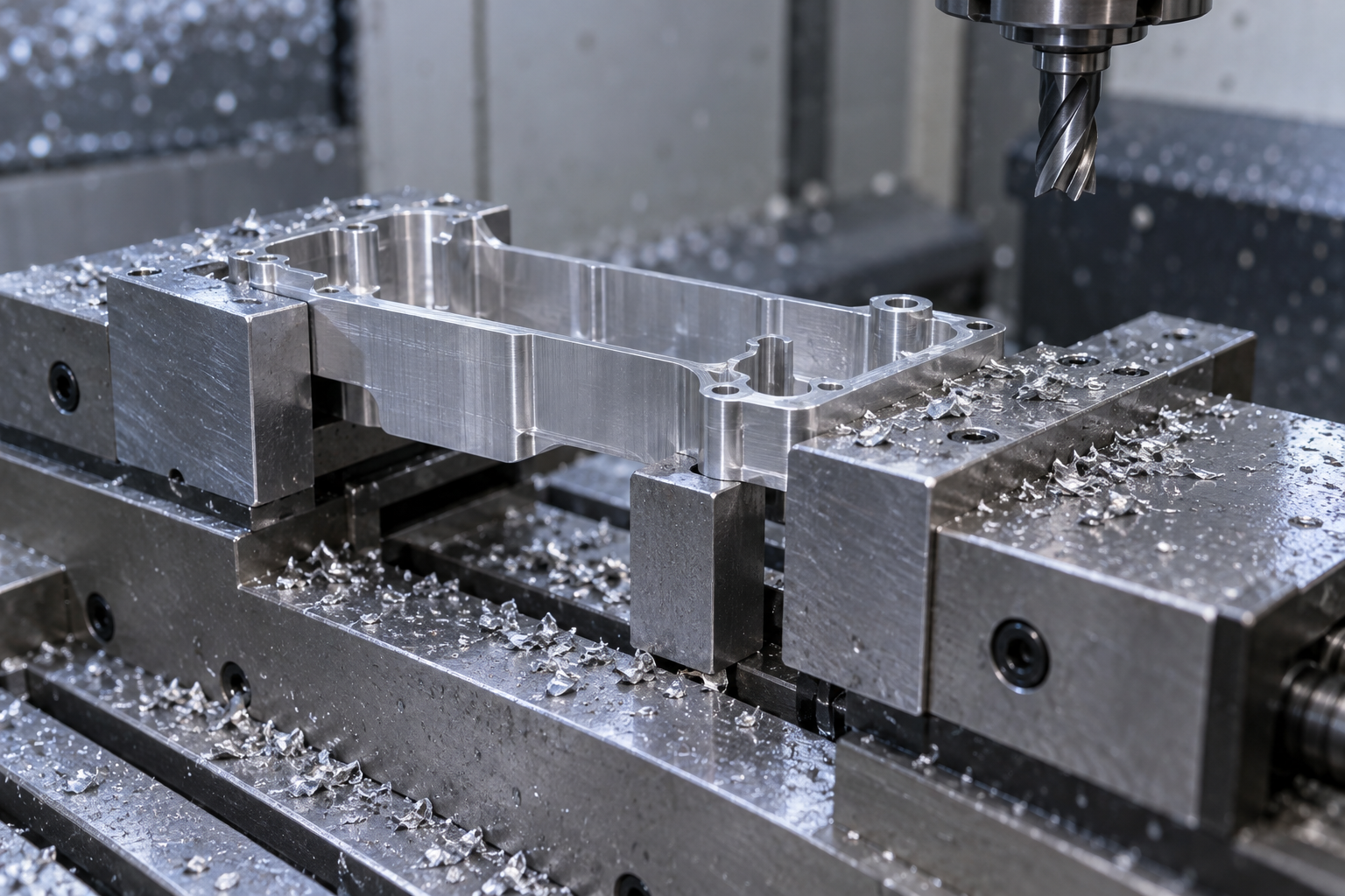
Thin-walled parts, slender shafts, and frame-type parts are most vulnerable to point-contact hard clamping. Common engineering approaches include: using soft jaws or dedicated contoured fixtures to increase contact area; using vacuum chucking, wax fixturing, or low-melting-point alloy filling to provide uniform support; adding a steady rest or auxiliary support for slender parts to shorten overhang. The direction of clamping force is also worth considering—try to apply clamping force in regions with better rigidity and avoid pressing directly on the thin wall to be machined. When necessary, you can clamp lightly first, then add clamping after rough machining, trading "staged clamping" for controllable deformation.
Stress Relief and Operation Sequence: Release Deformation in Advance
Residual stress inside the blank and cutting stress generated by rough machining will both be released during finish machining or after the fixture is released. Common countermeasures are: arrange a stress-relief operation between rough and finish machining (such as natural aging or stress-relief treatment; the specific method must be confirmed with engineering); use small depths of cut and multiple passes for finishing to avoid removing all the allowance in one go; remove material symmetrically so that stress release is as balanced as possible. For parts with high accuracy requirements, finishing is sometimes performed in a near-constant-temperature environment, with a stabilization period left after machining before measurement.
The process routing itself is also a form of "accuracy allocation." Put the most critical dimensions in the last and most stable operation, and have the preceding operations only responsible for leaving the allowance evenly. In this way, even if small fluctuations occur midway, they will not directly eat into the final tolerance. For your specific part, you can submit the drawing and critical dimensions for engineering evaluation to confirm whether the fixturing plan and operation sequence match, and then decide whether dedicated fixtures are needed.
Measurement Closed Loop: Without Trustworthy Measurement, There Is No Reproducible Accuracy
The most dangerous sentence in a shop is "I measured it, it's fine." The problem is: what did you measure with, at what temperature did you measure, and did you measure the element the drawing actually requires. When the tolerance band is only 0.005mm, measurement itself also becomes a micron-level process issue—the indication error of the gauge, the contact force of the probe, the thermal state of the workpiece, and even the hand temperature of the operator holding the probe all enter the final reading. In other words, measurement uncertainty must be significantly smaller than the tolerance band, otherwise you are merely using noise to judge pass/fail.
Gauge Selection: Look at Uncertainty First, Then Resolution
Many people choose gauges based only on resolution. A 0.001mm digital micrometer looks "more accurate" than a 0.01mm caliper, but resolution is only display capability, not measurement capability. To judge whether a gauge is adequate, you need to see whether its measurement uncertainty falls within a reasonable proportion of the tolerance band—the common engineering rule of thumb is that the smaller the gauge uncertainty's proportion of the tolerance band, the better, and the specific proportion should be confirmed with the quality engineer rather than decided arbitrarily.
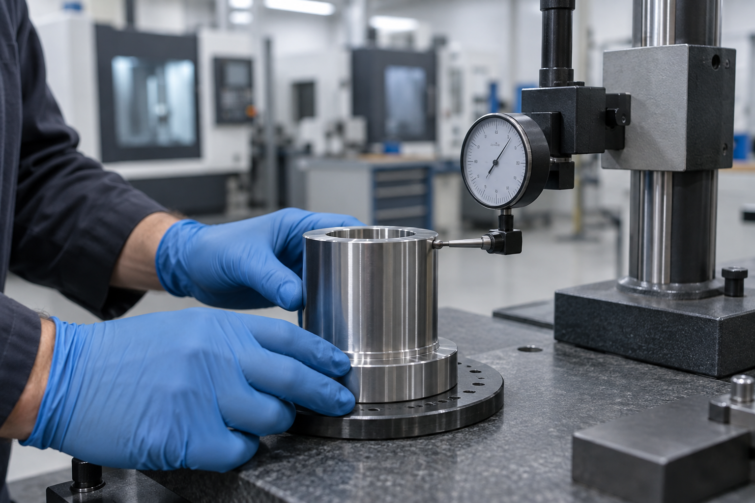
- OD/thickness types: Digital micrometers, lever micrometers, suitable for regular cylinders and flat plates, but pay attention to the flatness of the anvil faces and consistency of measuring force.
- ID/hole types: Inside micrometers, air gauges, plug gauges. Air gauges are sensitive to hole diameter and roundness and are suitable for batch comparison, but require calibration with master parts.
- Form and position: Roundness testers, coordinate measuring machines (CMM), vision measuring machines. Coaxiality, position, and profile in GD&T can basically only be handled by this type of equipment.
- Surface and microscopic: Roughness testers, contour testers, used to determine whether a surface anomaly is a tool problem or a process parameter problem.
- Rapid comparison: Dedicated gauges, go/no-go gauges, suitable for production line takt time, but they can only answer "is it within the band," not "why is it off."
A common misconception is using general-purpose gauges to measure GD&T elements. Calipers cannot measure coaxiality, and micrometers cannot measure position. If the drawing specifies a datum system, the measurement plan must be consistent with the datums; otherwise, no matter how beautiful the data looks, it is meaningless.
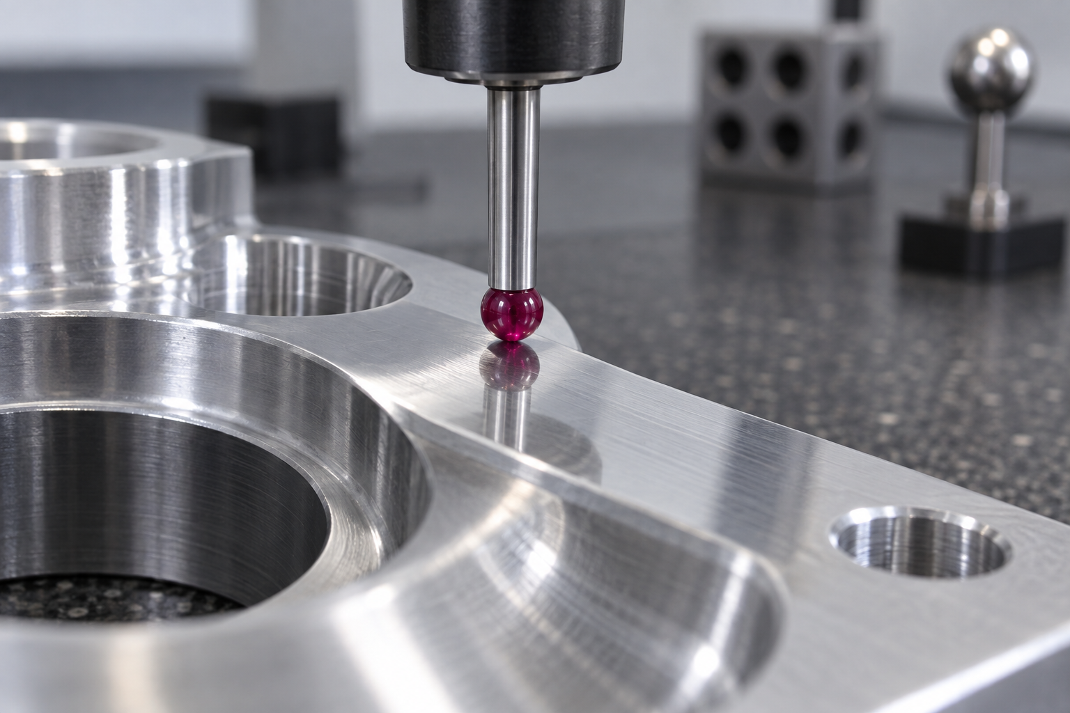
Measurement environment: temperature is the hidden third variable
The coefficient of linear expansion of steel is on the order of 10⁻⁵/℃, which means that for every 1℃ change in temperature, the dimension of a 100mm-long steel part changes by about 1μm or so. For a 0.005mm tolerance band, this magnitude can no longer be ignored. That is why high-precision measurement usually requires a controlled temperature, and readings should be taken only after the workpiece, the measuring instrument, and the environment have reached a consistent temperature—a part that has just come off the machine and still carries cutting heat often measures oversized, then "shrinks" back after cooling, giving rise to the classic contradiction of "passes in production, out of tolerance on re-inspection."
In practice, common approaches include: letting the part equalize in temperature in the measurement room before measuring; avoiding holding the measurement area by hand for extended periods; placing the measuring instrument and the workpiece in the same environment; and recording the temperature at the time of measurement for temperature-sensitive critical dimensions. These actions add little cost but can significantly reduce the misjudgment rate.
From data to process: using measurement results to correct parameters in reverse
The value of a measurement closed loop is not in "judging pass/fail," but in turning deviation into an executable correction amount. If a batch of parts is systematically oversized, possible directions include tool wear compensation, thermal elongation compensation, feed and depth-of-cut adjustment, and estimating springback after clamping release. The key is to distinguish "random fluctuation" from "systematic offset": the former must be addressed through process capability and stability, while only the latter is suitable for parameter compensation.
Finally, accept a reality: a measurement closed loop is not a one-time action, but a continuous process. The same machine and the same fixture may perform differently in different seasons and with different batches of material. Correlating and accumulating measurement data, environmental conditions, and process parameters is the key to turning 0.005mm from "occasionally achieved" into "consistently achieved."
Common failure modes and troubleshooting order
When problems arise in micron-level machining, the worst thing to do is "adjust parameters first." When dimensional drift appears within the same batch of parts, the cause may lie in the machine's thermal state, clamping release, tool wear, or the measurement system itself. The value of on-site troubleshooting is to narrow the range of variables to one or two by the shortest path, rather than overturning and redoing the machine, tool, program, and measuring instruments all at once. The following is organized in the order of "first rule out measurement, then rule out clamping, and finally suspect the machine and process." The logic of this order is that the closer a link is to the part delivery end, the easier it is to verify first, and the easier it is to be overlooked.
Dimensional out-of-tolerance: first ask "was it measured wrong?"
The first suspect for dimensional out-of-tolerance is often not the machine, but the measurement. Whether the measuring instrument is within its calibration validity period, whether the probe is clean, whether the part temperature matches the measuring instrument, and whether the measuring force causes elastic deformation of thin-walled parts—all of these can make readings deviate from the true value. This is especially true for hole diameters and thin-wall dimensions: the measuring force of a contact measuring instrument can be enough to make the reading "look acceptable," yet the part will not fit during assembly. It is recommended to first measure the same part at the same position repeatedly to observe repeatability; if repeatability is poor, solve the measurement system first before discussing machining.
If the measurement is trustworthy, then determine whether the out-of-tolerance is a systematic offset or random dispersion. Systematic offset usually points to tool compensation, thermal drift, or datum conversion errors; random dispersion is more likely due to insufficient clamping rigidity, tool wear, or chip interference. The troubleshooting actions corresponding to the two are completely different, and handling them together will only lead to repeated trial and error.
Poor roundness and cylindricity: rule out layer by layer from spindle and tool to clamping
Poor roundness is common in turning and boring operations. The recommended troubleshooting order is: first confirm whether the part is deformed by clamping (especially obvious in thin-walled sleeve-type parts), then check whether the tool is worn or has built-up edge, and only then suspect spindle rotational accuracy. If the roundness error shows obvious periodic waviness, it is often related to the vibration frequency of the spindle or feed system; if the error is oval or trilobed, it is more likely due to uneven clamping force distribution or release of internal stress in the material. Distinguishing waveform characteristics is more effective than blindly changing tools.
Surface abnormalities: quick judgment of chatter marks, burrs, and burns
If regular chatter marks appear on the surface, first check whether tool overhang is too long, whether the tool holder and spindle taper are clean, and whether cutting parameters fall in a chatter-sensitive zone; if burrs or rolled edges appear on the surface, they are mostly related to tool dulling, excessive feed, or material toughness; if the surface is burned or discolored, it points to accumulated cutting heat, insufficient cooling, or excessive linear speed. Under micron-level requirements, these three types of phenomena often affect dimensions at the same time, so do not focus only on appearance; re-measure critical dimensions at the same time to determine whether it is a "surface problem" or "the appearance of a dimensional problem."
- Step 1: Verify the measurement system. Repeat measurements, change measuring instruments, and change operators to confirm that the readings themselves are trustworthy.
- Step 2: Check clamping and release. Re-measure after releasing the fixture to determine whether there is clamping deformation or stress springback.
- Step 3: Confirm thermal state. Whether the machine is fully warmed up, whether the workshop temperature is stable, and whether dimensions drift in one direction during continuous machining.
- Step 4: Check tool and program. Whether tool wear, tool compensation settings, datum conversion, and tool path meet expectations.
- Step 5: Return to machine geometric accuracy. Only after the first four steps have been ruled out, evaluate the condition of the spindle, guideways, and feed system.
The core of this order is to rule out low-cost, high-probability causes first. The most common mistake on site is to adjust program compensation as soon as out-of-tolerance is seen, thereby "compensating" a systematic offset into random error, making the next batch of parts even less stable. If the problem repeatedly appears on the same feature, it is recommended to record the troubleshooting process to form a reusable judgment path. When specific process capabilities and inspection methods are involved, first confirm with the engineering team before deciding whether the process route needs to be adjusted.
Frequently asked questions (FAQ)
The following are the most commonly asked questions around 0.005mm-level machining. The answers provide only judgment logic and engineering direction, and do not promise specific tolerances, lead times, or prices—these must be confirmed item by item with the engineering team based on part structure, material, and quantity.
If the drawing specifies 0.005mm, does every dimension need to meet this precision?
No. 0.005mm should usually apply only to a few critical mating dimensions; other dimensions can be given reasonable tolerances according to function. If the entire drawing is uniformly specified this way, cost and risk will rise exponentially, because every dimension will consume resources for temperature control, slow feed, and multiple measurements.
It is recommended to confirm item by item during review: if this dimension is out of tolerance, will it affect assembly or function? If not, relax it. Concentrating the budget on the few dimensions that truly determine performance is more cost-effective than tightening everything across the board.
Which materials are easier to machine to 0.005mm, and which are basically unrealistic?
Metals with good dimensional stability (such as common aluminum alloys and some stainless steels) are relatively easy to bring close to this level under controlled conditions; plastics, especially hygroscopic materials or those with a high coefficient of thermal expansion, change dimensions with the environment, making it significantly harder to achieve and maintain 0.005mm. Soft, easily deformable materials introduce errors during clamping and measurement.
When selecting materials, ask two questions at the same time: can it be machined to this level, and can it hold this level in the measurement and assembly environment? To confirm whether a specific material can meet the requirement, check the materials library and then communicate with engineering.
Where does the cost mainly go? Why does the price rise so much when precision is improved slightly?
The bulk of the cost is usually not in the cutting itself, but in temperature-controlled environments, slow finishing, dedicated fixtures, stress-relief processes, and repeated measurement. Each time precision is tightened by one level, the pass rate drops and rework and inspection time increase, all of which add to the unit price.
Therefore, a more effective way to reduce cost is not to push down the unit price, but to reduce the number of features requiring high precision, relax non-critical tolerances, and combine clamping operations. After uploading a drawing, you can quickly understand the magnitude through AI conversational quoting.
How do you confirm that a part truly achieves 0.005mm, rather than relying only on what the machine says?
Rely on a measurement closed loop, not on equipment specifications. It is necessary to select appropriate measuring instruments (such as CMMs and high-precision measuring devices), measure under controlled temperature, and evaluate measurement uncertainty—if the uncertainty of the measurement itself is close to the tolerance band, the conclusion is not trustworthy.
More critically, feed measurement data back into the process: which batch drifted, by how much, and how to compensate. Without this closed loop, precision cannot be reproduced. When necessary, 3D scanning can be combined for overall geometry verification.
Is achieving 0.005mm equally difficult for small batches and large batches?
No. Small batches can approach high precision through single-piece adjustment and manual compensation, but consistency depends on the operator; large batches require the process to remain stable over a long period, and thermal drift and tool wear will accumulate, so process control and regular calibration are necessary to maintain it.
Therefore, for the same drawing, different quantities mean different process routes and risk points. Before scaling up a batch, it is recommended to first run a small-batch validation to confirm whether the process window is wide enough.
Key takeaways
- 0.005mm is system precision, not single-machine precision: the machine tool, cutting tools, fixturing, temperature, and measurement must all be controlled simultaneously.
- The way tolerances are specified determines success or failure: drawings with unclear datums, stacked tolerance chains, and no measurement datum cannot be produced stably even with the best equipment.
- Heat is the biggest invisible variable in micron-level machining; constant temperature, thermal balance, and online compensation are often more effective than changing machine tools.
- Fixturing deformation is often underestimated: for thin-walled and slender parts, the clamping force and support method directly determine which side the final dimension falls on.
- Without a closed measurement loop there is no precision: gauge capability, the measurement environment, and data feedback are the prerequisites for stable reproducibility.



