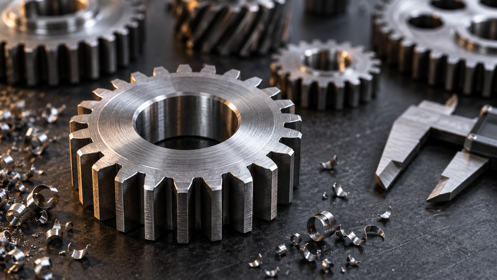
Don't rush to ask "can it be made": the four prerequisite variables of gears
Send the same gear drawing to three suppliers, and quotes range from a few hundred to a few thousand, with lead times from one week to one month. The difference is often not "who is cheaper," but that the two sides' understanding of this drawing is not on the same level at all. Purchasing sees "a toothed disc," while the workshop sees four variables that must be determined first: tooth profile and module, material and heat treatment, batch size, and functional precision requirements. If any one of these four variables changes, the entire process route may be replaced.
Many inquiries get stuck because the drawing only gives geometry and not function. A gear is not a decorative part; its value lies in transmitting motion and torque. Is it low-speed manual adjustment or high-speed continuous meshing? Is it one-way light load or frequent reversing with impact? These determine whether the tooth surface needs grinding, whether the tooth root needs strengthening, and whether the material needs quenching and tempering. If the function is not defined, the process can only be quoted in the most conservative way—conservative means a more expensive route and a longer process chain, while the customer still thinks the other party is "marking up the price."
So the correct order is not "first ask whether it can be made," but first write these four variables clearly, and then let engineering judge which route to take. Tooth profile determines what machine tool is used, material and heat treatment determine the process sequence, batch size determines the unit cost structure, and functional precision determines how tight inspection and fitting should be. The following sections break this down in that order.

Tooth profile determines the machine tool: the boundaries of hobbing, shaping, milling, and wire EDM
When you receive a gear drawing, the first thing to ask is not "can it be made," but "what tooth profile is this." Once the tooth profile is determined, the range of usable machine tools is basically locked in. Gear machining is divided into two major schools: generating machining and form machining. Generating relies on the tool and gear blank continuously rolling together at a fixed transmission ratio, and the tooth profile is enveloped by the tool, so the same tool can machine gears with the same module but different numbers of teeth; form machining directly cuts with a tool whose shape matches the tooth slot, and tooth profile precision depends on the tool itself.
Hobbing and shaping: the two main lines of generating machining
Hobbing is the most common route for external spur and helical cylindrical gears. While the hob rotates, it feeds along the axial direction of the gear blank. It is efficient and versatile; under the same module, changing the number of teeth basically does not require changing the tool, making it suitable for batch production. Its shortcoming is that the tool interferes when machining internal teeth and teeth close to a shoulder, so gears with bosses and cluster gears often cannot be fully hobbed.
Shaping uses a shaper cutter for up-and-down reciprocation plus generating motion, which exactly fills the blind spot of hobbing: internal ring gears, cluster gears, racks, and situations with limited axial space are handled more comfortably by shaping. The cost is that efficiency is usually lower than hobbing, and the tool is also more expensive. Whether to choose hobbing or shaping essentially depends on whether the tooth profile is external or internal, whether there is a shoulder beside the teeth, and whether the batch size is enough to amortize tooling costs.
Milling and wire EDM: the outlet for one-offs, repair fitting, and special-shaped teeth
For one-off repair fitting, non-standard modules, or just a sample that needs to turn, CNC gear milling is often more cost-effective. Using a form milling cutter or ball-end cutter to machine slot by slot does not require a dedicated hobbing machine, and programming is flexible; special-shaped teeth, non-circular teeth, and profile-shifted teeth can all be made. The downside is that slot-by-slot indexing accumulates errors, and efficiency is low, so it is not suitable for batch production. For non-circular gears, special-shaped tooth profiles, or gears that have already been hardened and cannot be cut by a milling cutter, wire EDM is the realistic choice: it cuts teeth according to a two-dimensional contour and is not limited by material hardness, but it can only make straight-tooth through contours, and cannot make the helical surfaces of helical teeth and internal teeth.
| Tooth profile / feature | Preferred process | Alternative | Description |
|---|---|---|---|
| External spur and helical cylindrical gears | Hobbing | CNC gear milling | Hobbing is preferred for batch production; milling can be used for one-offs |
| Internal ring gear | Shaping | Wire EDM (straight teeth) | The hob cannot enter the internal cavity |
| Cluster / stepped gears | Shaping | CNC gear milling | The hob and shoulder easily interfere |
| Rack | Gear shaping / gear milling | Wire EDM | For long racks, watch for cumulative indexing error |
| Non-circular / special tooth profile | CNC gear milling | Wire EDM | Generating method not applicable |
| Tooth profile after hardening | Wire EDM | Gear grinding (depending on conditions) | High hardness makes milling difficult |
To sum up the boundaries in one sentence: external teeth in batches go to gear hobbing, internal teeth and shoulders go to gear shaping, one-off special shapes go to gear milling, and hardened special shapes go to wire EDM. In actual production scheduling, the tooth profile is only the first layer of judgment; material, heat treatment, and batch size will revise the route once more—this is exactly the issue to be addressed in the next section.
Materials and heat treatment: when the process must be changed
The choice of gear material is essentially answering one question: the tooth surface must be wear-resistant, and the tooth root must resist bending, and these two things often conflict with each other. Steel parts can achieve both through heat treatment, while plastic parts can only compromise through the material itself and tooth profile design. So once the material is decided, the machining sequence is often locked in as well.
The trade-off logic of common materials
Carbon steel and alloy steel are the mainstay of gears. After quenching and tempering, they have good machinability and are suitable for hobbing first and then heat treatment; stainless steel is corrosion-resistant but has an obvious tendency to work-harden, and tool wear is fast during hobbing, so feed is usually reduced and more sufficient cooling is allowed, which naturally raises the cost. Aluminum alloy is light and easy to machine, suitable for low-load, high-speed gears or transition parts inside gearboxes, but its tooth surface wear resistance is limited, and it is generally not expected to carry heavy loads. Brass and bronze are common in small gears and worm gear pairs, with good self-lubrication and friction reduction, and they also cut cleanly. Engineering plastics (such as POM, PA, and PEEK types) are suitable for light-load, low-noise, lubrication-free applications; the drawbacks are thermal deformation and dimensional changes from moisture absorption, so the tooth profile design usually needs enlarged backlash to compensate.
Where heat treatment is placed determines how much allowance is left
There is a judgment here that is easily overlooked: heat treatment is not a process that is "added at the end"; it changes the allocation of datums and allowances. If the gear requires surface hardening, the common route is "rough machining—heat treatment—finish machining of the tooth profile." Processes such as quenching and carburizing bring deformation, and the bore, end face, and outer diameter of the gear blank may all shift, so before finish machining the tooth profile, the datum usually has to be re-established first, and then the repaired datum is used for gear grinding or wire EDM of the tooth profile. Conversely, if the tooth profile is finish-machined first and then heat-treated, the deformation often directly consumes the pitch and profile accuracy, making later correction very difficult.
Therefore, for the tooth profile finishing of hardened gears, gear grinding or wire EDM is usually given priority, rather than continuing to use hobbing. Hobbing is highly efficient and has good tooth profile consistency in the annealed or quenched-and-tempered state; but once the material is too hard for the tool to cut, hobbing is no longer an option. Wire EDM has unique value for special tooth profiles, internal teeth, and hardened parts, at the cost of low efficiency, making it suitable for one-off or small-batch production. For exactly how hard it can be and how much allowance to leave, it is recommended to specify the heat treatment method and hardness requirements clearly at the quotation stage and have engineering evaluate the machining sequence, rather than deciding on an allowance yourself.

There is another type of situation worth mentioning in advance: the trigger points for "changing processes" are completely different for plastic gears and metal gears. Plastic parts do not have a hardening problem, but moisture absorption and thermal expansion can cause an originally acceptable pitch to change after assembly, so the material state and backlash must be considered together at the design stage. Metal parts are more affected by heat treatment deformation and datum drift. For both, it is not advisable to simply specify the material grade on the drawing and leave it at that; it is best to also provide the operating conditions (load, speed, lubrication, temperature) so that the process route has a basis for judgment.
Batch-size divide: three routes for one-off, small-batch, and mass production
The process route for gears is often determined not by the tooth profile but by quantity. For the same drawing, making one piece and making ten thousand pieces follow completely different logic: one-off production pursues "being able to machine it," small-batch production pursues "being able to validate it," and mass production pursues "stability and controllable unit cost." Discussing these three routes together will distort quotations and cause delivery schedules to spiral out of control.
One-off and repair fitting: trading machine tool versatility for time
One-off gears mostly appear in equipment repair, prototype validation, or non-standard modifications. At this time there is no room to amortize special tools and fixtures, so CNC gear milling or gear turning is usually used, with wire EDM for special contours when necessary. The advantage is that general-purpose machine tools can start work; the disadvantage is that tooth profile consistency depends on programming and tool paths, and tooth surface quality differs from generating machining. If it is only a replacement part and the speed and load are not high, this route is completely sufficient; if smooth meshing and low noise are required, then it is necessary to evaluate whether it is worth opening a dedicated hob or gear shaping cutter for a single piece.
Small-batch trial production: validate function first, then decide on tooling
Small-batch production is the most critical stage of a gear project, because it is the basis for deciding "whether to invest in tooling." The typical path for plastic gears is: first use 3D printing to quickly obtain the geometry, install it in the mechanism and run it to confirm the number of teeth, module, center distance, and interference; after confirming that the structure is correct, use prototype duplication (vacuum casting) to produce a small batch of parts close to the final material performance for assembly testing and durability screening. Only after both steps pass should injection molding tooling be considered. Skipping duplication and going straight to tooling is the most common cost risk in plastic gear projects.
Small-batch metal gears, on the other hand, lean more toward the CNC route: gear milling, gear turning, hobbing, or gear shaping selected according to the tooth profile, together with necessary heat treatment and subsequent finishing. The difference from mass production is that small-batch production usually does not use dedicated tooling; clamping relies on general-purpose fixtures plus soft jaws or dedicated shims, and consistency is ensured by tool setting and first-article confirmation rather than by the fixture itself. This is also why first-article confirmation is especially important for small-batch gears.
| Scenario | Typical quantity feel | Recommended process combination | Main risk |
|---|---|---|---|
| One-off repair fitting | 1 piece | CNC gear milling/gear turning, wire EDM if necessary | Tooth profile consistency depends on programming; meshing feel needs actual testing |
| Plastic small-batch validation | Several to dozens of pieces | 3D printing validation → transition to prototype duplication and casting | Skipping duplication and going straight to tooling makes design changes costly |
| Metal small batch | Tens to hundreds of pieces | CNC gear milling/turning + heat treatment + finishing | No dedicated tooling; batch consistency relies on first-article control |
| Plastic mass production | Mass production | Injection molding + mold | Shrinkage and tooth profile compensation must be resolved at the mold stage |
| Metal mass production | Mass production | Dedicated gear cutters + tooling + gear grinding | Tooling and cutter investment is upfront; design changes are costly |

To determine which route you are on, you can ask three questions: Is the function of this gear already frozen? Will the assembly relationships still change? Has the unit cost become sensitive enough that tooling is mandatory? If the first two questions have no answers, you are still in the validation stage, and using rapid prototyping and duplication casting is more cost-effective; only when all three questions are clear do you enter the mass production discussion. The batch threshold for gears is essentially the threshold for design freeze.
Fixturing, datums, and inspection: the stages where gears most easily go wrong
In gear machining, no matter how accurately the tooth profile is calculated, once fixturing and datums are misaligned, all prior work is wasted. The most common failure on the shop floor is not insufficient machine accuracy, but that the gear blank datum and the tooth profile datum do not match: when turning the gear blank, the bore is used for locating, but when hobbing, clamping is switched to the outer diameter. The eccentricity from the two setups directly accumulates into the gear ring runout, and once mounted on the shaft, periodic noise appears. The way to judge is straightforward—ask the supplier "which datum is used for tooth profile machining." If the answer is inconsistent with the datum on the gear blank drawing, then ask how the conversion is handled in between.
Deformation control for thin-walled and slender gears
Thin-walled gear rings and slender gear shafts can be "pressed out of round" or "bent" under clamping force, then spring back after the chuck is released, measuring as acceptable but meshing abnormally after assembly. A feasible approach is to reduce radial clamping, switch to end-face clamping or dedicated soft jaws, separate roughing and finishing, and allow time for natural aging or stress relief. For plastic gears, shrinkage and moisture absorption after demolding must also be considered; first-article confirmation is best measured after the part has rested for a period, rather than drawing conclusions immediately off the line.
Inspection logic: check runout first, then tooth profile
Gear inspection is usually divided into two layers. The first layer is geometric datum-related: gear ring radial runout, face runout, and the coaxial relationship between the bore and outer diameter. These can be judged with a CMM or runout gauge and most easily expose fixturing problems. The second layer is tooth profile-related: pitch deviation, tooth profile shape, and helix direction, which require gear measuring equipment or dedicated gauges. Mesh inspection (rolling with the mating gear and checking contact patterns) is closer to actual function and is suitable for first articles and repair-fitting scenarios. For old gears without original drawings, 3D scanning can reverse-engineer the tooth profile and datums, but the scan results still need to be judged together with function and cannot be used directly as design tolerances. For specific inspection items and acceptance methods, it is recommended to confirm with engineering at the quoting stage to avoid acceptance by the most conservative method.

How to write the drawing: reduce one round of back-and-forth for both quoting and machining
The most expensive thing about a gear drawing is not complexity, but missing key information. If one item is missing, the supplier can only estimate in the most conservative way: leave more allowance, choose a slower process, and control uncertain dimensions as if they were critical dimensions. The result is a higher quote, a longer lead time, and neither side can clearly explain where the cost comes from. The checklist below, completed in the order of "tooth profile first, then datums, then post-processing," can usually save more than one round of technical clarification.
Tooth profile parameter table: do not just draw the outline
A tooth profile outline drawing can express shape, but it cannot express manufacturability. It is recommended to place a parameter table in the corner of the drawing, including at least: module or diametral pitch, number of teeth, pressure angle, helix angle (for helical teeth), profile shift coefficient, addendum and dedendum form, face width, accuracy grade, or the referenced gear accuracy system. For internal teeth, racks, and non-circular teeth, additionally specify the tooth profile generation method or provide complete tooth profile data.
- Missing module and pressure angle: the supplier cannot determine whether to use standard or custom cutters, and the quote will be estimated based on custom cutters.
- Missing accuracy grade: the process can only be arranged to a higher accuracy, increasing cost.
- Missing dedendum form: this affects whether dedendum treatment is needed after heat treatment and is easily omitted.
- Providing only a 3D model without parameters: the tooth profile on the model is often schematic and cannot be used directly for generating machining.
Datums, runout, and fit dimensions
The "accuracy" of a gear depends largely on whether the datums are unified. The drawing must specify: whether the tooth profile datum is the bore, outer diameter, or end face; which surfaces are the locating surfaces for a single setup; and between which two features the face runout and radial runout are respectively required to be measured. At the same time, clearly mark the fit dimensions and fit nature with the shaft, bearing, and housing to prevent the supplier from treating critical fits with general tolerances.
The sequence and scope of heat treatment and surface treatment must be clearly stated: whether it is through-hardening or localized, whether gear grinding or wire cutting is required after heat treatment, and which surfaces are not allowed to have a treated layer. If the supplier is allowed to leave fitting allowance on tooth thickness, please also note it—this is often the key to successfully assembling a one-off repair fit. With complete information, the supplier can directly provide a process route; with incomplete information, they can only provide an "insurance price."
Frequently Asked Questions (FAQ)
In inquiries and process discussions for gear parts, the same set of questions tends to come up repeatedly. Below, they are organized from the perspectives of buyers and engineering, with answers focused on the logic of judgment rather than piling on parameters.
Can a single gear be made? Will it be rejected because the quantity is too small?
A single piece can usually be made, but the process route is completely different from mass production. For a single piece, it is more suitable to use CNC gear milling, gear turning, or wire-cut forming, combined with manual fitting; generating processes such as hobbing and shaping require special tools and setup time for a single piece, so their cost share is high. If it is only for functional verification, you can also first use 3D printing to make the tooth profile, confirm the meshing and motion relationship, and then switch to a metal part. It is recommended to state during inquiry whether it is a "single piece, for verification or for installation," and the supplier will choose a more economical route accordingly.
For plastic gears, should 3D printing or injection molding be chosen?
The key depends on the stage and batch size. 3D printing is suitable for quickly verifying tooth profile, assembly relationships, and motion interference, with fast iteration and no need for tooling; prototype duplication (vacuum casting) is suitable for small batches and transitional parts that need performance close to injection-molded materials; injection molding is used for mass production and requires evaluating the influence of mold structure and shrinkage on the tooth profile. A common approach is to first verify with printed parts, then use duplicated or injection-molded parts for installation testing, and only after confirmation proceed to production tooling. To decide which one to choose, it is recommended to provide the batch size, load conditions, and assembly precision together for engineering evaluation.
How should gear precision requirements be specified reasonably?
It is not recommended to write only a general "high precision." A more effective approach is to specify items separately: tooth profile parameters (module, number of teeth, pressure angle, helix angle), gear blank datum and runout requirements, key mating dimensions (bore, journal, end face), and which dimensions are functionally critical and which can be relaxed. The higher the precision requirement, the more obvious the increase in process and inspection costs, so it is best to mark two categories: "must guarantee" and "for reference." If you are unsure how to classify them, you can first provide the assembly relationship and transmission application, and engineering can help determine it.
Can hardened gears still be machined?
Yes, but the sequence and methods will change. A common approach is: complete rough machining of the tooth profile before heat treatment and leave allowance, then after heat treatment correct it through processes such as gear grinding or wire cutting. Hardening causes deformation, so the selection of datums and allowance distribution are critical, and if necessary the datum should be re-established after heat treatment. For special tooth profiles or internal teeth, wire cutting is often more flexible on hardened parts than generating processes. Which method to use specifically needs to be discussed in combination with the material, tooth profile, and final functional requirements.
What should be provided when requesting a quote to reduce one round of back-and-forth?
At minimum provide: complete drawings or 3D models (including a tooth profile parameter table), material and heat treatment requirements, batch size and application (verification part or installation part), key dimensions and datums, surface treatment requirements, and whether there are mating assembly parts. If the tooth profile was obtained by reverse engineering, attaching scan data or physical photos will be very helpful. The more complete the information, the more the supplier can provide a process and quote close to reality, rather than estimating in the most conservative way.
Key takeaways
- The gear process route is jointly determined by tooth profile, module, material, batch size, and precision; looking only at "whether it can be made" is meaningless.
- Hobbing and shaping are suitable for continuous generating tooth profiles, while milling and wire EDM are more suitable for one-offs, special shapes, or repair-fitting scenarios.
- Plastic gears should prioritize injection molding, but 3D printing or CNC is often used as a transition in small batches and validation stages.
- On drawings, in addition to tooth profile parameters, the datum, heat treatment, and inspection method are often the real source of quotation differences.
- Confirm the assembly function first (transmission, indexing, noise reduction) and then set the precision grade; this is cheaper than blindly tightening tolerances.



