
Three symptoms of a batch of non-standard locating pins: tracing back from the assembly floor
Imagine a piece of non-standard automated equipment: the drawing has a batch of locating pins and guide pins, made of 6061 aluminum alloy, with mating surfaces used with holes. When installed at the station, three symptoms appear—the locating pins are pressed in with interference, the hole positions don't line up, and after anodizing the same batch shows light and dark colors. This kind of problem is hard to solve in one shot by "switching to another machine shop," because the three symptoms come from three separate links: drawing definition, process chain, and supplier response style.
This article traces back in diagnostic order: first check whether the drawing fully states the de facto standard, then check where the post-processing chain breaks, and finally check whether the supplier provides DFM feedback before quoting. Each symptom is given an executable inspection action.
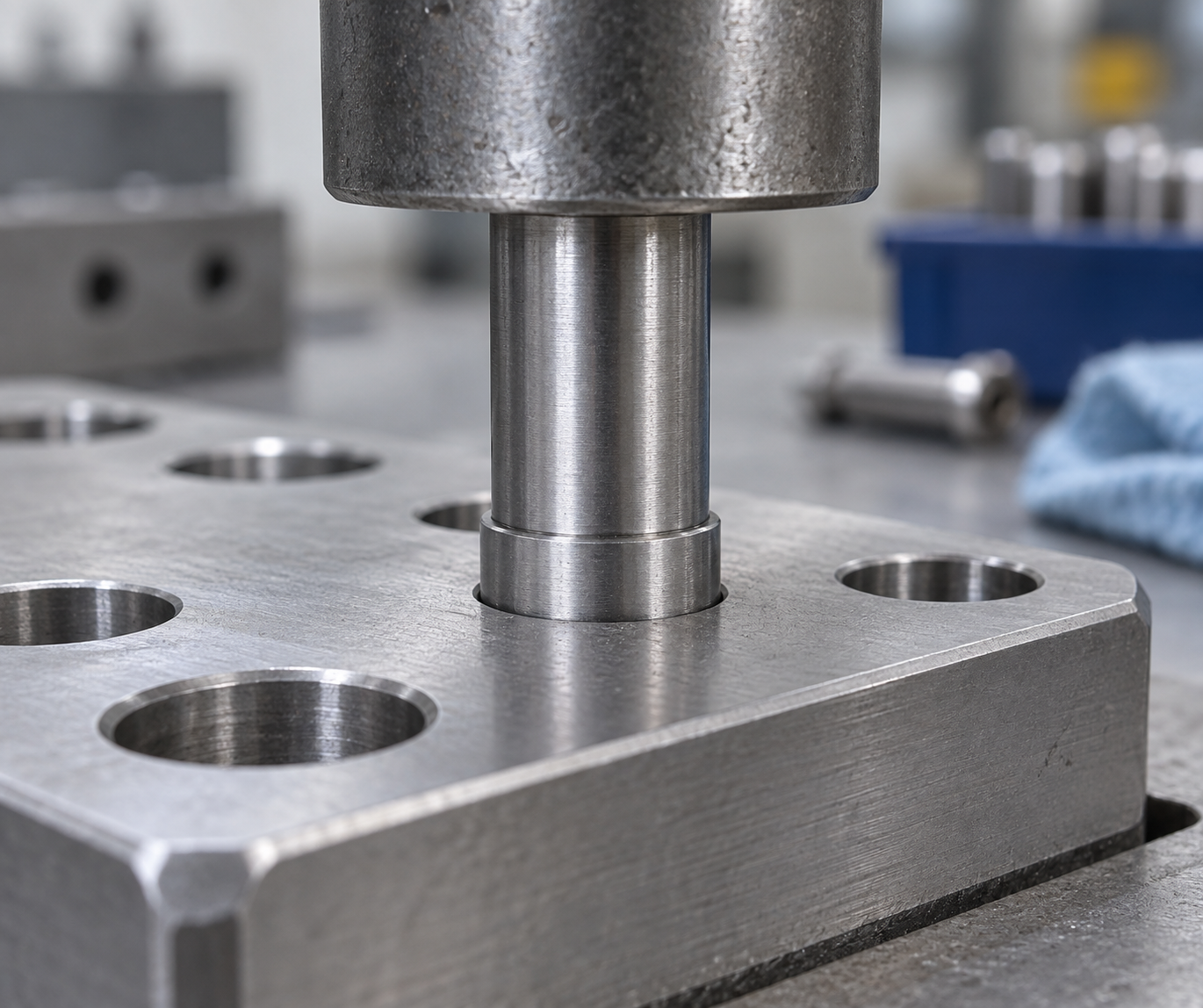
First distinguish standard parts from non-standard parts: the de facto standard is your drawing
The locating pin that causes an argument on the assembly floor is often not made wrong by the machine shop, but rather the drawing failed to state things clearly. Standard parts have ready-made specifications and ready-made prices; threaded parts and rolling bearings can be bought by model number. Non-standard parts have no unified classification, and no national standard to back you up—dimensions, tolerance bands, surface roughness, and datums all depend entirely on the customer drawing. So "non-standard" does not mean there is no standard; rather, the standard is carried by the drawing—if the drawing omits one line, a batch will scatter.
The judgment rule is simple: if the drawing only specifies basic dimensions and does not specify tolerance bands and datums, batch inconsistency is almost inevitable. Before quoting, confirm these three things with engineering—whether the mating surface tolerance band is written, whether the datum is unique, and whether roughness is specified as Ra. If you can't confirm them, don't discuss unit price yet.

Diagnosis 1: Missing tolerance and surface roughness definitions are the number one root cause of interference and offset
Checklist: go through these four items before quoting
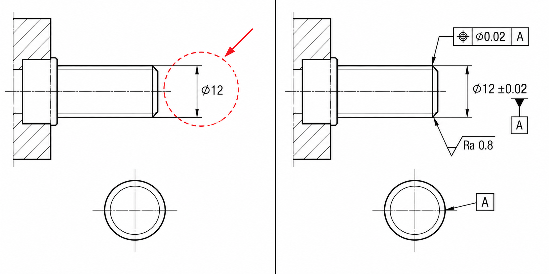
- Whether the mating surface specifies a tolerance band: interference fits such as H7/p6, clearance fits such as H7/g6; you cannot just write φ12.
- Whether the datum is unique: designate one primary datum for the locating surface and assembly surface, to avoid datum chain conflicts causing hole position offset.
- Whether roughness is specified as Ra: mating surfaces are usually Ra 1.6–0.8, non-mating surfaces can be relaxed to Ra 3.2; sealing surfaces are handled separately.
- Whether geometric tolerances are specified: coaxiality, perpendicularity, and position tolerance directly affect assembly; when missing, the supplier can only leave allowance based on experience.
if / then thresholds
Diagnosis 2: Where the post-processing chain breaks—the sequence of sandblasting, anodizing, and plating, and color differences
The same batch of aluminum alloy guide pins shows color differences after anodizing, and during assembly it is also found that the outer diameter has grown by 0.02 mm and won't fit into the hole. This is not a problem with anodizing itself; it's that post-processing was not written into the technical agreement.
| Symptom | Common root cause | Inspection action |
|---|---|---|
| Color differences and mottling in the same batch | Different substrate lots, inconsistent sandblasting grit, fluctuations in the anodizing bath | Require first-article color panel confirmation; specify the base material grade and blasting mesh size |
| Uneven film thickness, localized insulation | Anodized film thickness not specified, conductive oxidation and anodizing mixed up | Specify film thickness range on the drawing; clarify insulation requirements, choose one and do not mix |
| Assembly interference after oxidation | The film thickness consumed the fit clearance, and the drawing did not reserve allowance | When dimensioning mating dimensions, state whether the film layer is included, and reserve allowance if necessary |
The process chain order cannot be reversed: metal parts are generally sandblasted before painting, while plastic parts mostly use spray treatment; aluminum alloy color changes commonly use oxidation. Conductive oxidation film is thin and conductive, while anodized film is thick and has good insulation—choose the wrong one, and grounding or insulation will fail. Post-processing must clearly specify the process, sequence, and acceptance items in the technical agreement; otherwise, suppliers will follow their habits, and batches will not match. In addition to dimensions, the first article must also confirm the color panel and film thickness.
Inspection actions: three items for post-processing written into the drawing
- Specify the base material grade and condition, so it is clear whether color difference responsibility lies with the base material or the process;
- Mark the post-processing type, film thickness range, and whether it affects mating dimensions;
- Require first-article color panel and film thickness inspection report as the batch acceptance baseline.
Diagnosis three: supplier evaluation—is there DFM feedback before quotation?
The same drawing of a non-standard locating post sent to three suppliers: A replies only with unit price and lead time, B replies with unit price and two fillet suggestions, C replies with unit price, points out that the datum is not unique, suggests tightening the tolerance band to the mating surface, and asks about the post-processing sequence. The root causes of the first two symptoms are often hidden in this difference in response—replying only with unit price is equivalent to leaving drawing problems to be solved on the machine.
| Evaluation dimensions | Replies only with unit price | Provides DFM feedback before quotation |
|---|---|---|
| DFM upfront | Does not review the drawing, quotes directly from it | First proposes geometry simplification and machine matching suggestions |
| Tolerance/surface finish | Copies the drawing, does not ask about omissions | Marks undefined areas and confirms datums |
| Post-processing | Quotes only machining price, oxidation billed separately | Clarifies in-house or stable outsourcing and sequence |
| Difficult-to-machine materials | Quotes directly without asking grade | Confirms machinability and tooling plan |
| Quality control | Provides only finished product | Covers the full process from blank to finishing |
The core actions of DFM are just three: simplify geometry to match machine capabilities, balance material machinability with final performance, and precisely define tolerances and roughness by function. Suppliers willing to do these three things before quoting are usually also more willing to work with you on drawing changes during the first-article stage. If you need to first see machining capabilities covering milling, turning, and post-processing integration, refer to CNC machining capabilities.
Common questions
The following questions come from non-standard part quotation and acceptance sites. The answers are given in the order of “first check the drawing, then check the process chain, and finally check the supplier,” and can be used directly to align with engineering or procurement.
Non-standard parts have no national standard, so how do you judge whether what the processor makes is qualified?
The qualification criterion is not in the national standard, but in your drawing. If the drawing clearly specifies dimensional tolerance bands, datums, geometric tolerances, and surface roughness Ra, then gauges and inspection reports should be checked against these items. When the drawing only marks basic dimensions and does not specify tolerances and datums, batch inconsistency is almost inevitable—this is not the processor’s problem, but the lack of acceptance criteria. Before quoting, have engineering complete the key mating surfaces first, then discuss unit price.
The locating post assembly is too tight—is it machining out of tolerance or the drawing not defining the fit?
First measure three things: mating outer diameter, mating hole diameter, and coaxiality. If the dimensions are all within the drawing tolerances but it is still too tight, it is likely that the drawing only gave unilateral tolerances, did not give a fit tolerance band, or the datums are not unified. A common practice is to tighten mating surfaces and guide surfaces by function to the industry-common ±0.01 mm level, and relax non-mating surfaces; whether tighter tolerances are needed should be specifically evaluated according to assembly function. Do not tighten everything uniformly, as that only drives up cost.
Aluminum alloy parts have color difference and uneven film thickness after oxidation—how is responsibility divided?
First, confirm whether the technical agreement specifies post-processing. Aluminum alloys commonly use anodizing for color change, divided into conductive oxidation and anodizing; anodizing produces a thicker film with better insulation, and the two differ in appearance and dimensional impact. If the agreement doesn't clearly state the process type, film thickness range, and color plate, it's hard to assign responsibility for color differences. Check action: require first-article color plate and film thickness confirmation, and clarify whether post-processing changes mating dimensions—anodizing consumes dimensions, so mating surfaces need allowance reserved.
If a supplier only replies with unit price before quoting and gives no DFM feedback, can I place an order?
For simple parts, yes; for complex non-standard parts, the risk is high. The core of DFM is simplifying geometry to match machine capabilities, balancing material machinability, and precisely defining tolerances and surface finish. If the other party gives no feedback on sharp corners, deep cavities, thin walls, or difficult-to-machine materials (such as superalloys and engineering plastics like PEEK), it means no process review was done, and problems will only surface at first article. Decision rule: prioritize quotes that include DFM opinions or alternative solutions; for those with only numbers, ask follow-up questions before deciding.
Are non-standard parts always more expensive than standard parts? Where does the extra cost come from?
Generally higher than comparable standard parts, with the margin depending on material, tolerances, batch size, and post-processing complexity—there is no fixed multiple. The extra cost lies in one-off programming and fixturing, dedicated inspection gauges, outsourced post-processing, and scrap risk. To reduce cost, first simplify geometry and grade tolerances: apply precision only to surfaces that truly mate, and relax the rest; when the batch is large enough, then evaluate whether to switch to injection molding or replica molding, which must be confirmed based on drawings and quantities.
Key takeaways
- The de facto standard for non-standard parts is the customer drawing: critical mating dimensions must specify tolerance bands, datums, and surface roughness. If any one is missing, confirm with engineering before quoting—don't let the shop floor guess.
- When evaluating a supplier, first check whether they provide DFM feedback before quoting—those who only reply with a unit price and no process risks usually also have a weak post-processing chain and first-article confirmation.
- Tighten mating surfaces and guiding surfaces by function to the industry-common ±0.01 mm level; relax non-mating surfaces and cosmetic surfaces, and spend the saved cost on critical dimensions.
- Post-processing (sandblasting, anodizing, plating, silkscreen) must be written into the technical agreement and confirmed with a first-article color panel/film thickness, otherwise assembly interference and color differences will erupt en masse during mass production.
- For difficult-to-machine materials, looking only at performance and not machinability will cause cost and lead time to spiral out of control; confirm the blank state, tooling plan, and heat treatment sequence before deciding on the material.



