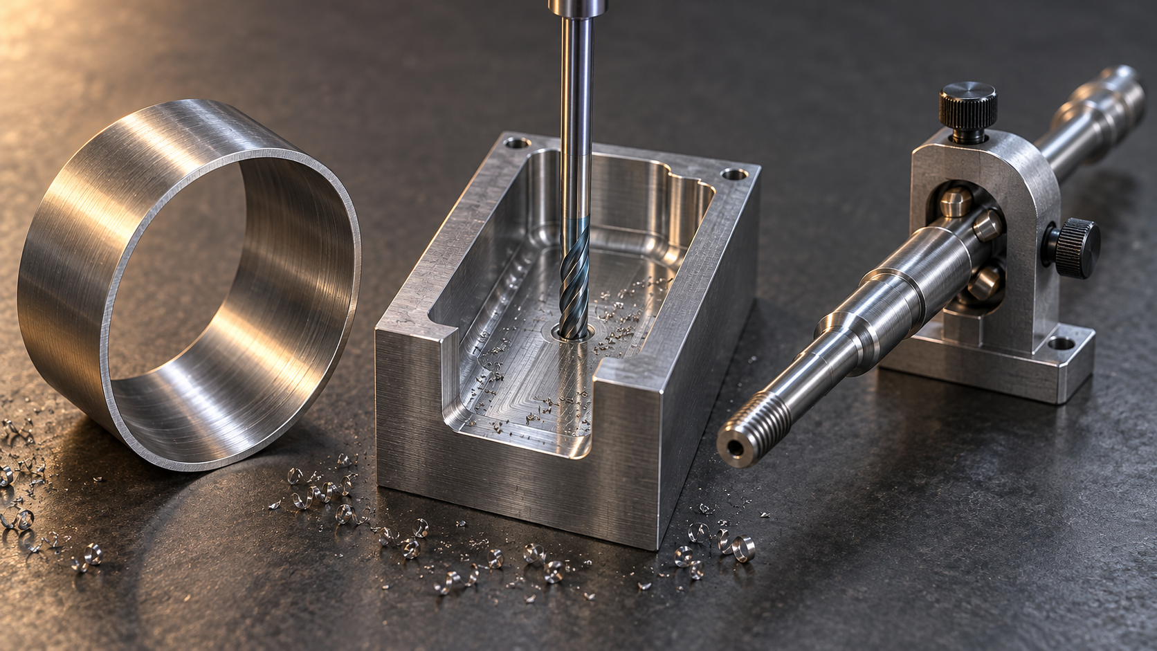
Don't rush to tighten tolerances: loss of control in these three part types is mostly not a precision problem
The drawing specifies ±0.02, the machine tool's precision is sufficient, yet the part still measures out of tolerance. The common reaction is to tighten tolerances, switch to higher-precision equipment, or even suspect the machine tool is out of calibration. But for thin-wall, deep-cavity, and long-shaft parts, loss of control often occurs after cutting begins, not in the machine tool's positioning accuracy.
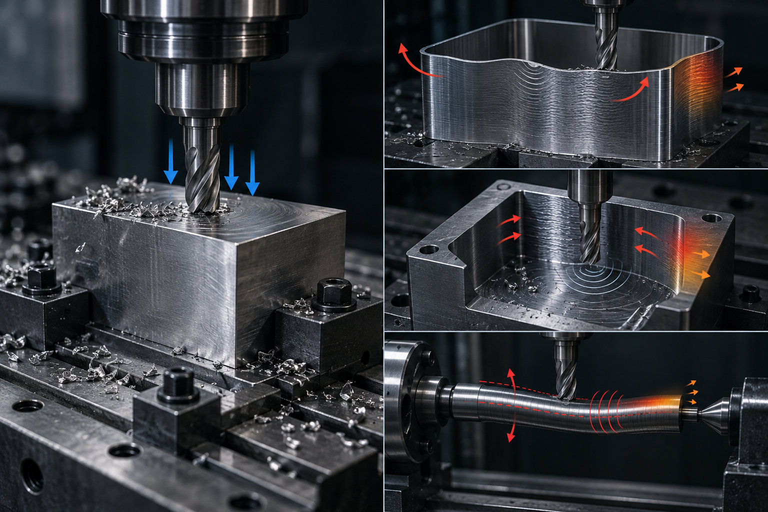
Misconception 1: The thinner the wall, the more material saved, so thinner is better
Halving the wall thickness does reduce material cost, but machining cost often doubles. This is the most common mismatch in thin-wall part quotations: the design side saves tens of grams of aluminum or plastic, while the manufacturing side loses an entire tier of cutting parameter margin.
What actually happens is another matter. The thinner the wall, the lower the part's rigidity, and the greater the proportion of deformation caused by cutting force, clamping force, and cutting heat. A common industry practice is: when wall thickness is increased from 1mm to 2mm, the usable feed and depth of cut can often be relaxed several times over, and roughing no longer needs "light cut, fast feed" to grind out time; conversely, when wall thickness is below about 1.5mm, most shops must actively reduce feed and depth of cut to prevent tool deflection and chatter marks, multiplying machining time. The rework rate for thin-wall parts is also generally higher than for conventional structural parts—industry sources often mention a level about 30%–40% higher, varying with structure and material.
Saving material is a design goal; being able to machine it is the delivery goal. Calculate these two separately, and the thin-wall account won't lose money.
Alternative criterion: look at the H/T ratio first, then the absolute wall thickness
There are two layers to the criterion that replaces "thinner is better." The first layer is absolute wall thickness: for metal parts, the commonly recommended value in the industry is about 0.8mm (absolute minimum about 0.5mm), and for plastic parts about 1.5mm (absolute minimum about 1mm); these are typical industry ranges, not standards, and not any factory's guaranteed value. The second layer is the height-to-thickness ratio H/T: when the ratio of free wall height to wall thickness is greater than 10, it is usually treated as a thin-wall part, and fixturing and toolpath strategy need to be reviewed in advance, rather than discovering at the quotation stage that it cannot be made stably.
What really should be confirmed on the drawing is three things: whether the wall thickness is below the above reference values, whether H/T exceeds 10, and whether the thin-wall area has reinforcing ribs or transition fillets. Writing these three items clearly on the drawing is far more useful than writing "please ensure no deformation" in the order notes. If the design truly requires a thinner wall, a common practice is to retain local thickened areas or process bosses and remove them after machining—the cost is an extra operation, but what is gained is dimensional controllability.
It should be noted that single-piece prototypes or trial parts usually tolerate thin walls better than production parts: once the fixturing scheme for a production part is fixed, the deformation and rework caused by thin walls are amplified onto every piece. So the same drawing that can be prototyped does not mean it can be produced stably in volume.
Misconception 2: Deep cavities can be machined as long as the tool is long enough
The most common argument in deep-cavity part quotations is: "This tool is long enough, why can't it cut all the way in one pass?" From a tool catalog, an end mill with 80mm overhang does exist; but each doubling of overhang reduces tool rigidity to roughly one-eighth of the original. Whether the tool can be mounted and whether it can cut stably are two different things.
What actually happens is: as overhang increases, radial cutting force bends the tool shank, the actual tool tip path deviates from the programmed path, and the side wall shows tool deflection and taper; at the same time, the tool's natural frequency drops, making it easy to couple with the spindle speed and produce chatter, leaving regular chatter marks on the surface. When the depth of cut is large and chip evacuation space is narrow, chips accumulate at the cavity bottom and are recut, and cutting force fluctuations further amplify deflection. Coolant can hardly reach the cutting zone, heat concentrates at the tool tip and the thin-wall root, and dimensions differ during machining and after cooling.
Deep-cavity accessibility checklist
- Internal fillet radius ≥ tool radius: otherwise the tool shank is forced to slow down or deflect at the corner, and chatter marks concentrate at the fillet. The larger the radius, the thicker the usable tool and the better the rigidity.
- Leave a chip evacuation channel at the cavity bottom: add a process hole to a closed cavity bottom or make the cavity bottom sloped so chips have an exit; otherwise you can only rely on high-pressure coolant and multiple retractions to evacuate chips.
- Write the layered strategy into the process: axial layering, radial stock allowance, and helical ramping are far more stable than "cutting all the way in one pass," at the cost of machining time.
- Switch to a split design when necessary: when cavity depth far exceeds 5 times the diameter and the batch is not large, splitting the deep cavity into two mating parts or switching to a 3D-printed/cast blank for finishing is often more controllable than forcing it through.
It should be noted that the above thresholds are common industry practices, not company commitments. At the same depth-to-diameter ratio, the stable zone differs greatly with material (aluminum alloy vs stainless steel vs titanium) and with tool coating and edge geometry. Only by providing cavity depth, fillets, bottom structure, and material together during drawing review can it be judged whether the strategy needs adjustment.
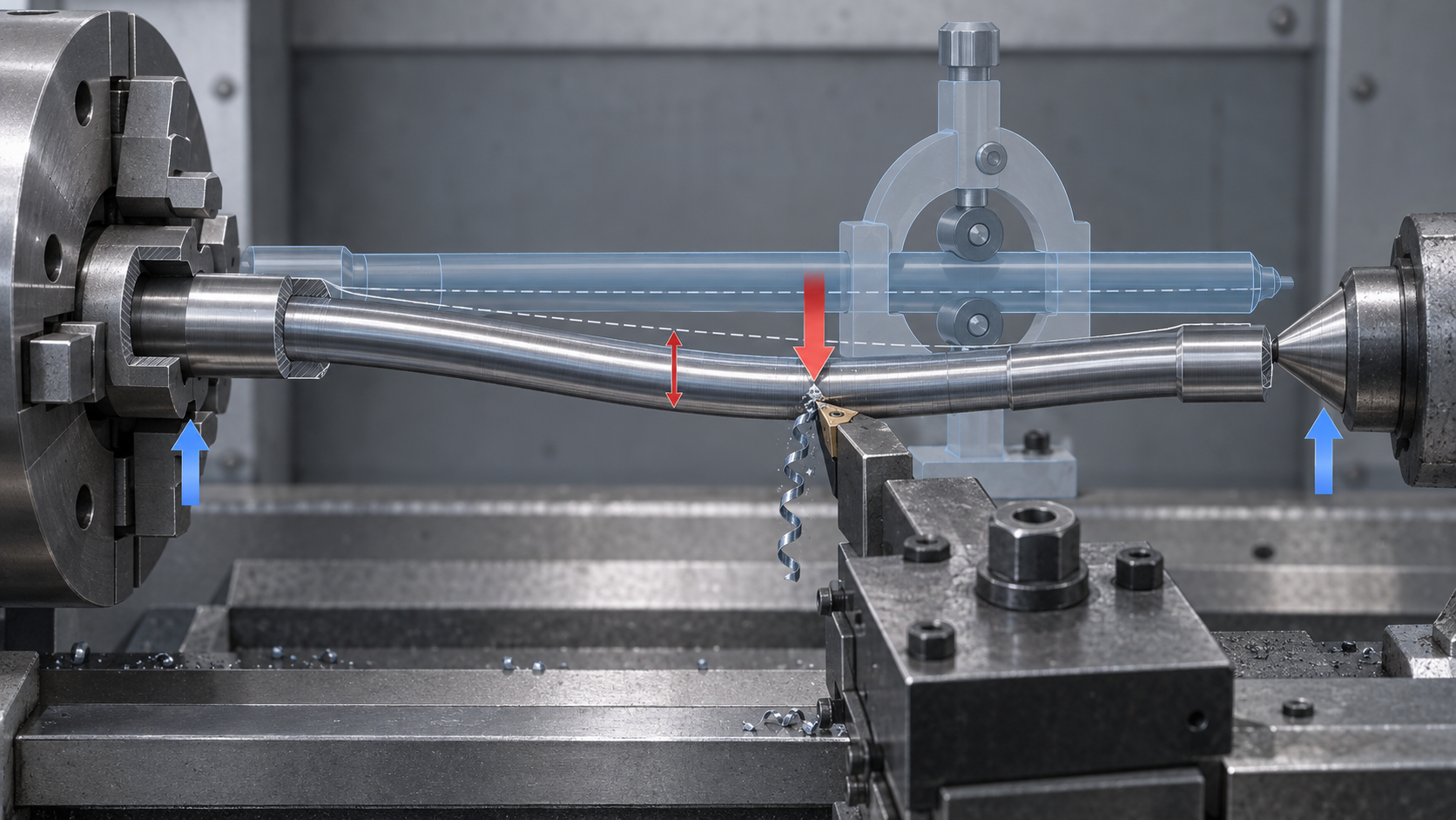
Misconception 3: A long shaft can be turned as long as both ends are supported
In lathe machining of long shafts, a very common default approach is: clamp one end of the blank in a three-jaw chuck, support the other end with the tailstock center, and then turn it down pass by pass. This approach is fine at small length-to-diameter ratios, but once the ratio goes up, problems appear. In the industry, shaft-type parts with a length-to-diameter ratio L/D over 8 are generally regarded as requiring additional support, but this is not an absolute standard; both the drawing and the actual blank condition must be confirmed.
Supporting both ends only constrains the two ends of the shaft; the middle section is still unsupported. When the cutting force presses radially against the workpiece, the shaft undergoes elastic bending like a simply supported beam, and the contour actually cut by the tool tip is larger than the theoretical value; once the pass is completed, the elastic recovery occurs, and the dimension shrinks back. The result is that the middle section has an oversized diameter and the two ends are undersized, forming a barrel shape. The more slender the workpiece, the more pronounced this tool deflection is. At the same time, cutting heat causes the shaft to elongate, and the axial constraint of the tailstock center converts the elongation into additional bending stress, so the dimension continuously drifts during machining. In terms of vibration, a slender shaft has a low first-order bending frequency and is very likely to couple with the spindle speed or the tool tooth passing frequency, producing regular chatter marks on the surface. These failure modes often occur simultaneously and amplify each other.
Alternative criteria: when support must be added
- Length-to-diameter ratio L/D within 8: two-end centers plus tailstock can usually cover it, but for finishing passes it is recommended to reduce the radial depth of cut and, if necessary, use a follow rest for pre-support.
- L/D between 8 and 15: consider a steady rest or follow rest, with the support point as close as possible to the cutting zone; the support point position should avoid discontinuous surfaces such as keyways and threads, otherwise the support will introduce new runout.
- L/D over 15: give priority to segmented machining, reversing and pick-up turning, or switching to cylindrical grinding, Swiss-type machining, or other processes more suitable for slender shafts; turning in one pass to the end is often not the optimal solution.
The support strategy also depends on the direction of the cutting force. If the three support jaws of a steady rest press against a reference surface that has already been turned on the workpiece, they can effectively limit radial displacement; if they press against the cast skin of the blank or the oxide scale of a forging, the contact stiffness is unstable and the effect will be reduced. For thermal elongation compensation, a common practice is to let the workpiece cool naturally or perform low-temperature stress relief after rough turning, and then finish turn; during finish turning, appropriately release the tailstock clamping force to give the shaft a slight amount of axial release space, reducing thermal stress bending. These are not guaranteed values, but commonly used engineering trade-off directions; specific parameters need to be adjusted according to the material, length-to-diameter ratio, and machine tool condition.
See it at a glance in one table: misconceptions, reality, and alternative criteria
Earlier we broke down the trigger points for thin walls, deep cavities, and long shafts respectively, but what is more common on the shop floor is this: the same misconception appears repeatedly across all three part types, only the failure manifestation changes its face. The table below places six high-frequency misconceptions side by side for easy row-by-row comparison during drawing review. The thresholds in the table are all typical industry ranges, used to judge the direction of risk, not AGX's machining commitments; specific values must be marked on the drawing and confirmed with engineering.
| The thinner the wall, the more material is saved, so the thinner the better | When wall thickness is below about 1.5 mm, the feed rate is forced down, and cutting force causes elastic tool deflection and chatter marks; slightly excessive clamping force produces ovality or edge collapse | For metal parts, recommended wall thickness ≥0.8 mm (absolute minimum about 0.5 mm); for plastic parts, recommended ≥1.5 mm (absolute minimum about 1 mm); H/T>10 is regarded as a thin wall and should be reviewed in advance | Whether this wall thickness bears load, whether reinforcing ribs are allowed, and whether the material removal sequence can be symmetrical |
| A deep cavity can be machined as long as the tool is long enough | As overhang increases, the tool deflects, chatters, and chips are not evacuated smoothly; coolant cannot reach the cutting zone, and the risk of tool breakage rises | Cavity depth controlled within 3–5 times the tool diameter gives better efficiency; over 5 times requires special tools or an adjusted strategy; cavity depth should preferably not exceed 5 times the largest dimension in the XY plane | Whether the internal fillet radius is ≥ the tool diameter, whether there is a chip evacuation channel at the bottom, and whether a split structure can be used |
| A long shaft can be turned as long as both ends are supported | When the length-to-diameter ratio is too large, tool deflection, cutting-force bending, and thermal elongation cause dimensional drift, and chatter worsens the surface | When the length-to-diameter ratio is >8, consider a steady rest/follow rest or segmented machining; keep the support point close to the cutting zone, and arrange roughing and finishing separately | Whether the blank allowance is uniform, and after which operation heat treatment and stress relief are arranged |
| It does not matter if there are several setups, since precision is guaranteed by the machine tool anyway | Each setup introduces new locating errors and clamping deformation, and the deviations accumulate beyond tolerance; the number of setups itself is a major cost item | Typical industry weights: number of setups accounts for about 25–35%, machining time 20–30%, material 15–25%. Prioritize reducing setup surfaces rather than changing the machine tool first | Whether process bosses can be used or key surfaces completed in one setup, and whether the datum is unified |
| Heat treatment is a later-stage matter; deal with it after machining | If the timing of stress relief is wrong, residual stress is released after finishing, and dimensions drift slowly, especially in thin-walled parts | Arrange stress relief after rough machining and before finish machining; leave uniform allowance on thin-walled parts before release | The heat treatment specification corresponding to the material grade, and whether intermediate stress relief is required |
| Just find any datum and measure it casually for inspection | If the inspection datum is inconsistent with the machining datum, the measured values may pass but assembly interference occurs; the deformation of unstable parts only becomes apparent in the free state | Align the inspection datum with the design datum; when necessary, use 3D scanning to confirm the free-state contour | The datum definition for critical dimensions, and whether free-state or clamped-state inspection is required |
The cost of losing control: setup, machining time, and rework
Many people treat loss of control over thin walls, deep cavities, and long shafts as a quality control issue: if dimensions are out of tolerance, rework; if rework is not possible, scrap.But it is first and foremost a quoting issue.For the same part, losing control versus not losing control differs not only in yield rate, but also in number of setups, machining time, and rework hours—these three items go directly into the unit price.
The typical industry cost weights are roughly: number of setups 25–35%, machining time 20–30%, material cost 15–25%, while the impact weight of feature complexity such as deep cavities, thin walls, and multi-face machining is about 4–7%. Note that these are not absolute proportions; different parts and different batch sizes will shift noticeably, but the ranking has reference value:fixturing and toolpath time are more expensive than material.
One more setup is not just one more tool setting
Thin-walled parts fear single-side clamping, long shaft parts fear being unsupported, and deep cavity parts fear losing the datum after flipping. To work around these problems, common practices are adding soft jaws, adding wrap-around clamping, adding process bosses, and increasing the number of flips—each one means a new locating error chain and new setup deformation risk. As the number of setups goes up, the quote naturally goes up, andone more setup means one more chance for datum drift.
Short case: why a thin-walled cylindrical part becomes more oval the more it is clamped
For a thin-walled cylindrical part, after turning the outer diameter, the inner bore was bored with a three-jaw chuck; after release, an oval was measured, and repeated tool adjustments did not help. The cause was not the tool, but the clamping force: the one-sided force of the three jaws pressed the thin wall into a triangle, and during cutting the dimensions were made correct in a “deformed state,” then sprang back into an oval after unclamping. Only after switching to wrap-around clamping, reducing clamping force, removing material symmetrically in layers, and leaving one finishing pass to run after unclamping did the dimensions stabilize. The cost of this type of problem is: extra soft-jaw tooling, extra operations, extra inspection time—all included in the unit price, not free rework.
| Cost item | Typical industry weight | How it changes when control is lost | Drawing/inquiry action |
|---|---|---|---|
| Number of setups | 25–35% | Adding soft jaws, wrap-around clamping, process bosses, and flips lengthens the locating chain | Mark clampable areas and datums, and specify allowed process bosses |
| Machining time | 20–30% | Thin walls reduce feed, deep cavities use small depth of cut, long shafts need more support, and toolpaths multiply | Mark critical dimensions and relax roughness on non-critical faces |
| Material cost | 15–25% | Allowance is left to prevent deformation, blanks are enlarged, and waste increases | Confirm blank form and allowance, and avoid unnecessary thickening |
| Feature complexity | 4–7% | Deep cavities, thin walls, and multi-face machining stack up, raising toolpath and inspection fixture costs | Assess whether it can be changed to a split design, changed fillets, or changed wall-thickness transitions |
| Rework/scrap | Varies with failure rate | Rework hours, re-setup, re-inspection, and even rematerializing | State before inquiry whether rework is allowed, or whether first-pass acceptance is required |
Ask a different question: instead of asking “how much is this part,” ask “what are the number of setups and key operations for this part.” The answer will tell you where the risk of losing control lies, and also where the padding in the quote is. When needed, the 3D model and critical dimensions can be sent to AI chat quote for a preliminary assessment, but whether the structure should be changed and whether the wall thickness should be increased still must be confirmed according to the drawing and engineering.
DFM countermeasure checklist: which places to change first on the drawing
The root cause of rework on parts that lose control is mostly not the machine tool, but that rigidity, fixturing, and material removal sequence were not clearly specified at the drawing stage. The order of changes matters:change the structure first, then the fixturing, and only last the cutting parameters. Doing it in reverse often leads to repeated trial cuts on the shop floor, costing far more than changing the drawing.
Structure first: wall-thickness transitions, fillets, and ribs
- Wall thickness transitions: Add a slope or step where thin and thick walls meet to avoid abrupt stiffness changes that create stress concentrations. Abrupt transitions are often where warping begins.
- Fillets: Make internal corner radii no smaller than the tool radius where possible, which both reduces corner-clearing passes and lowers the risk of cracking at sharp corners.
- Ribs: When you can't add thickness, use ribs instead of thickening. Rib height-to-wall-thickness ratios and rib spacing are common industry practices; specific values must be confirmed with engineering based on part function.
- Process bosses: Reserve removable bosses or clamping sections for fixturing, then cut them off after machining—this is more stable than clamping thin walls directly.
Fixturing comes next: datums and material removal sequence
Single-side clamping of thin-wall parts most easily produces ovality. A common approach is to switch to wrap-around clamping or vacuum fixturing so clamping force is distributed evenly around the circumference; for long shaft parts, add a steady rest or follow rest, placing support points near the location of maximum deformation. For material removal sequence, symmetric removal is more stable than single-side pocketing, with more balanced residual stress release. The timing of heat treatment or stress-relief operations must also be noted on the drawing—scheduling stress relief after roughing and before finishing is more cost-effective than straightening afterward.
Inspection datums and verification methods
The drawing must specify inspection datums; otherwise the shop and QC use different datums and the data won't match. For thin-wall and deep-cavity parts, 3D scanning for full-dimensional comparison is recommended—it detects ovality and warping trends better than caliper spot checks. Scan results can be used to work backward on whether fixturing or the removal sequence needs adjustment. Inspection datums and scan verification methods should be confirmed with engineering before quoting, to avoid discovering after production that a datum is unreachable.
When putting the checklist into practice, refer to the CNC machining capabilities and 3D scanning pages to confirm process boundaries; to evaluate cost changes after a drawing revision, use AI chat quoting for a quick comparison.
Frequently Asked Questions (FAQ)
The following questions are the ones most often raised during drawing review and before quoting. The answers give common industry criteria, not absolute standards; for your specific part, they still need to be clearly noted on the drawing and confirmed with the machinist.
How thin does a wall have to be to count as thin-wall?
In the industry, parts with wall thickness under 2mm, or a height-to-thickness ratio H/T greater than 10, are commonly classified as thin-wall parts. For metal parts, wall thickness is recommended to be no less than 0.8mm (absolute minimum about 0.5mm); for plastic parts, no less than 1.5mm (absolute minimum about 1mm). These are typical ranges, not hard standards; below the recommended values, fixturing methods and cutting parameters must be reviewed in advance.
How deep does a cavity have to be to count as deep?
The common criterion is the ratio of cavity depth to tool diameter. At 3–5 times the tool diameter, efficiency is good; beyond 5 times, tool deflection, chip evacuation, and cooling all worsen, requiring special tools or adjusted strategies. Another reference is that cavity depth should preferably not exceed 5 times its maximum XY planar dimension. Whether it can actually be machined depends on corner radii, bottom structure, and accessibility.
How should long shaft parts be supported to be stable?
When the length-to-diameter ratio exceeds 8, centers at both ends are often insufficient; a steady rest, follow rest, or segmented machining usually needs to be considered. Support point locations, cutting force direction, and thermal elongation compensation must all be specified in the process plan. The larger the length-to-diameter ratio, the higher the risk of tool deflection and chatter, and the harder it is to control surface quality and dimensional drift.
Can unstable parts be sorted out by inspection?
Partly, but not completely. CMM or 3D scanning can measure dimensional out-of-tolerance and ovality, but chatter marks, residual stress, and fixturing deformation often only appear after the clamps are released. Inspection should simulate the free state as much as possible, and datums and measurement conditions should be noted on the drawing. Sorting out rejects by 100% inspection usually costs more than solving the problem through fixturing and removal sequence.
What should be provided before quoting?
At minimum, a fully annotated 3D model and 2D drawing, specifying material, critical dimension tolerances, surface roughness, and datums. For thin-wall, deep-cavity, and long-shaft parts, the allowable fixturing locations and process bosses should also be stated. The more complete the information, the closer the quote is to reality; the more items missing, the higher the risk of later changes and rework.
Key takeaways
- Judge stiffness first, then talk tolerances: when H/T>10, depth-to-diameter ratio>5, and length-to-diameter ratio>8, evaluate "can it be fixtured stably" before tolerances; otherwise tolerances are just quotation friction.
- Don't try to "save" thin walls by reducing feed: increasing wall thickness from 1mm to 2mm often allows cutting parameters to be relaxed several times over; prioritize changing the structure, then the fixturing, and only lastly the parameters.
- Deep-cavity loss of control mostly happens in chip evacuation and toolholder overhang, not in the tool itself; marking accessibility on the drawing is more useful than marking tighter tolerances.
- The key to long shafts is not how deep a single pass goes, but the support point positions and thermal elongation compensation; length-to-diameter ratios with both ends supported and no support in the middle must be confirmed with process engineering in advance.
- Write the number of setups, machining time, and material utilization into the quotation assumptions; loss-of-control rework often comes from fixturing and heat, not from the material itself.



