Why can't the workshop start production when the drawing only says "3D printing"?
Last week, during a review of a bracket drawing, the material field said "3D printing, material unrestricted," the precision field was blank, and the post-processing field was blank. The same drawing was sent to three suppliers, with quotes ranging from 80 yuan to 800 yuan and lead times from 2 days to 10 days. Purchasing came with the three quotes and asked: which one is actually reasonable?
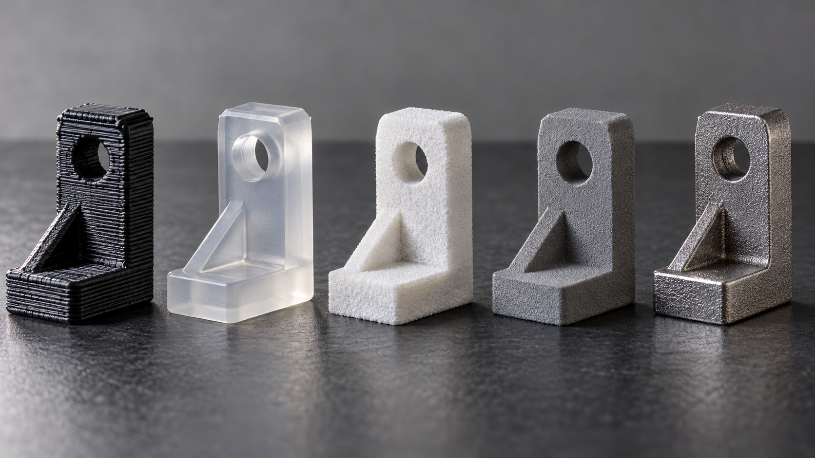
The problem is not that suppliers are quoting randomly, but that the drawing does not provide information that can be quoted. 3D printing is a process family, not a single process. FDM, SLA, SLS, MJF, and DMLS differ greatly in material, precision, anisotropy, and post-processing, so quotes and lead times naturally cannot converge.
Specifically, four items are missing: material family (determines the range of usable processes), precision requirements (determines layer thickness and equipment grade), batch size (determines whether tooling or duplication is worth it), and post-processing (determines surface quality and dimensional stability). If these four are not defined, suppliers can only guess in the most conservative or cheapest way, and the guessed result often does not match the design intent.
This article provides a decision sequence: first rule out unusable processes by material family, then look at the direction of applied force to determine whether anisotropy is fatal, then define precision and post-machining allowance, and finally calculate the cost inflection point by batch size. Each step provides criteria and common failure modes so you can directly compare them during drawing review.
Five mainstream 3D printing processes: comparison of materials, precision, and typical applications
The sentence the workshop fears most is "just 3D print this part." Printing is a process family, not a single process. FDM, SLA, SLS, MJF, and DMLS are completely different paths in material, precision, anisotropy, and post-processing. Choosing the wrong process may, at best, fail to meet surface roughness requirements, and at worst, crack under load after being installed on equipment. The table below first clarifies the boundaries of the five processes, then explains the criteria one by one.
| Process | Material range | Typical layer thickness | Common dimensional tolerance band | Degree of anisotropy | Typical applications |
|---|---|---|---|---|---|
| FDM | PLA, ABS, PETG, TPU, PC, nylon | 0.1–0.3 mm | ±0.3 mm or ±0.3% (whichever is greater) | High; Z-direction strength is often 50%–80% of XY direction | Large enclosures, jigs and fixtures, proof of concept |
| SLA | Photopolymer resin (standard, tough, heat-resistant, transparent) | 0.05–0.1 mm | ±0.1 mm | Medium-high; Z-direction strength is about 60%–90% of XY direction | Appearance verification, fine structures, transparent parts |
| SLS | Nylon PA12, PA11, TPU, glass-fiber-reinforced nylon | 0.08–0.15 mm | ±0.3 mm | Relatively low; Z-direction strength is about 80%–95% of XY direction | Complex structures, functional prototypes, low-volume end-use parts |
| MJF | Nylon PA12, PA11, TPU | 0.08–0.1 mm | ±0.3 mm | Relatively low, close to SLS | End-use parts with complex structures and high batch consistency requirements |
| DMLS | Stainless steel, aluminum alloy, titanium alloy, cobalt-chromium alloy, nickel-based alloy | 0.02–0.05 mm | ±0.1 mm | Medium to low, but heat treatment is required to eliminate residual stress | Metal functional parts, lightweight structures, conformal cooling molds |
The values in the table are common reference ranges in the industry, not guaranteed values from any single factory. Actual tolerances are affected by part geometry, print orientation, material batch, and post-processing. Before placing an order, you must confirm with the supplier according to the drawings.
FDM: Large size and cheap, but the Z direction is the weak point
FDM's advantages lie in size and cost. An industrial-grade FDM machine can print parts over 600 mm, material is priced by the gram, and printing a housing fixture may cost only a few dozen yuan. But interlayer bonding is a weakness: tensile strength in the Z direction is usually only 50%–80% of that in the XY direction. If the part must withstand tensile force or impact perpendicular to the print plane, FDM is not a good choice. In addition, FDM surfaces have layer lines, and appearance parts need sanding or post-processing.
SLA: Fine appearance, but limited heat resistance and durability
SLA uses a laser to cure resin, and layer thickness can reach 0.05 mm. Surface roughness Ra is commonly 1.6–3.2 μm, making it suitable for appearance verification and fine structures. However, the heat deflection temperature of standard resin is usually only 60–80°C, and it will soften if installed on heat-generating equipment. Heat-resistant resin can reach above 120°C, but its toughness and long-term stability are still inferior to nylon. For transparent parts, fine textures, and small-size high-detail parts, choose SLA.
SLS and MJF: No support required, suitable for complex structures
Both SLS and MJF are powder bed processes. During printing, the surrounding powder provides natural support, so no additional support structures are needed. This means cantilevers, internal channels, and nested structures can be printed, with no marks from support removal. SLS surfaces are relatively rough, feeling like fine sandpaper; MJF is finer than SLS on the surface and has better batch consistency, making it suitable for low-volume end-use parts of 20–200 pieces. Both use nylon-type materials, with toughness and chemical resistance superior to photosensitive resins.
DMLS: Metal functional parts, but post-processing cannot be skipped
DMLS uses a laser to melt metal powder, directly forming stainless steel, aluminum alloy, titanium alloy, and more. It is suitable for conformal cooling molds, lightweight brackets, and topology-optimized structures. But the as-printed state cannot be used directly: supports must be removed, heat treatment must eliminate residual stress, mating surfaces must be machined, and sometimes HIP densification is also required. These post-processing steps eat into lead time and cost. If the part only bears load at room temperature and does not have high precision requirements, DMLS may be less cost-effective than CNC.
The first cut in process selection: eliminate by material family, not by precision
The most common reason for rework on quotations is not insufficient precision, but the wrong material. I once saw a sensor housing where the drawing said “3D printing, ABS.” The engineer chose SLA photosensitive resin based on appearance precision. After the prototype was installed on the equipment and ran for two weeks, it softened. When removed and measured, all hole positions were off. The problem was not printing; it was that the material's heat resistance was only around 60°C, while the temperature inside the equipment compartment was above 80°C for long periods. Once the selection order is reversed—looking at precision first and material second—this type of failure is almost inevitable.
The correct order of elimination is: first cut out the processes that cannot be done according to material family, then compare precision, batch size, and post-processing among the remaining processes. Material family is a hard constraint, while precision is a soft constraint—if precision is insufficient, you can change machines, change layer thickness, or leave allowance for later machining. If the material cannot withstand the temperature or lacks mechanical properties, post-processing cannot save it.
Material family → available process mapping
| Material requirement | Processes that can be eliminated | Feasible processes | Key confirmation items |
|---|---|---|---|
| Metal mechanical properties / heat resistance >150°C | FDM, SLA, SLS, MJF | DMLS (metal laser melting) | Grade, heat treatment state, density, support removal plan |
| Transparent or high-gloss appearance | FDM, SLS, MJF (without post-processing) | SLA (transparent/high-gloss resin), MJF post-processing | Light transmittance, polishing process, yellowing resistance |
| Flexible / elastic | SLA rigid resin, DMLS | TPU-based FDM, SLS (some elastic powders) | Shore hardness, rebound rate, interlayer strength |
| Food contact / biocompatible | General-purpose FDM, general-purpose SLA resin | Processes requiring verification of specific material certifications | Material certification rather than process certification, confirm grade by grade |
| General structural parts / jigs and fixtures | — | FDM, SLS, and MJF all work | Load direction, batch size, surface requirements |
The way to use this table is to filter down from the first column, not to pick upward from the precision column. For example, if a part requires heat resistance above 150°C, you can directly rule out the four categories of plastic processes, and there is no need to agonize over whether FDM or SLA has higher precision—that step is already meaningless.
Four common misjudgments
- Treating "heat resistance" as "short-term heat resistance." The heat deflection temperature on a material datasheet is often a value under low-load conditions. After actual assembly, under preload and continuous heat, the softening point can arrive earlier. Leaving a 20–30°C margin is common practice.
- Treating "food contact" as a process attribute. There is no such thing as "SLS is food-grade." Only specific powder grades have passed the corresponding certifications. When the drawing does not specify a grade, you must confirm with engineering and cannot assume it.
- Using SLA resin for long-term load-bearing parts. After curing, photosensitive resin is highly brittle and has poor creep resistance, and may relax within a few weeks. For load-bearing parts, prioritize SLS/MJF or switch to machining.
- Needing metal but choosing "metal-like" resin. Electroplating and spray coating can only change appearance, not mechanical properties. If you need load bearing, conductivity, or high-temperature resistance, DMLS is the only path.
Only after the material family is determined does it make sense to compare the remaining processes by precision and batch size. The next step is to look at load direction—this is the failure point that distinguishes printed parts from machined parts and is most easily overlooked on drawings. If you need to first confirm material grades and process feasibility, you can check item by item by material family at the 3D printing quote entry, or refer to the grade descriptions in the materials library.
Anisotropy and load direction: the most easily overlooked failure mode of printed parts
Last year, a batch of FDM-printed sensor brackets made of ABS passed both shape and hole-position checks, but when tightened with M4 screws during assembly, two out of three cracked. The fracture surfaces were flat and separated along the interlayer interface. This was not a material defect; the load direction was exactly perpendicular to the print plane. The principal stress on the bracket came from screw preload, along the Z axis, while FDM interlayer bond strength is usually only 50%–80% of that in the XY direction (a common industry range; confirm with the material datasheet). The drawing did not specify print orientation, so the shop printed it in the orientation that minimized support, and the weakest strength direction happened to align with the load direction.
This is not an isolated case. Anisotropy is one of the most fundamental differences between printed parts and machined parts: machined parts (forgings, bar stock) have essentially isotropic mechanical properties, while printed parts are naturally weak along the build direction. If the principal stress direction is not aligned with the print direction during selection, all later discussion of precision and appearance is meaningless.
Degree of anisotropy by process: which are sensitive, which are not
| Process | Degree of anisotropy | Z-direction strength relative to XY direction (common industry range) | Reason for sensitivity |
|---|---|---|---|
| FDM | High | About 50%–80% | Interlayers rely on hot-melt bonding, and the interface is the weak plane |
| SLA/DLP | Medium-high | About 60%–90% | Differences in interlayer curing degree; post-curing can improve it |
| SLS | Low | Approx. 80%–95% | Interlayer fusion in powder sintering is relatively sufficient |
| MJF | Low | Approx. 80%–95% | Similar to SLS, with better batch consistency |
| DMLS | Medium | Approx. 70%–90% (depending on heat treatment) | Melt pool solidification is directional; after heat treatment it can approach isotropy |
The most important thing to note in the table is FDM: many people use FDM to print functional parts, but estimate strength based on injection-molded parts, and as a result, the part cracks as soon as it is tightened onto the equipment. SLA has less anisotropy than FDM, but the resin itself is brittle and is likewise prone to cracking along layer interfaces under impact loads. SLS and MJF have relatively low anisotropy and are suitable for structural parts with uncertain load directions or complex geometry, but the surface is rather rough, and mating surfaces still require post-machining. DMLS prints metal parts, and anisotropy can be improved through heat treatment, but heat treatment itself causes deformation, so allowance must be left.
Design rule: keep the principal stress parallel to the print plane
There is only one core criterion: the principal stress direction of the part should be as parallel as possible to the print plane (that is, perpendicular to the build direction). If this cannot be achieved, adjust in the following order:
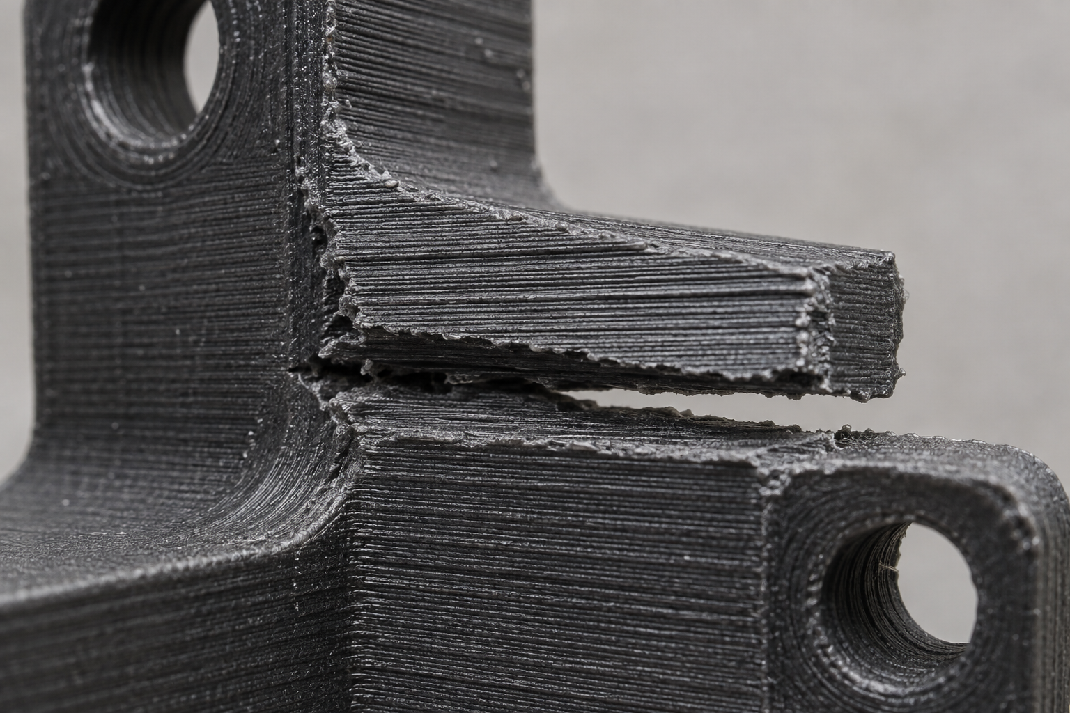
Final reminder: anisotropy data comes from material datasheets and actual measurements. Different machines, different layer thicknesses, and different infill rates will all affect the results. If the part involves safety or load bearing, do not rely only on empirical estimation. Ask the supplier for a Z-direction tensile test report for the same material, or directly perform sample verification.
Accuracy, fits, and post-machining: what printing can achieve, and what must be left with allowance
During assembly, you find that the shaft-hole fit is too loose, or the thread strips as soon as it is tightened—such problems are very common on printed parts. The root cause is often not that the printer is inadequate, but that the drawing specifies the printed part as if it were a machined part. The sources of dimensional error in printing are completely different from those in cutting: layer thickness determines Z-direction steps, material shrinkage and thermal deformation determine overall dimensional drift, and support removal leaves marks on the surface. Only by understanding these three points can you judge which features can be printed directly and which must be left with allowance for post-machining.
Typical tolerance ranges by process: first look at the order of magnitude, then discuss whether it is usable
Common industry reference values are as follows, but changing material or build orientation on the same machine may change the result by a factor of two. These numbers are only for judging whether a process is roughly sufficient; they cannot be used as acceptance criteria—specific tolerances must be confirmed with the supplier according to the drawing and material.
| Process | Common industry dimensional tolerance | Layer thickness range | Main sources of error |
|---|---|---|---|
| FDM | Approx. ±0.3 mm or ±0.3% (whichever is greater) | 0.1–0.3 mm | Layer steps, material shrinkage, nozzle path compensation |
| SLA/DLP | Approx. ±0.1 mm (small parts); for large parts, it scales with size | 0.05–0.1 mm | Resin shrinkage, post-curing deformation, support marks |
| SLS | Approx. ±0.3 mm or ±0.3% | 0.08–0.12 mm | Powder sintering shrinkage, uneven thermal field |
| MJF | Approximately ±0.3 mm or ±0.3% | 0.08 mm | Similar to SLS, with slightly better batch consistency |
| DMLS/SLM | Approximately ±0.1 mm (small parts), requires heat treatment for stabilization | 0.02–0.05 mm | Thermal stress, support removal, heat treatment distortion |
Mating surfaces, threads, bearing seats: do not print directly to final form
Directly printed mating surfaces can almost never meet fit requirements like H7/h6. The common approach is: leave 0.2–0.4 mm of allowance at positions requiring fits, then ream, tap, or CNC-finish after printing. The allowance depends on process precision—leave more for FDM, less for SLA/DMLS, but zero allowance for direct assembly is not recommended for any of them.
- Shaft-hole mating surfaces: Leave 0.2–0.4 mm allowance, then ream or bore after printing. For FDM parts, leave 0.4 mm; for SLA parts, 0.2 mm is acceptable.
- Threaded holes: Do not directly print internal threads. Leave pilot holes and tap after printing. Threads below M3 have a low success rate on printed parts; consider switching to heat-set brass inserts or self-tapping screws.
- Bearing seats: Post-machining is mandatory. The surface roughness and roundness of printed parts do not meet bearing press-fit requirements; leave allowance and then turn or grind.
- Sealing surfaces: O-ring grooves should be precision-finished after printing, or this feature should be CNC-machined instead. Print layer lines will cause seal failure.
- Locating pin holes: Leave allowance and then ream. When diameter tolerance must be controlled within ±0.02 mm, CNC is recommended rather than printing.
- Appearance surfaces: Can be printed directly to final form, but the surface treatment method (sanding, painting, vapor smoothing, etc.) must be agreed upon, and visual acceptance criteria must be specified.
A practical rule of thumb: if a feature requires precision turning, precision milling, or grinding to achieve on a machined part, it will likewise require post-machining on a printed part. The advantage of printing lies in rapidly forming complex geometries, not in replacing precision machining. Combining printing with post-machining is more economical than forcibly improving printing precision.
If a part contains both complex printed features and precision mating surfaces, consider a hybrid process: machine the whole part with CNC, or print a blank and then CNC-finish the critical surfaces. The specific trade-off needs to be judged based on part size, batch size, and cost. You can describe the features in the AI chat quote to get process recommendations.
Batch size and cost inflection point: when to switch processes
Last week, a client making industrial controllers came with the same enclosure drawing and asked: first run 30 units for trial production, possibly 3,000 units later—how should the process be planned? On the quote, 3D printing was 180 yuan per unit, injection molding was 12 yuan per unit but with a 48,000 yuan mold cost. Calculating it out, 30 units printed is 5,400 yuan, while injection molding with the mold amortized is 48,000 plus 360 yuan—the gap is obvious. But the real issue is not unit price, but that the cost structures differ: printing has no mold cost, and unit cost barely decreases with batch size; injection molding has a one-time mold cost, and unit cost is diluted as batch size increases. The inflection point is near the intersection of the two cost curves.
How to estimate the break-even point: a rough but usable calculation
Let the printing unit cost be Cp, the injection molding unit cost be Ci, the mold cost be M, and the batch size be N. Total printing cost = Cp × N; total injection molding cost = M + Ci × N. Setting them equal gives N* = M / (Cp − Ci). Substituting the above example: N* = 48000 / (180 − 12) ≈ 286 units. That is, below about 286 units, printing is more economical; above that number, injection molding starts to pay off. This calculation ignores printing volume discounts, injection mold life, and post-processing labor, but it is sufficient as a first cut. In actual quoting, substituting the supplier's tiered pricing will shift the inflection point toward 100–200 units.
A common industry rule of thumb is: for structural parts below 50–100 units, printing is usually cheaper than tooling; at 200–500 units, injection molding or vacuum casting starts to have an advantage; above 1000 units, injection molding is basically the only reasonable choice. But this is not an iron law—the larger the part and the more expensive the mold, the higher the inflection point; the smaller the part and the simpler the mold, the lower the inflection point. It must be calculated with actual quotes, not guessed.
The place of vacuum casting: the middle ground of 20–200 units
Vacuum casting (urethane casting) uses silicone molds for replication; the mold cost is far lower than steel molds, and the unit cost is between printing and injection molding. In the 20–200 unit range, it is often more economical than printing, and the surface quality and material options are closer to injection-molded parts—it can produce a feel similar to ABS, PC, and PP, and can also be color-matched. It is suitable for trial production, small-batch market launch, and trade show prototypes. The disadvantages are that silicone mold life is limited (usually dozens to hundreds of cycles), dimensional accuracy and batch consistency are inferior to steel mold injection molding, and complex undercut structures require part splitting.
| Batch size range | Recommended process | Rationale and risks | Notes |
|---|---|---|---|
| 1–20 units | 3D printing (FDM/SLA/SLS/MJF) | No mold cost, zero cost for design changes, short lead time | Anisotropy, surface texture, and material temperature resistance need confirmation |
| 20–200 units | Vacuum casting (urethane casting) or SLS/MJF | Vacuum casting surface and materials are closer to injection molding; printing is suitable for complex structures | Silicone mold life is limited; vacuum casting requires part splitting and draft angles |
| 200–1000 units | Injection molding (bridge tool/aluminum mold) or vacuum casting + CNC hybrid | Mold costs start to amortize; aluminum molds suit low-to-medium volumes | Aluminum molds typically last tens of thousands of cycles; steel molds suit long runs |
| >1000 pcs | Injection molding (steel mold) | Lowest cost per part, good consistency | High mold cost, high cost to change the design, requires design freeze |
If the part is a metal functional part, the logic is different: DMLS has no mold cost but is expensive per part, and by the time volumes reach a few hundred pieces, CNC machining or casting may be more cost-effective. The tipping point for metal printing usually comes earlier than for plastics, because metal printing has a high cost per part and post-processing (heat treatment, support removal, finishing) accounts for the bulk of it.
Recommended decision order: first confirm whether the part allows design changes. If the design is still iterating, even at volumes up to 300 pieces, first validate with printing or vacuum casting, and wait until the design is frozen before cutting a mold. If the design is frozen and the volume exceeds 200 pieces, go straight to getting injection molding quotes for comparison. Prototype vacuum casting suits the intermediate state of "design basically frozen but not yet wanting to cut a steel mold." When unsure, put the three quotes for 3D printing, vacuum casting, and injection molding together and calculate the total, and the tipping point will naturally emerge.
Inspection and acceptance: how to measure printed parts, how to judge them, and how to agree with suppliers
Disputes over acceptance of printed parts are 80% rooted in datums. Machined parts have clear clamping surfaces—place a CMM probe on one and the coordinate system is set. Printed parts don't—the bottom surface of FDM parts is support residue, the surface of SLS parts is a rough powder-sintered surface, and DMLS parts still carry the build plate. How do you expect an inspector to establish a datum? If the drawing doesn't specify it, the supplier establishes it by their own habit, while you measure according to assembly requirements, the two sets of data won't match, and a return slip follows.
Datum establishment: must be fixed on the drawing
A common practice is: designate a process datum surface on the drawing—usually the print platform contact surface, or a specially designed process boss. Before CMM measurement, first confirm whether this surface is complete on the printed part and whether it has been damaged by post-processing. If the platform surface has been sanded, the datum is lost. In that case, either re-agree to establish the datum using other features, or require the supplier at the quoting stage to retain a process boss and cut it off after acceptance.
For critical mating dimensions, in addition to tolerances, the drawing must also specify the measurement method. For example, for hole diameter, is a plug gauge or a CMM used? A plug gauge's go end passes and no-go end doesn't, making judgment simple; a CMM measures roundness, and the data looks good but assembly may still be an interference fit. When the two are inconsistent, assembly function prevails, not the measurement data.
Acceptance agreements for appearance parts and functional parts
| Part type | Acceptance item | Recommended agreement method | Common pitfalls |
|---|---|---|---|
| Appearance part | Surface roughness, layer lines, color difference | Provide a standard sample or visual limit sample, and agree on lighting conditions | Layer line direction is inconsistent between batches, and color difference is obvious after assembly |
| Functional part | Density, interlayer bonding strength | Agree on cross-section inspection or load testing, and CT if necessary | Only appearance passes inspection, but it cracks along the interlayer after installation |
| Mating part | Hole-shaft fit clearance | Agree on measurement positions and gauges, and leave machining allowance | Directly printed to shape, and after tolerance stacking it won't fit |
If a functional part involves safety or load, don't rely only on dimensional acceptance. A common industry practice is: take one piece from the same batch for a destructive cross-section to check for lack of fusion or porosity between layers; or perform a load test, loading to 1.5 times the design load, holding for a period, and checking for cracking. These tests must be written into the purchase order, otherwise the supplier by default only does dimensional sampling inspection.
Procurement-level agreements: five things to state clearly on the quote
The words "3D printing" cannot serve as a basis for acceptance. The quote and order must at least specify:
- Process: FDM, SLA, SLS, MJF, or DMLS—the acceptance standards for different processes are completely different.
- Material grade: Don't just write "resin" or "nylon"; specify the exact grade, such as PA12 or photosensitive resin 9000 series.
- Layer thickness: At 0.1mm and 0.2mm layer thickness, surface quality and Z-direction strength differ noticeably.
- Print orientation: The relationship between the principal stress direction and the interlayer direction must be marked on the drawing or order.
- Post-processing: Support removal, sanding, sandblasting, heat treatment, dyeing—each item affects the acceptance result.
If these five items aren't written, when acceptance comes the supplier says "that's just how 3D printing is," and it's hard for you to argue. If they're written clearly, both parties execute according to the same technical agreement, and disputes are at least halved.
If the part will later be assembled and mated, it's recommended to mark directly on the drawing: "Leave allowance on critical mating dimensions, and re-measure after machining." This way the supplier knows these aren't final dimensions, and you can keep the final precision control in your own hands before assembly. When you need a quote, state the process, material, layer thickness, print orientation, and post-processing clearly so the quote converges—AI chat quoting can help you fill in these parameters all at once, reducing back-and-forth confirmation.
Frequently asked questions (FAQ)
The following questions come up in almost every review. The answers give the basis for judgment, not guaranteed values; for specific tolerances, material grades, and post-processing requirements, the drawing and the supplier's written confirmation prevail.
How to choose between FDM and SLA?
Look at the application first, not the precision. For structural strength, large enclosures, and jigs and fixtures, choose FDM; for appearance verification, transparent parts, fine textures, and assembly demonstrations, choose SLA. Criteria: FDM's Z-direction strength is typically only 50%–80% of its XY-direction strength (common in the industry; confirm with the material data sheet), and load-bearing parts must be oriented correctly; SLA resin has limited heat resistance, and its long-term operating temperature generally should not exceed 60–80°C, so it will soften if installed on heat-generating equipment. For both, do not print mating surfaces directly; leave allowance and then finish them precisely.
Can printed parts be tapped directly?
It is not recommended to tap threads directly into printed holes. The thread profile strength of FDM and SLA is low, and the threads will strip after a few tightenings; SLS/MJF is somewhat better, but the wall density and dimensional consistency of the holes are still insufficient to withstand preload. Common practice: leave 0.2–0.4 mm allowance in the printed pilot hole, then tap it or press in a threaded insert (heat-set brass nut). For load-bearing threaded holes, prioritize inserts, or change to a through hole with a nut. If direct tapping is unavoidable, choose SLS/MJF, increase wall thickness, reduce tightening torque, and note this on the drawing.
Do DMLS parts need heat treatment?
In most cases, yes. The DMLS build process involves rapid melting and solidification and residual stress, and direct use may cause deformation or cracking. A common post-processing chain is: remove the build plate and supports → stress-relief annealing → (depending on material) solution treatment + aging or hot isostatic pressing → finish machining of mating surfaces. The specific schedule depends on the material grade (e.g., stainless steel, aluminum alloy, titanium alloy, and mold steel are all different), and it must be carried out according to material standards or the supplier's process documents; it cannot be generalized. For parts requiring mechanical properties, furnace test bars or same-batch testing should be agreed upon.
Can printing precision reach ±0.05 mm?
Overall part dimensional tolerances usually cannot. Common industry levels: FDM about ±0.3 mm or ±0.3% (whichever is greater), SLA about ±0.1 mm, SLS/MJF about ±0.3%, DMLS about ±0.1 mm (all need to be confirmed according to drawing, material, and build orientation). ±0.05 mm is generally achievable only on certain small features and after post-machining, and the measurement method and datum must be agreed upon. Do not expect critical mating dimensions to be formed directly by printing; leaving allowance and then precision-finishing by CNC is more reliable.
At what batch size should you switch from printing to injection molding?
There is no fixed number; it depends on part size, material, and mold complexity. A simplified judgment: 3D printing has no mold cost and high per-part cost; injection molding has mold cost and low per-part cost. The common industry crossover point is roughly 50–100 pieces, but it may be lower for small parts and higher for large or high-requirement parts. In the 20–200 piece range, prototype duplication (vacuum casting) is sometimes more cost-effective than printing, and the surface and material are also closer to injection-molded parts. Ultimately, base the decision on actual quotes and total cost comparison, not just per-part price.
Key takeaways
- Determine the material family first, then the process: metal parts directly rule out polymer processes, and plastic parts with temperature resistance >120°C should not use general-purpose SLA resin.
- The direction of applied force determines success or failure: the Z-direction strength of FDM and SLA is significantly lower than in the XY direction, so keep the principal stress direction away from layer interfaces as much as possible.
- Do not expect mating surfaces and threads to be formed directly by printing: leave 0.2–0.4 mm allowance and ensure them by reaming, tapping, or post-machining.
- When the batch size exceeds about 50–100 pieces, recalculate the total cost of injection molding or silicone casting duplication; the unit-price advantage of printing will disappear.
- Confirm the datum before acceptance: printed parts have no machined datum surface, so the fixturing and datum establishment method must be agreed upon before CMM measurement.



