An argument sparked by one drawing: should this part really go on a 5-axis machine?
Last week we reviewed a drawing for an aluminum alloy bracket: overall dimensions 180×140×90 mm, five of the six faces require machining, with two φ8H7 locating holes on the front face, one φ10H7 pin hole on the side face, and one IT7-grade guide rail slot on the bottom face. The drawing only specified the positional tolerance φ0.05 of each hole relative to datums A/B/C, without stating the machining plan. At the process meeting, two camps reached a deadlock—
- The 3-axis camp: It can be done in four setups, flipping with angle plates and locating pins, at a low unit price; but each flip re-establishes the datum, and the inter-face positional tolerance depends entirely on the fixture, which drifts once the fixture wears in volume production.
- The 5-axis camp: Complete five faces in one setup, the datum chain does not change, and positional tolerance is stable; but the machine hourly rate is high, the per-piece quote immediately rises, and sales frowns first.
This kind of argument comes up almost every week, and it actually has a determinable answer that does not rely on "feeling whether it is expensive." There are only four main lines of judgment: number of setups, tool accessibility, type of geometric tolerance, and batch size. If even one of the four crosses the line, 5-axis turns from "luxury" into "necessity"; if none of the four crosses the line, going 5-axis means spending more of the customer's money.
Below, these four are broken down one by one, each with criteria and counterexamples. First remember one premise: 5-axis is not a "more accurate machine tool," it is a "machine tool with fewer datum changes." Accuracy comes from not losing the datum, not from the number of axes itself—get this wrong, and every item below will be judged backward.
Criterion 1: Number of setups and datum chain—this is where the real value of 5-axis lies
When machining a polyhedron on a 3-axis machine, every change of face requires re-alignment and re-clamping. Each setup introduces a new set of locating errors and clamping deformation. After four faces, the datum chain passes from face A to face B and then to face C; when finally measuring the positional tolerance of face C relative to face A, the error is cumulative. A common situation on the shop floor is: individual face dimensions all pass, but the hole positions do not match during assembly.
The value of 5-axis is not "being able to machine complex surfaces," but completing multi-face features in one setup. The workpiece does not move; the spindle head or rotary table changes tool orientation, and all faces share the same datum. Inter-face relationships such as positional tolerance, perpendicularity, and coaxiality come directly from the machine's geometric accuracy, not from flipping the fixture to guarantee them.
How setup count translates into tolerance loss
| Comparison item | 3-axis + multiple setups | 5-axis one setup |
|---|---|---|
| Number of setups (4-face part) | 4 times, alignment per face | 1 time, workpiece fixed |
| Datum chain | A→B→C→D transmitted level by level, errors accumulate | Single datum, no transmission |
| Typical inter-face positional tolerance performance | Affected by fixture locating pin clearance and clamping deformation, large batch fluctuation | Depends on machine rotary accuracy, more stable repeatability |
| Perpendicularity/angled faces | Relies on angle plates or angle fixtures, angle error hard to control | Formed directly by the spindle head, angle guaranteed by the machine |
| First-article debugging time | Separate trial cut and alignment per face, time-consuming | One tool setting, orientation changed within the program |
Not all multi-face parts are worth going 5-axis. The criterion is: tight inter-face relationships (clear requirements for positional tolerance, perpendicularity, coaxiality) and number of faces to be machined ≥3. If there are only two faces, one flip on a 3-axis machine with a solid fixture is often cheaper. If there are many faces but no tolerance requirements between them—for example, only the outer contour, each independent—separate 3-axis machining can also pass.
There is another often overlooked point: whether the datum face itself needs machining. If the design datum is a raw casting surface, even one-setup 5-axis cannot save it—the deviation of the raw casting is directly carried into all faces. In this case, the datum face must be machined first before discussing one-setup machining. If the drawing only specifies hole position tolerances and not the datum face, confirm with engineering before quoting: is the datum face a cast surface or a machined surface.
Criterion Two: Tool Accessibility—Features You Can't Reach, Fixturing Can't Save
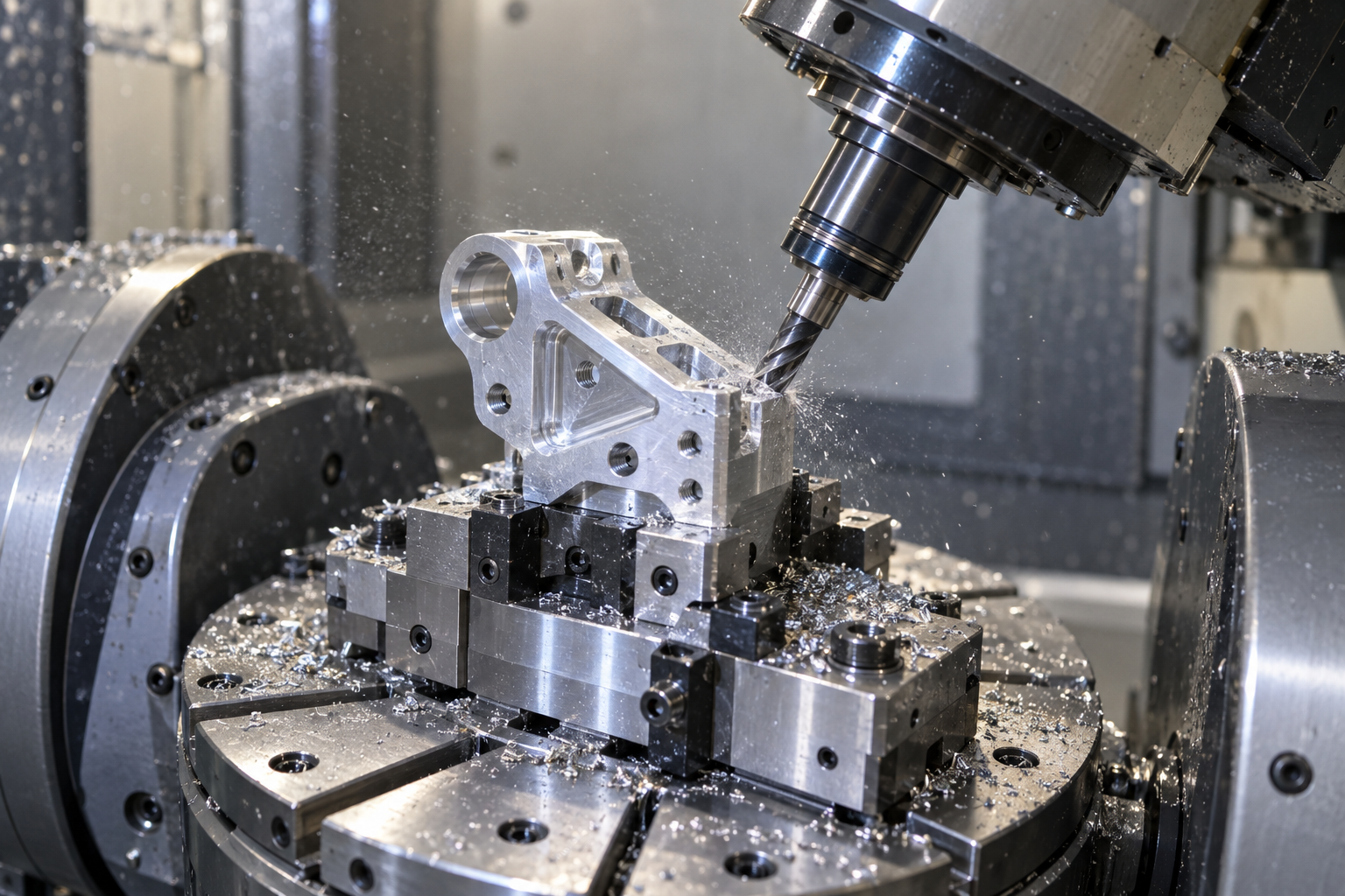
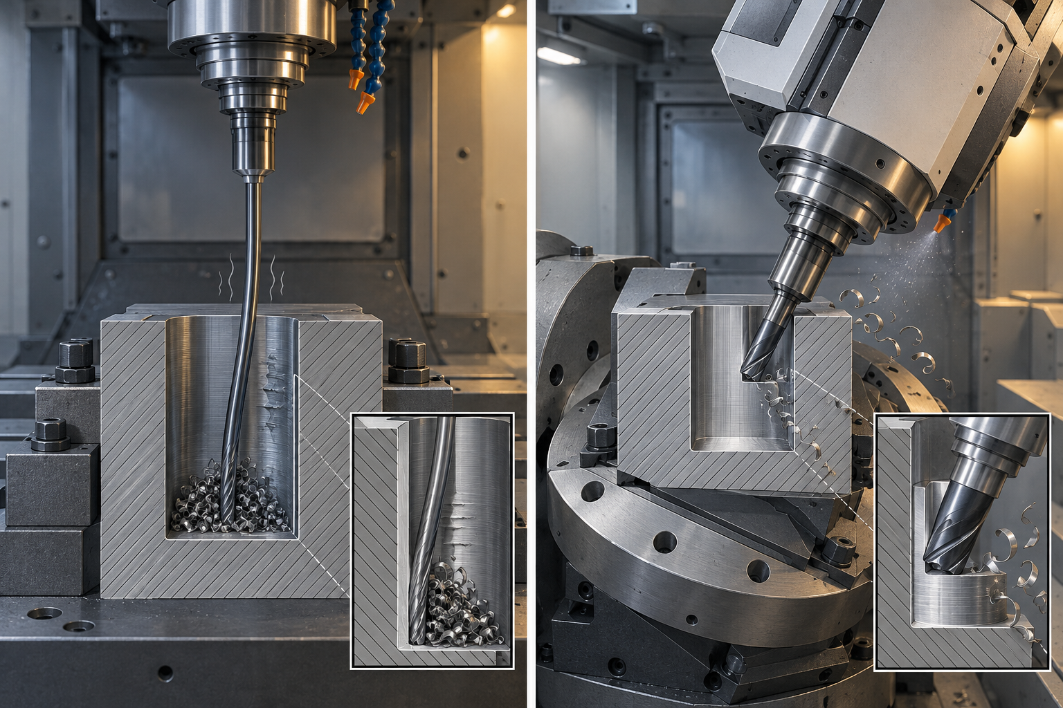
The number of setups determines the accumulated datum error, while accessibility determines whether the tool can cut that face in a rigid posture. These two things are often conflated: some people think that adding one more angled fixture will solve the machining of deep-cavity side walls, but the result is a tool with 80 mm overhang milling a 60 mm deep side slot, and the tool deflection is larger than the tolerance. Fixturing can change the part's posture, but it cannot change the tool's own rigidity.
Three Typical Accessibility Gaps
The first type is deep-cavity side walls: once the ratio of cavity depth to tool diameter exceeds 4:1, a 3-axis machine can only use an extended-length tool or a small-diameter tool—the former deflects, the latter breaks easily, and surface roughness often drops from Ra1.6 to Ra3.2 or worse. The second type is side holes and undercuts: the hole axis is at 90° to the spindle or at a negative angle, and a 3-axis machine must either use an angle head (poor rigidity, limited speed) or turn the part around for a second setup. The third type is compound-angle faces: a face has both pitch and yaw angles at the same time, and a 3-axis machine needs a dedicated angled fixture, with each angled face requiring separate alignment.
The value of five-axis is this: the tilting head or rotary table turns the part so that the tool axis always stays close to the feature normal, allowing the tool to be short and thick, with cutting force transmitted along the axis rather than bending the tool sideways. For the same side slot, a 3-axis machine uses a Ø6 extended tool with 70 mm overhang, while a 5-axis machine uses a Ø10 standard tool with 30 mm overhang—the chatter tendency and surface quality are not on the same order of magnitude. This is not a precision promise; it is the stability difference brought by a rigid posture.
Accessibility Self-Check List
- Cavity depth / minimum tool diameter > 4, and the side wall has roughness or perpendicularity requirements—high risk for 3-axis.
- There are holes or faces at an angle of 30°–150° to the spindle, and the number is ≥2—the angle head reverses direction repeatedly, losing on both efficiency and rigidity.
- There are features that a 3-axis machine cannot reach axially, such as undercuts, T-slots, and internal spherical surfaces.
- The angle between the normal of the face where the feature is located and the part's primary datum face exceeds 45°, and that face has a position tolerance requirement.
- For a single part, the tool overhang exceeds 5 times the toolholder diameter while still needing to guarantee Ra1.6 or better—suspect the 3-axis plan first.
Conversely, if all key features are accessible from one direction, or the side features are only through holes with no position or roughness requirements, then a 3-axis machine plus simple fixturing is enough. Don't go five-axis just to "look complex"—the five-axis rotary table's clamping itself consumes some rigidity, and thin-walled parts are actually more prone to deformation on a rotary table.
When actually quoting, writing "which faces cannot be reached, how many setups are needed, and whether the side holes have position tolerances" into the inquiry description is far more useful than just providing a 3D drawing. The accessibility judgment directly determines whether to use 3-axis, 5-axis, or turn-mill multitasking, and also determines whether the fixturing cost should be included.
Criterion Three: Geometric Tolerances and Surface Requirements—When Even Five-Axis Is Useless
When reviewing drawings, this kind of annotation is often seen: a flange, with face runout 0.02, outer diameter φ80 h6, inner hole roundness 0.008, surface Ra0.8. An engineer says, "One setup on a five-axis machine will make it stable"—this judgment is only half right. What five-axis solves is the inter-feature relationships brought by datum unification, not all tolerances.
What Five-Axis Can Help With: Position, Profile, Compound Angles
Position tolerance, profile tolerance, perpendicularity, and coaxiality—these datum-related geometric tolerances—are essentially about "how features line up with each other." With multiple setups on a 3-axis machine, each realignment introduces datum transfer error, and accumulation to 0.03–0.05 is very common; a single setup on a five-axis machine compresses the datum chain to the shortest, and this part of the error can be significantly reduced. For inclined faces and conical profiles with compound angles, a 3-axis machine either leaves tool marks from ball-nose point milling or uses an angle head to approximate in segments, making it very difficult to achieve profile tolerance within 0.02.
What Five-Axis Cannot Help With: Dimensional Tolerance, Roundness, Surface Roughness
Switching to another category of tolerances, the advantage of five-axis basically disappears:
| Tolerance Type | Main Determining Factor | Does Five-Axis Directly Benefit |
|---|---|---|
| Dimensional tolerance (e.g., φ80 h6) | Machine positioning accuracy, tool wear, thermal deformation | No, 3-axis can do it equally well |
| Roundness / Cylindricity | Spindle radial runout, tool rigidity, feed stability | No, and the geometric error of rotary table oscillation may even be introduced |
| Surface roughness Ra | Tool edge, cutting parameters, chatter | Indirectly; a good tilting-head posture can reduce tool deflection, but poor parameters still yield poor results |
| Face runout / Parallelism | Clamping face contact, datum unification | Yes, directly benefits from a single setup |
| Position tolerance / Profile tolerance | Datum chain length, accessibility | Yes, a core benefit item |
So when you see a requirement like "roundness 0.008, Ra0.8," don't rush to credit the five-axis. It depends more on the machine tool's own geometric accuracy, spindle condition, and finishing parameters. Conversely, if the drawing only has a bunch of dimensional tolerances and no inter-face geometric requirements, going five-axis is spending money for no return.
Counterexample: when five-axis is actually worse
A thin-walled part, wall thickness 1.5mm, requiring parallelism of 0.02 between the two sides. When clamped on a five-axis rotary table, if the clamping force direction is perpendicular to the thin wall, the centrifugal force during table rotation and the clamping deformation stack up, making the thin wall more prone to tool deflection than flat three-axis machining. The correct approach for such a part is to optimize fixturing and support first, rather than assuming five-axis is better. Similarly, for rotational parts requiring extremely high roundness, the symmetric force of turning is more stable than five-axis milling, and five-axis cannot replace turning.
Volume and cost: at what production range does five-axis pay off
The hourly rate of a five-axis machine is usually higher than a three-axis. A common industry practice is: for single pieces or small batches, complex structures, and parts with tight inter-face relationships, the tooling and rework time saved by single-setup five-axis machining can cover the price difference; but once volume ramps up, the math flips. The deciding point isn't "is five-axis good," but the fixturing and tooling cost amortized per piece. The table below breaks it down by production range.
| Production range | Five-axis machining | Three-axis + fixturing | Turn-mill compound | Special-purpose machine / transfer machine |
|---|---|---|---|---|
| Single piece / 1–50 pcs | Fewer setups, low tooling investment, often lower overall cost per piece; suitable for parts with many faces and poor accessibility | Requires multiple sets of tooling or multiple setups, high tooling amortization, datum chain errors accumulate | Suitable for parts mainly rotational with milling features on the end face | Not applicable; special-purpose machine startup cost cannot be amortized |
| Medium volume / 50–2000 pcs | Per-piece machining time is still high, but tooling maintenance is saved; if inter-face tolerances are tight, it may still pay off | After one-time tooling investment, per-piece cost drops significantly; suitable for parts with loose inter-face relationships | Highest efficiency for rotational parts, reduces setups | Becomes feasible, but changeover flexibility must be evaluated |
| High volume / 2000 pcs and above | The per-piece rate disadvantage is amplified; simple parts should move off five-axis | Tooling amortization becomes very low; suitable for parts with regular shapes and few faces | One of the top choices for high-volume rotational parts | Optimal efficiency and per-piece cost; suitable for parts with stable shapes and no long-term changes |
When five-axis still pays off at medium-to-high volume
If a part has multiple spatial angle faces, deep-cavity side features, and tight inter-face position requirements, even with fixturing, three-axis may fail to achieve acceptable yield due to datum conversion and multiple setups. In this case, five-axis at medium volume may actually be more economical than "three-axis + complex fixturing + rework." Conversely, if the part is just a few flat faces and through holes with loose inter-face relationships, high volume should use three-axis with dedicated fixturing or a special-purpose machine; forcing five-axis will only drive up per-piece cost.
Another variable is changeover frequency. In a high-mix, low-volume stage where the design is still iterating, the flexibility advantage of five-axis is obvious; once the drawing is frozen and volume ramps up, it's time to reassess whether to switch to a special-purpose machine or a three-axis fixturing line. There's no fixed number for this switch point; it usually depends on the actual difference in tooling investment, rework rate, and machine rate. It's advisable to put the per-piece costs of both routes side by side during the quoting stage.
A real trajectory: from three-axis rework to five-axis one-shot forming
Last year, a batch of aluminum alloy multi-face brackets required machining on all six faces, with a position tolerance of 0.05 between faces. The process engineer initially planned three-axis with two sets of angle-iron fixtures, four setups. When the first article was measured on a CMM, the position from datum A to datum B was 0.08—out of tolerance. During rework, the part was removed from the fixture, re-aligned, and re-milled, but the more it was reworked, the more it drifted—each setup stacked the datum error from the previous operation.
Later, it was switched to five-axis, completing all faces in one setup. For the same part, the position tolerance stabilized within 0.03. But switching to five-axis wasn't without cost: the part is a thin-walled frame structure with few clamping points on the rotary table, and vibration was pronounced during roughing; chatter marks appeared on the surface when the tool overhang was 4 times the diameter. In the end, it was controlled by adding auxiliary supports, reducing feed per tooth, and separating roughing from finishing. Chip evacuation also changed—after the five-axis tilts, chips tend to accumulate in dead corners of the cavity, so internal coolant and retract-and-clear chip-evacuation moves in the program are a must; otherwise secondary cutting scratches the machined surface.
The conclusion of this case is not "five-axis is always better," but rather: the value of five-axis holds only when inter-face relationships are tight, the number of faces is large, and three-axis setup count cannot be reduced. If only one face has a position requirement, three-axis with one set of fixturing is enough; going five-axis just raises the cost. After switching to five-axis, the three things to really watch are—whether clamping rigidity is sufficient, whether the chip evacuation path is clear, and whether tool length compensation is accurate. If any one of these three is not handled well, five-axis will still produce scrap.
What to specify clearly for inspection, quoting, and drawings
The most common failure with 5-axis parts isn't the machining—it's that the drawing datums and the inspection plan don't match. 3-axis parts usually use the bottom face as the primary datum, and inspection also aligns to the bottom face; 5-axis parts often machine multiple faces in one setup, and the design datum may be a side face or an axis. If the drawing still marks datums the 3-axis way, the setup error gets counted into the part error during inspection. A common practice is: clearly mark primary datum, secondary datum, and tertiary datum on the drawing, and note the inspection state (free state or clamped state). If it isn't noted, be sure to confirm with the designer.
Inspection: CMM, scanning, and first-article confirmation
For face-to-face position and profile of 5-axis parts, using a coordinate measuring machine (CMM) to probe points according to the datum system is the most direct approach; for complex surfaces or when comparing against a CAD model, using 3D scanning for full-field deviation color maps is more efficient. First-article confirmation should at least cover: flatness of the datum face, position between key faces, profile, and the feature with the worst tool accessibility. For batch parts, first article + sampling inspection is recommended, with sampling frequency determined by batch size and tolerance band width. The inspection report must include a datum diagram; otherwise, if the alignment method differs during re-measurement, the data cannot be compared.
Fixturing and accessibility information required for quoting
5-axis quotes vary widely, usually because incomplete information leads to different process plans. Before quoting, it is recommended to provide: blank form and allowance, clampable faces (which faces may be clamped and which must be machined), key tolerances and inspection requirements, batch size and delivery schedule, material grade and heat treatment condition. These directly determine whether dedicated tooling is needed, whether head/table simultaneous motion is required, and the tooling plan. When information is missing, the quoter can only estimate based on conservative processes, which is often too high or leads to later changes.
| Variable | Impact on quote | What should be clearly stated in drawings/inquiries |
|---|---|---|
| Number of setups | Each additional setup increases tooling and alignment time | Allowed clamping faces, datum faces |
| Tool accessibility | Deep cavities/side holes require special tools or head simultaneous motion, increasing programming and machining time | Feature depth, hole diameter, whether angle heads are allowed |
| Tolerance band | Tightening position/profile triggers more inspection and compensation | Key tolerance items and inspection methods |
| Batch size | Small batches spread tooling costs, resulting in higher unit price; medium-to-large batches can optimize cycle time | Annual usage or batch quantity |
| Material | Difficult-to-cut materials (such as titanium alloys and superalloys) increase tool wear and time | Grade, condition, whether heat treatment is required |
If the part truly requires 5-axis, organize the above information clearly before using AI chat quote or classic quote, which can reduce back-and-forth clarification. If you are still hesitating between 3-axis and 5-axis, you can first look at CNC machining capabilities to understand the boundaries of conventional milling, then decide whether to upgrade the process.
Frequently asked questions (FAQ)
The following questions are the ones most often asked during drawing review and inquiry. The answers are given in the order of "first look at the drawing, then look at the fixturing, and finally discuss cost," with no guarantees.
Are parts machined with 5-axis always more accurate than with 3-axis?
Not necessarily. The advantage of 5-axis is concentrated in "face-to-face relationships within one setup"—tolerances such as position, perpendicularity, and compound-angle profile that are transmitted through the datum chain. Single-part dimensional tolerances, roundness, and surface roughness depend more on machine rigidity, tooling, and cutting parameters; switching to 5-axis will not automatically improve them. If the drawing has a dimensional chain in only one direction, 3-axis with good fixturing often meets the requirement just as well, and is cheaper.
For small batches of a dozen or so parts, is 5-axis worth it?
It depends on the part itself. If there are ≥3 faces, tight face-to-face relationships, or side features that cannot be reached, the tooling and rework saved by 5-axis usually outweigh the hourly rate difference, so even a dozen parts can be worth it. Conversely, for simple single-face parts with loose tolerances, 5-axis only increases per-part machining time with no benefit. The order of judgment is: first count the number of setups, then calculate tooling cost, and finally compare unit price.
Can 5-axis replace turning?
For parts that are mainly rotational bodies with high coaxiality requirements, turning (or turn-mill multitasking) is still the first choice; 5-axis milling is inefficient on cylindrical surfaces and roundness is difficult to stabilize. Only composite parts such as "rotational body + multi-face side features" are worth considering for turn-mill multitasking or one-pass 5-axis forming. Putting pure shaft-type parts on 5-axis is mostly a waste of money.
With the same 5-axis capability, why do quotes from several companies differ so much?
Common variables include: fixturing plan (whether dedicated soft jaws/tooling are needed), blank allowance and material removal volume, tool length-to-diameter ratio and reduced speeds caused by poor accessibility, whether online measurement or full CMM inspection is required, and chip evacuation and cooling methods. Large quote differences are often not due to differences in machine hourly rates, but because the process plans are not aligned. When inquiring, clearly mark the clamping faces, accessibility, and key tolerances so that quotes are comparable.
What parts should not go on 5-axis?
There are typically four categories: single-face flat plates, pure rotational bodies, large-volume simple parts (which should use dedicated machines or injection molding), and parts whose tolerances are already loose and can be completed in one 3-axis setup. Putting these on 5-axis means paying extra for head/table motion time without gaining accuracy or schedule. During drawing review, rule out these four categories first, then discuss 5-axis.
Key takeaways
- Criterion 1: For parts with multi-face machining and tight positional/perpendicularity requirements between faces, reducing the number of setups with 5-axis is often more valuable than saving machining hours; putting a single-face flat plate on a 5-axis machine is basically a waste.
- Criterion 2: For deep cavities, side holes, and undercut features where the tool cannot reach and long overhangs or special angle heads are needed, prioritize 5-axis rather than forcing a 3-axis fixture.
- Criterion 3: For single-piece/small-batch, complex-shaped, and frequently modified parts, the benefit of one-setup 5-axis machining is greatest; high-volume simple rotational parts should go back to turning or special-purpose machines.
- Before quoting, write the datum, clamping faces, accessibility, and inspection method into the drawing or specification; otherwise the price advantage of 5-axis will be eaten up by second setups and rework.
- Five-axis can reduce setup errors, but it cannot replace reasonable tolerance callouts; loosening tolerances on non-functional faces saves more money than tightening everything.



