CNC Lathe Machining and CNC Machined Parts: First Clarify "Who Is Rotating"
Send the same 3D model to three suppliers, and the quotes may differ by several times. The problem is often not the price itself, but that the process type was never made clear: they quote for turning, you compare against milling, and naturally the numbers do not match. To discuss CNC lathes and CNC machined parts, you first need to establish a cognitive anchor—who is rotating.
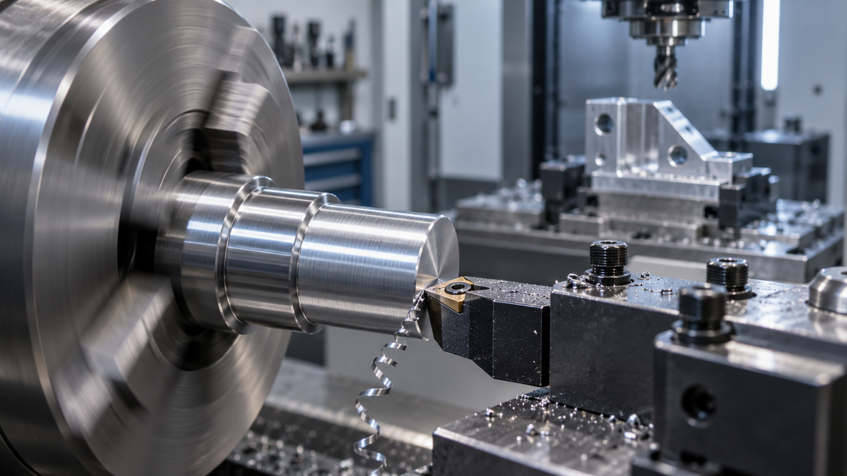
Turning: the workpiece rotates, and the tool is relatively stationary. Milling: the workpiece is stationary, and the tool rotates. This one difference directly determines which types of geometry are easy to machine and which are difficult. CNC machined parts is a broader category, and CNC turned parts is only one specific type within it, mainly for round, rotationally symmetric parts. Only after clarifying the scope does the later selection process become meaningful.
A Process Map: What Turning, Milling, Drilling, Boring, EDM, and Laser Each Handle
There is no need to memorize definitions; it is enough to connect them by "who rotates, who feeds." Turning relies on the workpiece rotating and is suitable for rotational contours; milling relies on the tool rotating and uses multi-axis interpolation to cover prismatic surfaces and complex curved surfaces; drilling and boring are usually additional operations to milling or turning, handling hole systems and internal circles; EDM and laser cutting take another path, removing material by electrical discharge or a high-energy beam, and are often used for geometry traditional tools cannot reach or for difficult-to-machine materials, usually slower than conventional cutting.
The way to use this map is: first check whether the main body of the part is rotationally symmetric. If so, prioritize turning as the main process; if the main body is a non-rotational structure such as a prism, housing, or bracket, move into the judgment of milling or turn-mill. As for the place of CNC lathe machining in threaded parts, the common industry situation is that for small and medium batches of threaded pipes and threaded fittings, turning, due to its flexibility and consistent precision, is often easier to adjust than specialized equipment. This point will be used repeatedly in the later selection process.
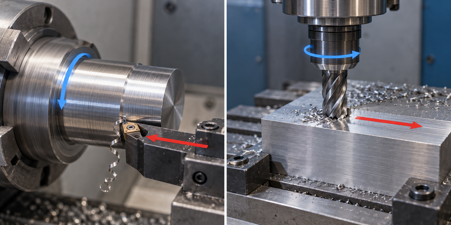
Using "who is rotating" as the first-layer filter can quickly eliminate the wrong process routes. The next step is to verify this initial judgment with the part geometry and to calculate the real trade-offs between turning and milling in terms of precision, efficiency, and cost.
CNC Turning vs CNC Milling: Core Differences and Suitable Part Geometries
First, here is an actionable judgment sentence: when the part is a rotationally symmetric body, prioritize turning; when the part has non-rotational features, move into milling or turn-mill. This sentence pulls process selection away from "habit" and back to geometry, and it is also the starting point for understanding the relationship between CNC lathe machining and the broader category of CNC machined parts. The fundamental difference between turning and milling lies in kinematics: turning is workpiece rotation with a relatively stationary tool; milling is a stationary workpiece with a rotating cutting tool. Who is rotating determines the types of geometry the machine tool can efficiently cover.
This distinction is not just a textbook concept; it lands directly on the parts list. Turning excels at shafts, pins, bushings, spacers, sleeves, rings, and threaded connectors—what these parts share is that their main body is defined by an axis of rotation, and by feeding the tool radially and axially, the outer diameter, end face, bore, threads, and grooves can be produced in a single setup. Milling excels at brackets, housings, molds, heat sinks, and mounting plates—these parts consist of planes, cavities, hole patterns, and curved surfaces, requiring the tool to remove material in multiple directions.
| Comparison item | CNC turning | CNC milling |
|---|---|---|
| Motion principle | The workpiece rotates, and the tool is fixed or only feeds | The workpiece is stationary, and the cutting tool rotates and performs multi-axis motion |
| Best-suited geometry | Rotationally symmetric bodies: shafts, pins, bushings, sleeves, rings, threaded parts | Prismatic bodies and complex 3D contours: brackets, housings, molds, heat sinks |
| Typical precision tendency | Concentricity and diameter dimensions are usually easier to control; suitable for batch threads and cylindrical surfaces | High precision for complex dimensions and curved contours; hole positions and flatness depend on fixturing and accessibility |
| Efficiency characteristics | Continuous cutting of a single rotational contour, smooth chip evacuation, suitable for small to medium batches | Requires tool changes, contouring, and corner cleaning; efficiency decreases as the number of features increases |
| Cost drivers | Aspect ratio, chatter on slender parts, thread and groove complexity, material machinability | Tool accessibility, internal corner radii, number of setups, thin-wall vibration, 3-axis or 5-axis |
So how do you choose? Sketch the part on graph paper: if its shape remains essentially unchanged when rotated about an axis, start by evaluating the turning option—cost can usually be estimated fairly accurately from the bar stock diameter, length-to-diameter ratio, and thread specifications. If the part has holes, cavities, or flat surfaces that can only be reached from multiple directions, turning will leave a large number of "unmachinable" areas, and that's when you evaluate milling or turn-mill multitasking. Notably, in small-to-medium-batch production of threaded parts (such as threaded tubes and coupling sleeves), turning is often the primary machining method due to its flexibility and consistent precision—threading is a natural strength of turning, whereas cutting threads on a mill typically requires additional operations.
Why "part geometry" determines the process earlier than "material"
For the same part, aluminum and steel have different cutting parameters, but geometry determines whether it can go on a lathe and whether a five-axis machine is needed. Material affects tool selection, spindle speed and feed, and whether heat treatment is required, while geometry affects the machine type, the number of setups, and whether EDM corner clearing is needed. When requesting a quote, stating the geometry criteria clearly will help the supplier provide a comparable proposal more effectively than saying "I need aluminum parts machined" first. In other words, for CNC machined parts, quote differences at the first level often come from different process types, not from price competition within the same process.
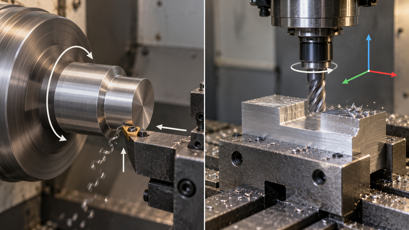
Use this comparison table in actual communication: in the inquiry email to the supplier, write a sentence like "The main body of this part is a body of revolution, expected to be turned; please confirm whether turn-mill multitasking is recommended." The other party can then directly judge whether to quote a multitasking process, rather than quoting a higher price based on default three-axis milling. The next step will expand the geometry criteria into the choice among three-axis, five-axis, and turn-mill multitasking, and explain where the cost focus of each option lies.
Choosing a process from part geometry: bodies of revolution, prismatic parts, and turn-mill multitasking
One sentence is enough to judge: rotational symmetry favors turning first; only when non-rotational features appear do you move to milling or turn-mill multitasking. Part geometry is the primary criterion; material, tolerance, and batch size all come after it. With the same drawing, first check whether it is a shape produced by rotation about a central axis—if yes, a CNC lathe is the default entry point; if not, go further down the line.
Put common parts into this framework: shafts, pins, bushings, spacers, sleeves, rings, and threaded connectors have bodies of revolution as their main body. Even with a wrench flat, an end-face threaded hole, or a cross oil hole added, they still start from a CNC lathe, and a small number of eccentric features can be completed with a live tool turret or a second setup. Prismatic parts such as brackets, housings, molds, and heat sinks have main bodies enclosed by flat and angled surfaces, cannot be formed by turning, and go directly to three-axis or five-axis milling.
Three-axis, five-axis, and turn-mill multitasking: choose by geometric complexity
After prismatic parts enter milling, they must be further divided into another category: whether all machinable surfaces can be directly accessed from above. If yes, three-axis is sufficient; only when there are deep cavities, undercuts, angled holes, or multiple faces need to be covered in a single setup do five-axis or turn-mill multitasking come into play.
| Process type | Ideal complexity | Main advantages | Main cost drivers | Core value |
|---|---|---|---|---|
| Three-axis milling | Prismatic parts whose faces can all be directly accessed from above | Simple programming and fixturing, versatile tooling | Number of setups, secondary machining operations | Low cost per unit time for simple geometry |
| Five-axis milling | Deep cavities, undercuts, complex surfaces, multi-face features | Covers multiple angles in one setup, expanding the tool's reachable area | Machine hourly rate, programming complexity | Reduces setups and secondary machining, total cost may be lower |
| Turn-mill multitasking | Rotational body + prismatic/eccentric/transverse features | Turning and milling integrated in one machine, reducing the number of setups | Equipment hourly rate, process planning difficulty | Complex parts with rotational + prismatic features completed in one go |
One takeaway line after the table: If the geometry can be completed in a single setup, don't split it into two operations. The cost of splitting operations isn't just machining time—it also includes the alignment error of the second setup and the cost of fixturing. It's common in the industry for five-axis and turn-mill multitasking equipment to have a higher hourly cost than three-axis or pure turning equipment, but if it eliminates two or three setups and one secondary machining operation, the total cost is often actually lower—this must be calculated for the specific part, and can't be generalized.
When turn-mill multitasking is worth it
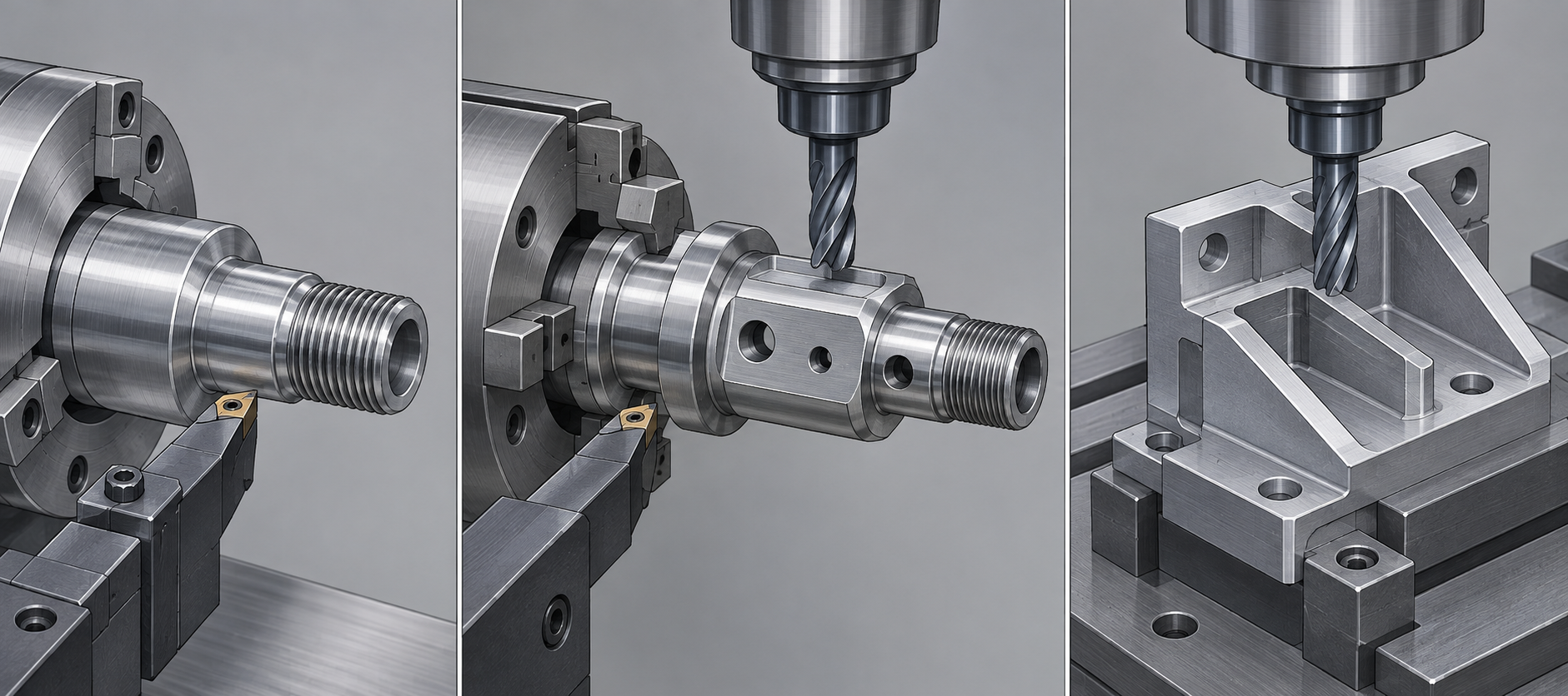
The value of turn-mill multitasking appears when a "rotational main body + non-rotational features" exist at the same time. Typical examples include drive shafts with transverse milled flats and radial holes, connectors with face cams, and hydraulic fittings with multiple angled oil passages. If such parts are split into turning plus milling, the coaxiality between the two setups must be ensured by fixtures and alignment, and accumulated error is hard to control; once integrated into one machine, the datum is transferred within a single setup, eliminating the tool-setting and re-inspection steps.
Conversely, purely rotational parts don't need turn-mill multitasking—the extra equipment hourly rate buys no benefit. The same goes for purely prismatic parts; five-axis is enough. The selection order can be fixed: first determine rotational symmetry, then determine whether there are non-rotational features, and finally check whether these features can be reached from the existing setup direction. Once these three steps are done, the process type is basically determined.
Typical types and design limitations of CNC turned parts
The previous sections have been discussing whether to choose turning or milling. This section takes a different angle: assuming the process has already been decided as turning, which details on the drawing will make the tool unable to move, make the part vibrate, and double the cost. There is only one core point—in turning, the tool is fixed and the workpiece rotates; all geometric constraints grow out of this premise.
Internal and external corners: cylindrical tools cannot clear sharp corners
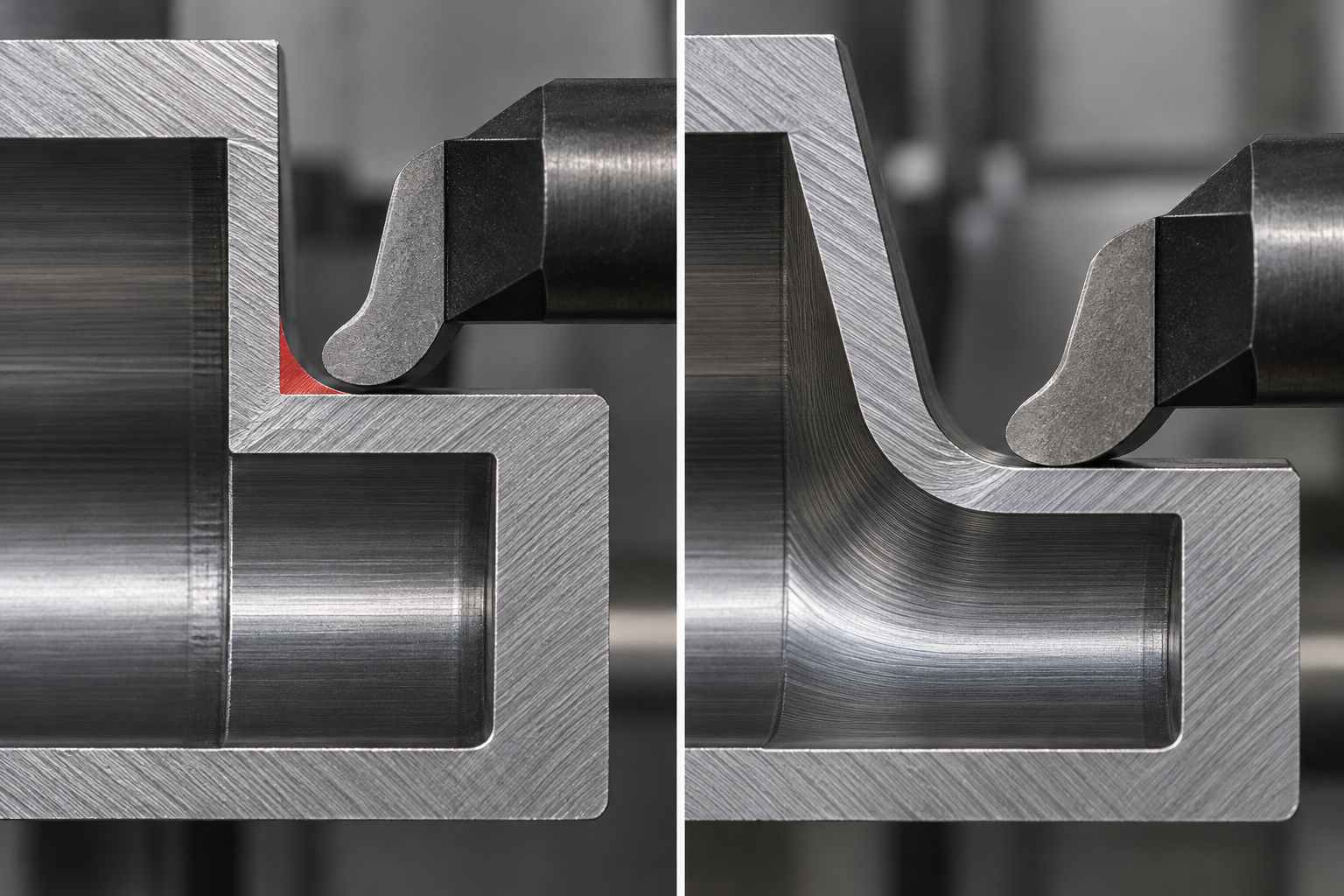
If the internal corners of a CNC turned part are drawn as sharp right angles, no matter how small the tool nose radius is, they cannot be cleaned out completely. The supplier can only add an EDM step or switch to a smaller tool to clear the corner, and both the process and the quote will go up. Avoid sharp internal corners, because cylindrical tools cannot clear corners. Adding a radius at the corner (commonly R0.4–R1.6 mm in the industry, depending on the drawing), or slightly angling the steep side wall, often allows a single lathe tool to complete the contour in one pass.
The same applies to external corners. Many parts have a chamfer around the outer edge, and here is a detail that is easy to overlook: the chamfer size should preferably be slightly larger than the end mill radius. A common industry approach is that when the end mill radius is 0.125 in (3.175 mm), the chamfer is about 0.130 in (3.3 mm), so the tool can cut in cleanly without leaving a step. When confirming, use the actual tool radius as the basis, and it is recommended to note this on the drawing or ask the supplier directly.
Slender parts: uneven rotation, chatter as soon as the tool touches
Slender shafts and slender pins are among the most problematic types of CNC turned parts. Avoid slender turned parts, because the workpiece lacks rigidity when rotating and is prone to uneven rotation and chatter with the tool. The larger the length-to-diameter ratio, the more obvious the tendency for cutting forces to bend the workpiece, resulting in taper, chatter marks, and dimensional drift. In design, shorten the overhang whenever possible; when a slender shape is truly needed, it is usually necessary to add a steady rest or follower rest on the process side for intermediate support, or machine in segments and then join them. For this type of part, it is best to state the length-to-diameter ratio clearly before quoting.
Thin walls: vibration or even fracture under cutting forces
For thin-walled rotational parts such as sleeves and rings, once the wall thickness drops to a certain level, cutting forces cause elastic deformation of the wall surface, leading to out-of-tolerance dimensions in mild cases or direct cracking in severe cases. The way to judge this is quite simple: when the wall thickness is too thin relative to the diameter, both clamping force and cutting force can easily deform the part. Consider leaving process bosses, adding temporary support, or dividing the work into roughing and finishing passes so that stress has a chance to release. Exactly how thin counts as thin depends on the material, diameter, and clamping method. It is recommended to mark functional and non-functional surfaces separately so the supplier can decide where material can be sacrificed.
Tool accessibility: three-axis machines can only reach from above
Accessibility is not a problem unique to turning, but once side holes, cross slots, or non-rotational features appear on a CNC machined part, it immediately becomes apparent. Three-axis equipment can only machine features that are directly accessible from above, and structures on the side or bottom must either be flipped for a second setup or handled on a five-axis machine. Flipping introduces new alignment errors, and as the number of setups increases, the datum drifts. So during drawing review, ask this question: can one tool reach this feature from the current direction? If not, should the design be changed, or should the cost of complex machining be accepted?
Looking at the points above together, the design limitations of CNC turned parts all point to the same word—rigidity: tool rigidity, workpiece rigidity, and fixturing rigidity. Adding radii at corners reduces the load on the tool, shortening overhangs and adding support reduces the load on the workpiece, and reducing flips reduces the load on the datum. Think these three things through on the drawing, and both the yield and the quote for turned parts will be more controllable.
Common materials for CNC machined parts and a quick comparison
Aluminum, stainless steel, steel, and titanium: a quick comparison of metal materials
| Category | Material | Main advantages | Common uses |
|---|---|---|---|
| Aluminum alloy | 6061, 7075, 2024, etc. | Lightweight, good machinability, usually can be machined at higher speeds; many surface treatment options | Brackets, housings, heat sinks, fixtures, drone structural parts |
| Stainless steel | 304, 316, 17-4PH, etc. | Balances corrosion resistance and strength; 316 is more common in chemical and medical environments | Shafts, pins, bushings, threaded connectors, food and medical equipment parts |
| Carbon steel and alloy steel | 1045, 4140, 42CrMo, etc. | High strength, wear-resistant; mechanical properties can be adjusted after heat treatment | Shafts, gear blanks, connectors, heavy-duty structural parts |
| Titanium and titanium alloys | TC4 (Ti-6Al-4V), etc. | High strength-to-weight ratio, corrosion-resistant; commonly used for biocompatibility applications | Aerospace structural parts, non-load-bearing parts related to medical implants, high-end sports equipment |
| Copper alloys | Brass, bronze, beryllium copper, etc. | Good electrical and thermal conductivity, wear-resistant; brass usually has very good machinability | Electrical contacts, bearings, valve bodies, connectors |
Engineering plastics: an alternative option when metal is too heavy, conductive, or too expensive
| Category | Material | Main advantages | Common uses |
|---|---|---|---|
| Engineering plastics | POM (acetal) | Good rigidity, low friction coefficient, dimensional stability, and machinability close to that of brass | Gears, bushings, guide rails, precision sliders |
| Engineering plastics | Nylon (PA6/PA66) | Good toughness, wear resistance, and impact resistance; dimensions change after moisture absorption | Rollers, wear pads, snap fits, light-load structural parts |
| Engineering plastics | PTFE (Teflon) | Extremely strong chemical resistance and very low friction coefficient; strength and rigidity are relatively low | Seals, insulating parts, corrosion-resistant liners |
| Engineering plastics | PEEK | High temperature resistance, chemical resistance, and higher strength among plastics; price is usually significantly higher than POM | Aviation interior parts, medical devices, semiconductor peripheral parts |
Process factors and input checklist that affect CNC machining quotes
Send the same 3D model to three suppliers, and the quotes that come back may differ by several times. Many buyers' first reaction is, "Is the second one just quoting randomly?" In fact, the more common root cause is that the three suppliers assigned the part to different processes—one quoted it as CNC turning, one as 3-axis milling, and another as 5-axis or mill-turn. Machine hourly rates, programming effort, and the number of setups are all different, so the prices are naturally not on the same scale. To make quotes comparable, first align the process type and input conditions.
Turning, 3-axis, 5-axis, mill-turn: where the pricing differences lie
These four process types have different cost structures. Turning and 3-axis milling use relatively mature equipment and programming, so unit prices are usually lower; 5-axis machines and mill-turn equipment often have higher hourly costs, but they reduce the number of setups and secondary operations, so for batches or complex parts the total price may actually be lower. So when you see a high price, don't rush to negotiate it down—first ask: What process do you plan to use for this part?
- Turning (CNC lathe): The workpiece rotates, suitable for bodies of revolution. Programming is simple and single-piece efficiency is high, but only rotationally symmetric features can be made.
- 3-axis milling: The tool moves along X/Y/Z from above, suitable for prismatic parts and flat machining. The number of setups may be the main cost item.
- 5-axis milling: The tool can approach the part from multiple angles, reducing setups and enabling complex curved surfaces, but equipment and programming costs are higher.
- Mill-turn: Turning + milling are completed in one machine, minimizing setups, suitable for complex parts with both rotational and non-rotational features.
Six inputs that make CNC machined part quotes comparable
If you only provide a 3D model, the supplier can only guess the tolerances, guess the material, guess the surface requirements, and guess what the part is used for. The guessed processes will differ, and the quotes will not be comparable. To make quotes horizontally comparable, at least state these six items clearly at once:
- Part drawing (2D): Mark datums, critical dimensions, and tolerances/GD&T. Datums determine the fixturing plan and directly affect the quote.
- 3D model: STEP or IGES format, to avoid the supplier rebuilding the model themselves.
- Material specification: Grade, condition (such as T6, annealed), and whether there is room for substitute materials.
- Quantity and batch: One-off, small batch, or mass production? Different quantities may lead to completely different process choices.
- Surface finish and special treatments: Ra requirements, anodizing, plating, blackening, heat treatment, etc.
- Application context: Where the part is installed, what loads it bears, and whether it has mating surfaces. This determines which tolerances are critical tolerances.
The easiest thing to overlook is the application context. For the same part, if it is only a cosmetic part, the tolerances can be relaxed; if it is a mating surface, tighter tolerances and better surface roughness may be required. Tighter tolerances usually lead to higher manufacturing costs—because they require more precise machine tools, slower feeds, and more inspection. This is also why giving only the model without stating the use can cause quotes to differ by several times.
Two easily overlooked cost factors
One is electrical discharge machining. It is usually slower than traditional cutting, but it can handle hard materials or special geometries such as sharp internal corners. If the part design has internal corners that cannot be cleared, the supplier may be forced to add an EDM operation, and the quote will rise noticeably. The second is secondary machining. If a turned part also has milling features (such as side holes or flats), it must either be moved to a turn-mill machine or require an additional setup and alignment. The time cost of the latter is often underestimated.
When requesting a quote, you can include “please state the intended process” in the email. This way, even if three suppliers quote differently, you can see whether the difference comes from process selection or from efficiency differences under the same process. When you need a quote based on drawings, you can upload drawings and models at the CNC quote portal, or first check the CNC machining capabilities to confirm the process scope. AGX does not promise fixed lead times or prices—the specific terms are subject to actual drawing review.
Typical CNC lathe and milling machining process: from drawing to inspection
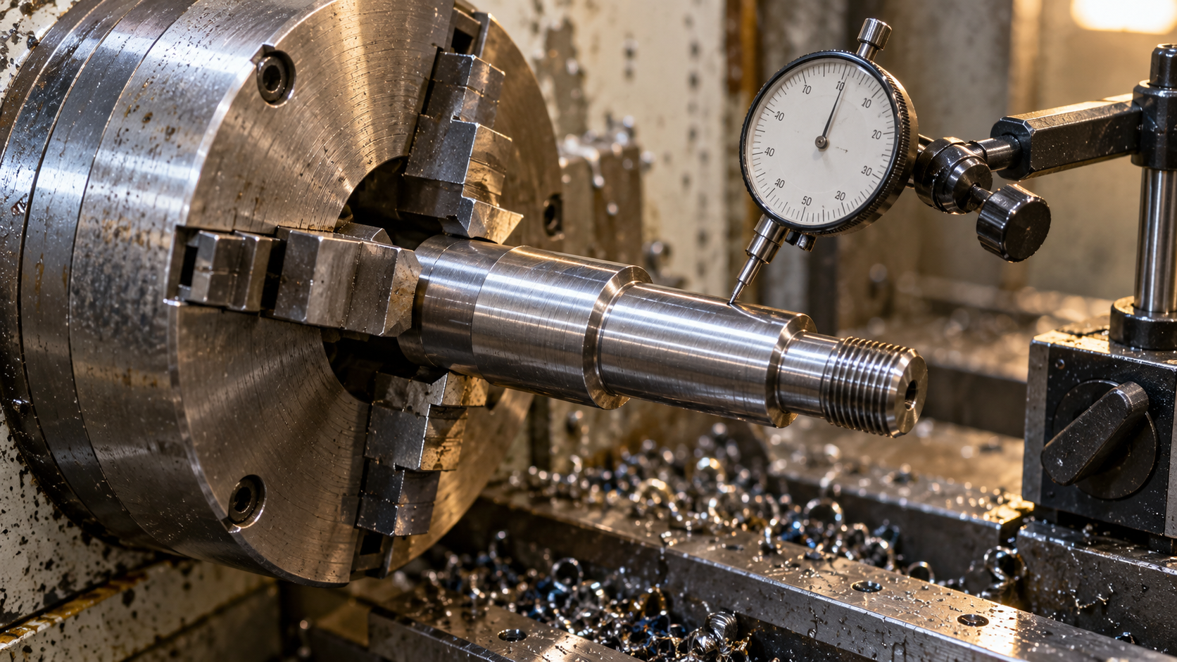
Once the quote is discussed and the process is decided, the part must actually go onto the machine. CNC lathe machining and CNC milling machining differ in their emphasis on fixturing, alignment, and cutting parameters, but the process skeleton is similar. Below is a walkthrough in typical order, with only key actions at each step, not expanded into a tutorial.
The fundamental difference between turning and milling in fixturing comes from kinematics: turning involves workpiece rotation, so the fixture must ensure rotational accuracy and dynamic balance; milling involves tool rotation, so the fixture only needs to hold the workpiece securely and ensure a reliable locating datum. This also explains why reducing the number of setups is usually the core value of turn-mill machining—each fewer setup means one less alignment error and accumulated tolerance, which is especially obvious for shaft-type parts with high concentricity requirements.
Putting the choice onto the drawing: an input checklist for suppliers
At this point, the logic for choosing a process is already clear: CNC lathe machining corresponds to rotationally symmetric parts, prismatic bodies or complex curved surfaces among CNC machined parts are handed to milling, and only when rotational features and prismatic features appear together does turn-mill machining come into play. But choosing the right process does not mean the quote is usable. Sending the same 3D model to three suppliers and getting quotes that differ by twice the price is often not because someone is quoting randomly, but because each has assumed a different process type, a different fixturing plan, and a different understanding of tolerances. To get comparable quotes, the inputs must first be comparable.
Confirm the process type, then compare prices
When requesting a quote, include “do you plan to use turning, 3-axis milling, 5-axis, or turn-mill for this part?” Different processes differ greatly in machine hourly cost, programming complexity, and number of setups. Putting turned parts and 5-axis milled parts in the same price comparison table makes the numbers meaningless. After the supplier replies with the process type, ask the quote to specify how many setups are included and whether secondary machining and surface treatment are included—these are the real places where prices diverge.
Drawings and models: giving critical tolerances something to rely on
A 3D model (STEP or IGES) defines shape, while a drawing defines requirements; the two cannot replace each other. If only the model is provided, the supplier can only estimate based on default tolerances and default surface roughness, so quotes naturally diverge. The drawing should at least mark: datum planes and datum axes, dimensional tolerances and geometric tolerances for mating surfaces (GD&T, such as runout, concentricity, position), thread specifications and accuracy grades, Ra values for critical surfaces, and sharp edges or chamfers that need to be preserved. For rotationally symmetric parts in CNC lathe machining, concentricity and face runout are usually clearer when written on the drawing than in the model.
Material, quantity, surface treatment, and application context
- Material specification: State the grade and condition, such as 6061-T6, 304, POM-C, PEEK. Different grades within the same material category may differ considerably in machinability and price; writing only “aluminum” or “stainless steel” will make the quote vague.
- Quantity and batch: Single piece, small batch, or delivery in batches. Quantity affects the fixturing plan and material preparation method, and also affects whether the supplier is willing to make dedicated fixtures for it.
- Surface treatment: Anodizing, black oxide, nickel plating, sandblasting, passivation—state the type, film thickness or color requirements, and whether slight color differences that do not affect assembly are allowed.
- Application context: Where the part is installed, what loads it bears, and whether it has moving fits. Explain the functional scenario in one sentence so the supplier can judge which faces are functional and which tolerances can be negotiated.
Compile these inputs into a single page and attach it to the RFQ; it saves more time than repeated back-and-forth questions. Tighter tolerances usually mean more operations, slower feed rates, and higher inspection costs, so mark the critical tolerances and don't tighten non-critical faces unnecessarily. For supplementary processes like EDM, commonly used in the industry for corner cleanup or hard-to-machine materials, the speed is usually slower than conventional cutting—confirm whether it's really needed before quoting.
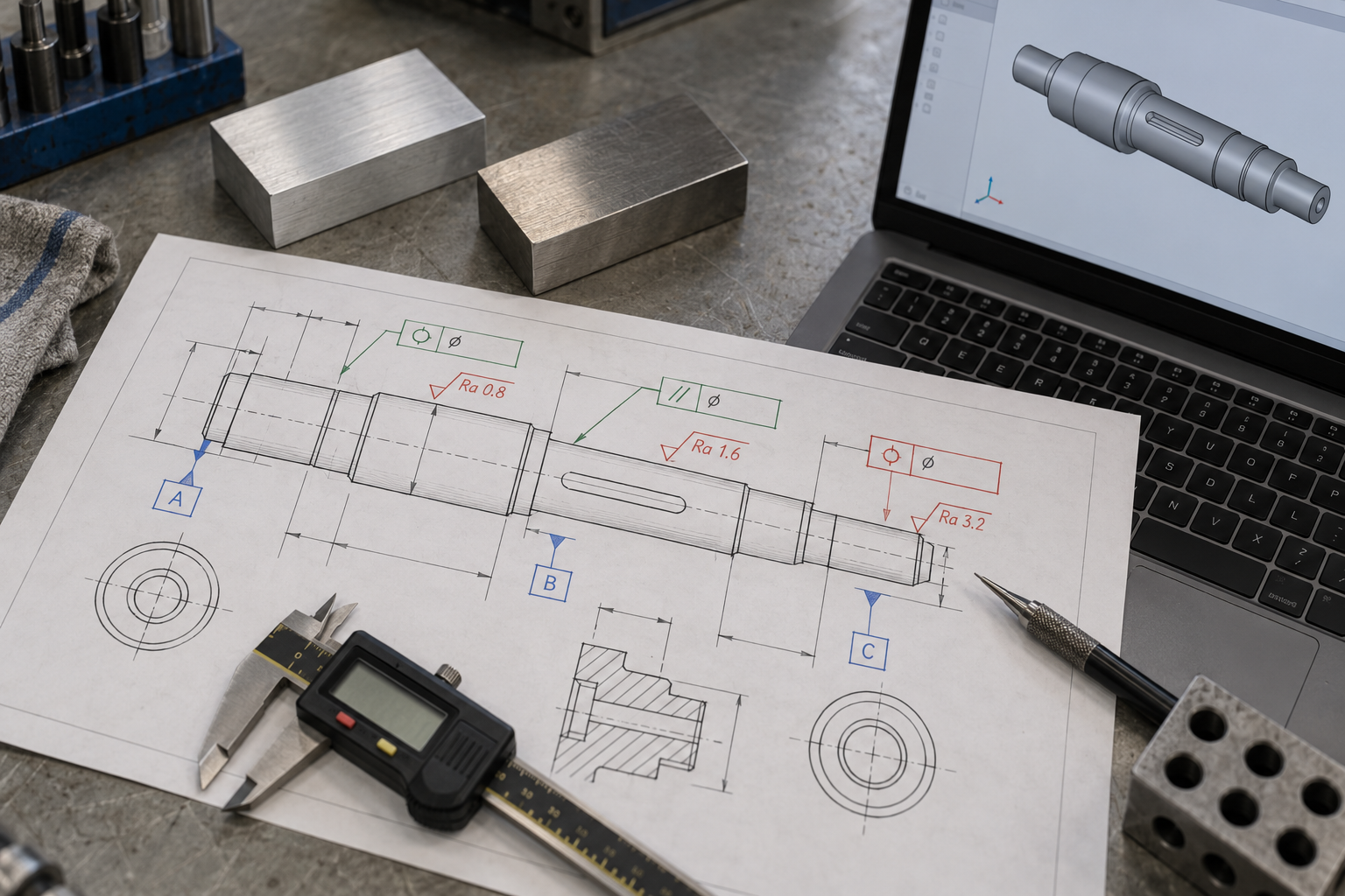
If you want quotes to converge faster, you can upload the drawing, model, and bill of materials directly at the RFQ entry point and fill in all the items above at once. The platform will provide an estimate based on part features and quantity; the specific process and tolerances are still subject to engineering confirmation and the drawing—it doesn't replace the supplier's process judgment, it just aligns comparable inputs first.
One last reminder: treat "what process the supplier will use" as a fixed field in the RFQ. Once you've confirmed whether it's turning, 3-axis milling, turn-mill, or 5-axis, then compare price, number of setups, and inspection plans—only then do the differences between quotes have an explainable basis. If the supplier's process judgment doesn't match your design intent, discuss the geometry and functional faces first, then talk price—this is usually more effective than simply haggling.
Frequently asked questions
The questions below are the points readers most often get stuck on when choosing CNC lathe machining and CNC machined parts; the answers try to return to the judgment logic in this article.
For the same part, why do some suppliers quote a turning price and others a milling price, with differences of several times?
Because the process type is different. Turning rotates the workpiece while the tool stays relatively stationary, suitable for rotationally symmetric parts; milling rotates the tool while the workpiece stays stationary, suitable for prismatic parts or parts with complex curved surfaces. For the same 3D model, if one supplier plans the process as turning and another as 3-axis or 5-axis milling, the machine hourly cost, programming complexity, and number of setups are all different, so quotes naturally diverge. When requesting quotes, asking clearly "what process do you plan to use" is more meaningful than simply comparing total prices.
How do you decide whether a CNC machined part should be turned or milled?
Look at the geometry first: overall rotational symmetry (shafts, pins, bushings, sleeves, rings, threaded connectors) favors turning; non-rotational features (prismatic bodies like brackets, housings, heat sinks, or complex 3D contours) lead to milling. If the part has both a rotational body and lateral holes or flats, consider turn-mill to reduce setups with a single machine. The criterion is geometry, not price.
When designing turned parts, where is cost most easily driven up?
Three common points: sharp internal and external corners, slender parts, and thin walls. Cylindrical tools can't clear sharp internal corners; forcing corner cleanup often requires EDM or extra operations; slender parts tend to rotate unevenly and chatter against the tool during turning; thin walls vibrate or even break under cutting forces. Adding radii, slightly tapering steep sidewalls, and controlling the length-to-diameter ratio is usually cheaper than relying on the process to tough it out afterward.
To make CNC machining quotes from several suppliers comparable, what is the minimum you need to provide?
Six items: part drawing (with tolerances and GD&T), 3D model (STEP/IGES), material specification, quantity, surface finish or special treatment requirements, and application context. If you only provide a 3D model, the supplier can only guess tolerances, guess material, and guess batch size, so quotes differing by several times is normal. Mark datums, critical tolerances, and functional faces clearly so quotes have a basis for comparison.
5-axis or turn-mill costs more per hour, so why is the total price sometimes lower instead?
Because total cost isn't just about machine hourly rates. Five-axis and mill-turn equipment typically cost more per hour than three-axis or pure turning machines, but they can reduce the number of setups, secondary operations, and repeated re-alignment, and parts accumulate less error across multiple setups. For complex parts with both rotational and prismatic features, reducing setups often brings total cost down. Whether it pays off depends on the specific part's feature count and tolerance requirements—it can't be generalized.
Key takeaways
- The fundamental difference between turning and milling is kinematics: in turning, the workpiece rotates and the tool is relatively stationary; in milling, the workpiece is stationary and the tool rotates. This determines the geometry each is best suited for.
- Rotationally symmetric parts should be turned first; prismatic or complex curved surfaces go to milling; when both rotational and prismatic features are present, consider turn-mill.
- Most DFM constraints are determined by tool geometry: cylindrical tools cannot clear sharp internal corners, slender parts tend to chatter, and thin walls deform under cutting forces.
- The premise for comparable quotes is comparable inputs: drawings with tolerances/GD&T, 3D models, material specifications, quantity, surface treatment, and application context. If any one is missing, side-by-side price comparison is difficult.



