What CNC Machining Is Actually Doing: The Three Basic Categories of Actions—Subtractive, Point, and Contour
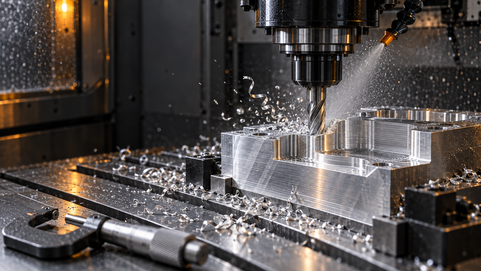
Place a 6061 aluminum plate on a milling machine table, run the program, and the plate ends up with a dozen or so holes, two slots, and a stepped face. This is the most basic form of CNC machining: the tool rotates, the workpiece moves relative to it, and material is removed bit by bit according to the program. To understand it, don't start by memorizing definitions—first look at the three basic categories of actions the tool leaves on the part.
Point Actions: Drilling, Tapping, and Reaming—Solving Hole Position and Hole Diameter
Point actions only require the tool to reach a certain coordinate and then feed along the axial direction; they do not require continuous contour accuracy. Drilling produces a rough hole, reaming smooths it and tightens the hole diameter, and tapping cuts threads into the hole wall. These actions correspond to mounting holes, threaded holes, and pin holes on the part. It is worth noting that drill bits tend to wander, especially in holes with a large length-to-diameter ratio, so positional accuracy is usually secured by drill jigs, center drills, or subsequent boring rather than by the drill bit itself.
Contour Actions: Milling Slots, Pockets, and Side Walls—The Toolpath Determines the Shape
In contour actions, the tool follows a path in the XY plane and steps down in Z to cut slots, pockets, steps, and outer profiles. These actions are relatively sensitive to tool radius, corner radius, and tool deflection at corners. The minimum radius of an internal corner on a part is limited by the available milling cutter diameter—an internal corner marked R2 on the drawing actually requires a cutter below φ4, which reduces tool rigidity, so feed and depth of cut must be kept conservative. Contour accuracy also depends on the machine tool's interpolation and control resolution; it cannot be delivered just by the words "high precision."
Rotational Actions: Turning Outer Diameters, Faces, Grooves, and Threads—Corresponding to Rotational Parts
The workpiece rotates and the tool feeds in a straight line—this is turning. Outer diameters, faces, grooves, chamfers, and threads are all rotational actions. It is naturally suited to parts with a central axis, such as shafts, sleeves, flanges, and fittings. Roundness and cylindricity are usually easier to hold in turning than in milling because the primary motion is continuous and the cutting force direction is relatively fixed. But once a part has an eccentric hole pattern or non-rotational features, the process must be switched, or a turn-mill machine must be used.
Together, the three categories of actions cover the forming needs of the vast majority of metal and plastic parts. What truly distinguishes CNC machining from manual machining is not which tool is sharper, but that the toolpath is controlled by a program and the same block of G-code can be executed repeatedly. This means two things: first, batch consistency comes from the program, not from feel; second, any dimensional change must be made back in the program, tooling, and fixturing, rather than by filing a couple of strokes on the spot.
Common Machine Tool Types and the Geometric Problems Each Solves
Based on geometric requirements, the common division of labor among several types of machine tools is roughly as follows:
- Three-axis vertical milling machine: X, Y, and Z three linear axes. Suitable for machining plate-type parts, single faces or a few faces of box-type parts, and is the starting point for most milling parts.
- Horizontal milling machine: The spindle is horizontal, chip evacuation is smoother, suitable for multi-face machining of boxes, and equipped with a rotary table it can reduce the number of setups.
- CNC lathe: Mainly two axes, dedicated to rotational parts. Models with a subspindle or powered tool turret can complete drilling and flat milling on the back side in a single setup.
- Turn-mill composite: Turning and milling are completed on the same machine tool, suitable for parts that have both rotational contours and eccentric hole systems or milling features, reducing datum conversion.
- Five-axis machine tool: Two rotary axes plus three linear axes, used for impellers, complex curved surfaces, deep-cavity side walls, or parts that require multiple-angle features to be completed in a single setup. What it solves is accessibility and datum unification, which does not mean every part should go on a five-axis machine.
The criterion for choosing a machine tool is not "which one is more advanced," but in how many directions the part's faces and holes are distributed, and whether a single setup is needed to ensure relative position. Few faces and a simple hole system mean three axes are enough; many faces, many angles, and high positional tolerance requirements are when five-axis or turn-mill composite machines come into play.
Structural classification of CNC machining: rotational parts, box-type parts, plate-type parts, thin-wall parts—classify first, then define the process
Before choosing a machine tool, first look at what the part looks like; this is far more reliable than forcing it against an equipment list. The structural classification of CNC machining is not an academic issue—it directly determines whether you should look for turning, milling, or turn-mill composite, and why the number of setups on a quote is two lines instead of one. The common industry practice is to divide parts into four categories by geometry: rotational parts, box-type/housing parts, plate-type parts, and thin-wall and slender parts. Each category has its own main contradiction—rotational parts focus on roundness and coaxiality, box-type parts focus on hole-system position and perpendicularity between faces, plate-type parts focus on flatness and warpage, and thin-wall parts focus on rigidity. If the classification is wrong, all subsequent tolerances, setups, and inspections become remediation.
Rotational parts: why shafts, sleeves, and flanges are prioritized on lathes
For parts such as shafts, sleeves, flanges, and fittings, the main features are cylindrical or conical surfaces that rotate around a centerline. During turning, the workpiece rotates and the tool feeds linearly, naturally generating rotational surfaces; roundness and coaxiality are determined by spindle accuracy and the setup method, which is more direct than milling relying on interpolation to approximate a full circle. Rough machining usually turns the outer diameter first while leaving allowance, and finishing then turns to size; when there are inner-hole and end-face requirements, completing the outer diameter, end face, and inner hole in one setup can reduce datum conversion. For shafts with keyways and cross holes, after turning, go to a milling machine or turn-mill composite to add the features. The criterion is simple: if the part's main functional surfaces are rotational surfaces, consider turning first, and do not start by scheduling three-axis milling.
Boxes and housings: multiple faces and multiple hole systems, the home turf of milling or turn-mill composite
Parts such as boxes, housings, and valve bodies often have multiple machining faces and multiple hole groups, with positional tolerance requirements between holes. The core contradiction of this type of structure is not single-face accuracy, but the relative relationships between faces and between holes. A three-axis vertical milling machine machining multi-face parts requires repeated flipping, and each flip introduces new setup errors; a horizontal machining center or turn-mill composite can complete multi-face machining in fewer setups, making hole-system positional tolerance easier to hold. When choosing, first count the number of machining faces and the directions of the hole systems: if there are precision holes in more than three directions, turn-mill composite or four-axis and five-axis are often more stable than repeated flipping. The common industry practice is to remove material uniformly in rough machining and complete key faces in concentrated finishing within one or two setups.
Plate-type parts: the boundary between milling and sheet metal, and deburring cannot be omitted
For plate-type parts such as panels, brackets, and cover plates, if the thickness is sufficient and there are steps, counterbores, and cavities, CNC milling is more suitable; if it is only a uniform-thickness flat plate plus bending and punching, sheet metal processing is usually more advantageous in cost and efficiency. The boundary is not in the thickness number, but in the structure: those with three-dimensional cavities and requiring strict flatness or mounting-face fit are more controllable by milling; those with pure two-dimensional contours plus bending are more cost-effective with sheet metal. What is easily overlooked for plate-type parts is deburring—edge burrs after milling affect assembly and appearance, and are also exposed during subsequent surface treatment. Writing deburring into the process route is cheaper than reworking afterward.
Thin-wall and slender parts: classified separately because the difficulty is rigidity
Thin-wall parts and slender parts should not be quoted together with ordinary boxes or rotational parts. Their geometry may be very simple, but cutting forces, clamping forces, and residual stresses can all deform the workpiece during or after machining. Thin-wall housings require symmetrical material removal, multiple light cuts, and process bosses when necessary; slender shafts require controlling the tool's radial force, and during turning a steady rest or follower rest may be used for auxiliary support. The first decision for this type of part is not choosing a machine tool, but judging whether rigidity is sufficient and whether the structure should be changed or the operations split. Listing it separately means that when quoting, the labor hours will not be estimated as an ordinary part, and dimensional out-of-tolerance will not be discovered only at delivery.
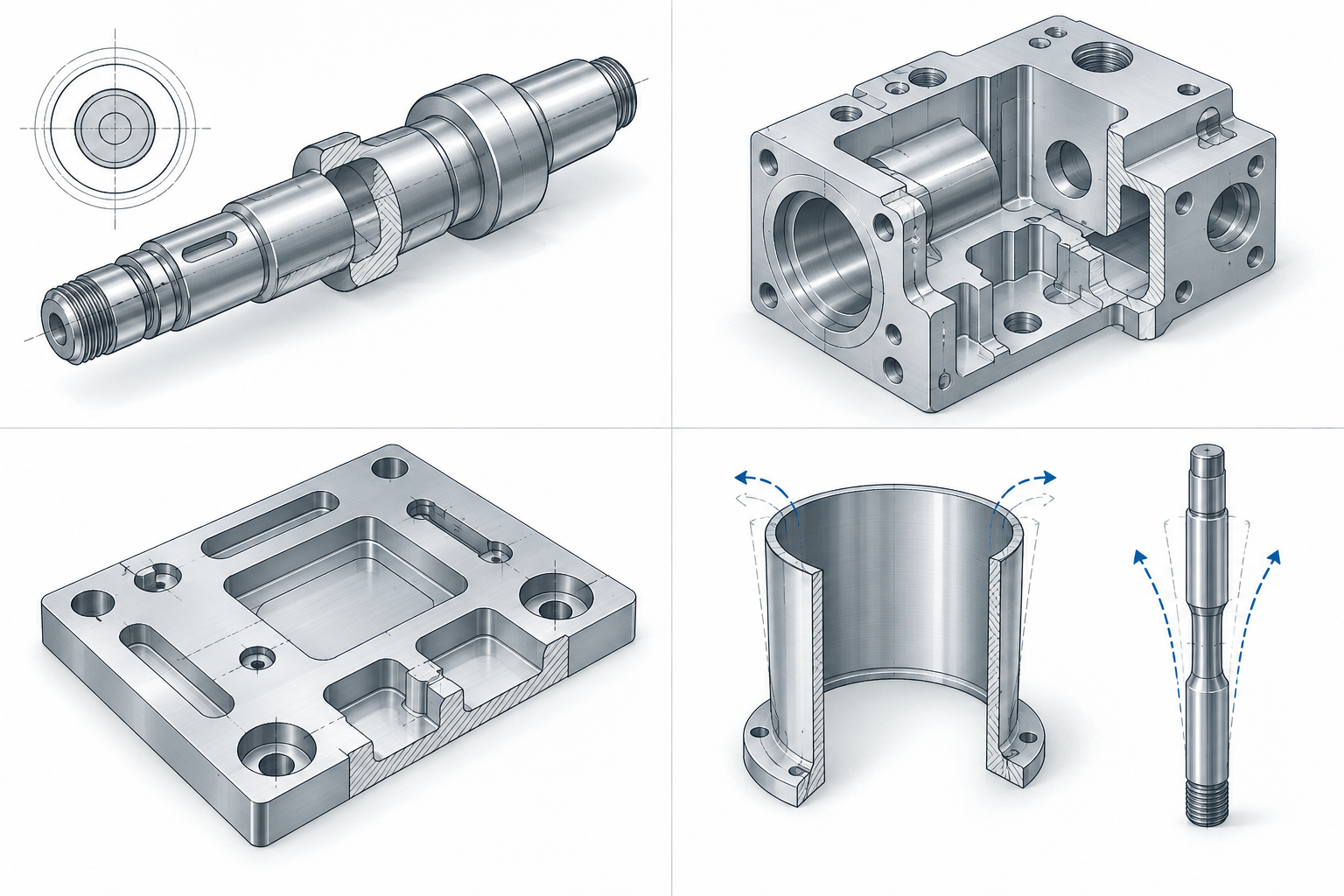
Classifying first and then defining the process has the benefit of avoiding the hidden costs brought by using the wrong machine tool. Giving rotational parts to a milling machine, or giving boxes to three-axis repeated flipping, may still produce a single piece, but the number of setups, datum conversions, and inspection items will all increase, and the tighter the tolerance, the more obvious it becomes. After classification, then look at material, tolerance, and batch size; only then does the process route have a basis for discussion.
How milling, turning, drilling, and grinding divide the work: CNC machining process trade-offs and the boundaries of turn-mill multitasking
The same drawing sent to three factories may yield three different routes: some turn first and then mill, some complete it in one turn-mill multitasking operation, and some simply split the part in two and join it back together. Route differences rarely come from the quality of the machine tools; most come from the judgment of the part geometry. Only when the division of CNC machining operations is thought through clearly can quotes and lead times be comparable.
The four types of operations each handle a segment of features
Milling handles flat surfaces, steps, slots, cavities, and outer contours. The tool rotates and the workpiece feeds, making it suitable for non-rotational open or semi-open features. Turning handles surfaces of revolution—outer diameters, end faces, inner bores, tapers, and threads. The workpiece rotates and the tool moves in a straight line, giving high efficiency and stable dimensions. Drilling and boring are dedicated to hole systems: drilling establishes position, boring corrects size and coaxiality, and reaming handles precision finishing of small holes. Grinding handles two things—high-hardness materials (hardened steel, cemented carbide) and higher surface quality with tighter dimensions. The Ra and cylindricity that fine milling cannot achieve often have to rely on grinding.
The criteria are simple: if there are rotational features and high coaxiality requirements, consider turning first; if hole position is determined by a datum face, consider milling first; if the hole itself requires high precision, add boring or reaming; if hardness and surface quality exceed fine milling capability, schedule grinding.
The value of a single setup, and its boundaries
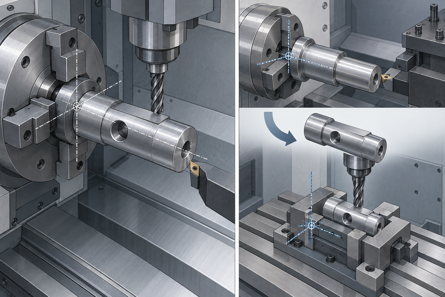
When multiple operations are done on separate machines, each re-clamping re-establishes the datum, and datum conversion errors accumulate. On the same part, the perpendicularity between two faces and the position of two hole groups are often lost to this repeated clamping. A single setup (turn-mill multitasking or a multi-axis machine with a rotary table) completes turning, milling, and drilling in one locating operation, so errors come only from machine geometry and tooling, not from re-clamping.
But turn-mill multitasking is not universal. Its strength is parts such as rotational bodies with eccentric holes, side flats, and helical grooves—the kind of part that is "a turned skeleton plus milled details," for example a flanged shaft with radial holes or a fitting with a side-milled opening. Conversely, pure plate-type parts, large housings, and large parts requiring simultaneous high precision on multiple faces are instead limited in clamping, prone to tool interference, and not cost-effective when forced into turn-mill multitasking; separate machines or a gantry mill are still more suitable. A common industry practice is: if the outer shape is close to rotational and the main features are concentrated in a few orientations, prioritize turn-mill multitasking; if the part size exceeds the machine's rotational range or rigidity is insufficient, split the work.
Three criteria to quickly determine the route
- Hole position takes priority over hole size: the positional tolerance of a hole relative to a datum face is determined by clamping and locating, so consider milling location first, then drilling and reaming; if the hole itself has a tight size, add boring or reaming for correction.
- Perpendicularity and parallelism between faces: if these are to be guaranteed by a single setup, use turn-mill multitasking or a machine with a rotary table; if they are to be guaranteed by separate machines plus a precision datum, then reserve a precision datum face and clamping points.
- Whether there are rotational features: if there are and coaxiality requirements are high, use turning as the base; if not, do not force it onto a lathe just to save effort, because rotational fixtures instead limit accessibility.
Only after the division of operations is settled does it make sense to discuss material machinability, tolerance grading, and clamping methods—because under different routes, the tolerance achievability and inspection methods for the same drawing are different. Material and tolerance come next; do not reverse the order.
How to choose CNC machining materials: machinability differences among aluminum, stainless steel, brass, and engineering plastics
If the material is chosen wrong, every subsequent step in CNC machining is paying off the debt. Changing the grade on the same drawing changes tool life, cutting parameters, clamping method, and even whether stress relief is needed. The recommended order of judgment is: first look at function (strength, corrosion resistance, insulation, weight), then machinability, and finally condition and post-processing.
Aluminum: the trade-off between 6061 and 7075 is not just about strength
6061-T6 is the most worry-free aluminum in CNC machining. It has low cutting resistance, smooth chip evacuation, and thin-walled parts are less likely to spring, while its appearance after anodizing is also stable. It is suitable for parts such as enclosures, brackets, and fixtures that need both rigidity and rapid iteration. 7075-T6 has noticeably higher strength, but also higher hardness and residual stress, making it more prone to warping during thin-wall or large-area material removal; before finishing, it often needs stock left and material removed in stages. A common industry practice is: use 7075 for load-bearing parts, and 6061 for general structural and appearance parts; confirm the specific grade and temper according to the drawing, and do not place an order with just the word "aluminum."
Stainless Steel: The Work-Hardening Trap of 304 and 316
The difficulty with 304 and 316 isn't hardness—it's work hardening. When the tool dwells on the surface or rubs repeatedly, the surface layer gets harder the more you cut, making the next cut even harder, creating a vicious cycle. The countermeasures are low feed, large depth of cut, sharp tools, and ample cooling to avoid "rubbing" the tool. Because 316 contains molybdenum, it has better corrosion resistance, but its machinability is usually a bit worse than 304. For stainless steel parts with tight tolerances and high surface requirements, separating roughing and finishing and changing tools promptly is more effective than adjusting parameters. Whether solution treatment or stress relief is needed should be confirmed according to the drawing and application.
Brass and Engineering Plastics: Good Machinability, but Each Has Hidden Constraints
Brass (such as free-cutting brass like HPb59-1) has excellent machinability and is suitable for small parts, fittings, and electrodes, but weight and material cost must be weighed, and differences in lead content among grades can affect subsequent surface treatment and compliance. Among plastic parts, POM is dimensionally stable and easy to machine, suitable for gears and sliders; PEEK is heat- and chemical-resistant but expensive and prone to stress during cutting; PA (nylon) changes dimensions after absorbing moisture, and thin-walled parts can deform under even slightly too much clamping force. For plastic parts in CNC machining, special attention must be paid to clamping force and cutting heat; letting the part rest for a period after roughing before finishing is often more stable than forming it in one pass.
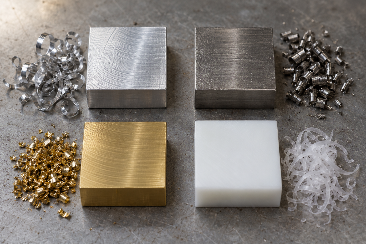
One final reminder: the same grade in different tempers varies greatly. 6061 in T6 versus O temper, stainless steel solution-treated versus annealed, and plastics extruded versus molded all change machinability and deformation tendency. Writing the grade plus temper on the drawing saves a round of rework compared with writing only "aluminum" or "stainless steel." The material library and material guide can be used to compare the applications of common grades, but the drawing callouts remain the final authority.
How to Set CNC Machining Tolerance Bands: Graded Callouts for Functional, Mating, and Non-Functional Surfaces
The thing most likely to get out of control on a drawing isn't the number of dimensions—it's how tolerances are assigned. The tolerance band in CNC machining is essentially a translation of "what this surface is for": mating surfaces, guiding surfaces, and sealing surfaces each carry different responsibilities, and blanket-labeling everything ±0.01 or leaving everything to general tolerances will cause problems in quoting and execution. A common industry practice is to separately tolerance only the dimensions that affect assembly and function, leaving the rest to the unspecified tolerance table; but the specific values still depend on part function, fit type, and machine capability, and should be confirmed according to the drawing rather than copying a number. Tolerances are also not better the tighter they are. Tightening by one grade often means one more finishing pass, one more setup, or switching to grinding, and the cost increase is usually non-linear.
Mating Surfaces, Functional Surfaces, Non-Functional Surfaces: The Three-Tier Approach to CNC Machining Tolerances
If you first classify every dimension of a part into three tiers, tolerance callouts have a basis. Mating surfaces (bearing seats, pin holes, locating spigots, seal grooves) directly determine whether assembly can be achieved, and are usually given tighter dimensional tolerances and geometric tolerances; functional surfaces (guideway surfaces, mounting datum surfaces, load-bearing contact surfaces) affect performance, with the focus on form and orientation tolerances such as flatness and parallelism rather than individual dimensions; non-functional surfaces (outer contours, non-mating counterbores, decorative surfaces, handles) only require "no interference and no sharp edges," so general tolerances suffice. The point of grading is to concentrate machining resources on the surfaces that truly matter and relax the rest.
A practical criterion: if a dimension being out of tolerance would cause assembly difficulty, functional failure, or customer complaints, tolerance it separately; if it merely "looks a bit off," leave it to the unspecified tolerances. The problem with many drawings is exactly the opposite—key holes have no position tolerance, while unimportant outer shapes are given very tight linear tolerances.
Linear Tolerances vs. Geometric Tolerances: Why Position and Perpendicularity Are Harder Than Dimensions
Linear tolerances (such as 20±0.05) govern the size of a dimension, while geometric tolerances govern form and relative relationships. Requirements such as parallelism, perpendicularity, coaxiality, and position are more affected during machining by fixturing, datum transfer, and tool deflection, and their inspection relies more on datum plates and CMMs. Position is especially common: specifying the relative positions of multiple holes with a datum-referenced position tolerance is clearer than labeling each hole distance individually and is closer to assembly requirements. How the datum is chosen directly determines whether inspection can be reproduced—the datum should be the surface or hole that actually contacts during assembly, not just any machining datum picked at random.
Surface Roughness Ra and Machining Methods: What Precision Milling and Grinding Each Cover
Ra and tolerance are two different dimensions and cannot substitute for each other. Ordinary milled surfaces commonly fall in the Ra 1.6–3.2 μm range; precision milling with finer feed and higher spindle speed can achieve around Ra 0.8 μm; grinding is used for lower Ra and harder materials, commonly reaching Ra 0.4 μm or even lower in the industry, depending on the material and process combination. When specifying Ra, ask yourself: is this surface a sealing surface, a sliding surface, or merely an appearance surface? Sealing and sliding surfaces are worth specifying Ra separately; if an appearance surface is only for looks, the difference is often covered after sandblasting or anodizing, so there is no need to add a finishing operation for it.
If a part involves both turned surfaces of revolution and milled hole patterns, it is best to clarify the tolerance grading before quoting, since the process route will follow directly from it. For tolerances and surface requirements involving a specific drawing, you can compare the machinable range on the CNC machining capabilities page, then decide which surfaces to leave to general tolerances and which to tighten separately.
CNC Machining Fixturing and Deformation Control: Common Approaches for Thin Walls, Slender Parts, and Deep Cavities
How to choose a fixture: applicable scenarios for vises, soft jaws, vacuum chucks, clamps, and dedicated fixtures
Thin-walled and slender parts: symmetrical material removal, multiple light cuts, leaving process bosses
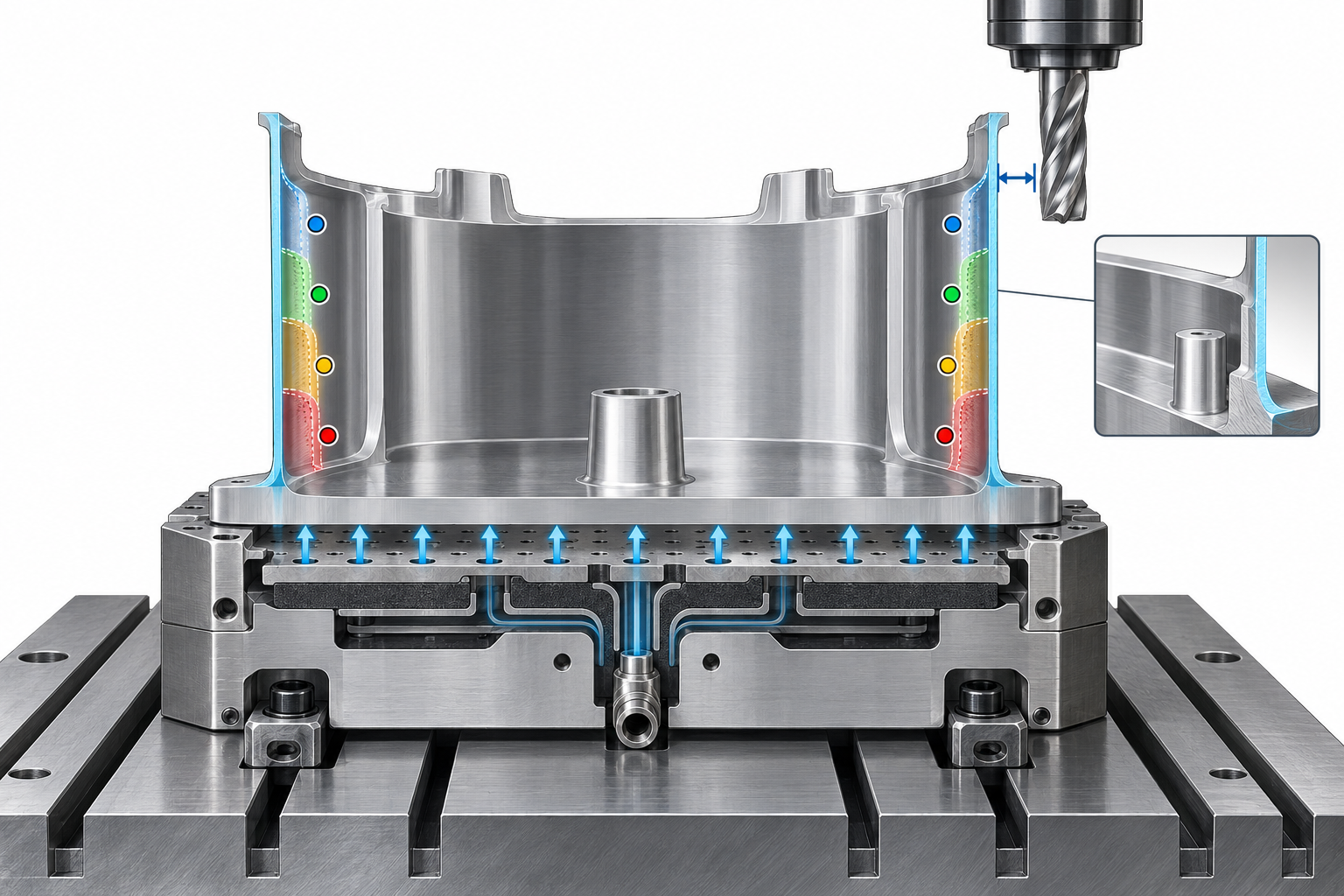
Deep cavity machining: tool overhang, tool deflection, and chip evacuation
Stress relief and removal sequence: should you stop after rough machining?
CNC machining inspection and the checklist to confirm before quoting
A part being made does not mean it can be delivered; in between there is an inspection step. A part being quotable does not mean it is quoted correctly; in between there is a clearly stated requirement. These two things are connected in CNC machining: how you define acceptance directly determines what measuring instruments the manufacturer uses and whether a CMM is needed, and both instruments and time go into cost. So discussing inspection methods together with the information needed for quoting is closer to the actual process than discussing them separately.
Each measuring instrument covers a certain range: what to use to measure CNC machining dimensions, and to what extent
Measuring instruments must match the feature being measured; choosing the wrong instrument is not a precision problem, it is a problem of not being able to measure it.
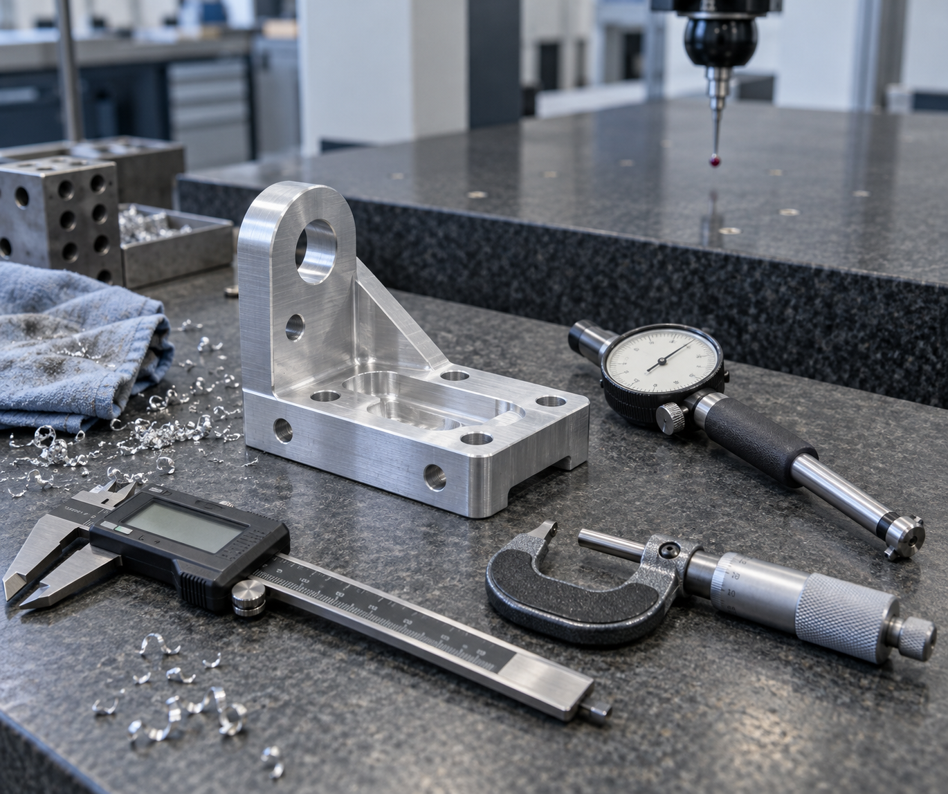
- Calipers: outer diameter, inner diameter, steps, depth; fast, suitable for on-site sampling inspection of general-tolerance dimensions. When measuring groove inner diameters and narrow slots, readings are affected by the jaws; do not rely only on calipers for out-of-tolerance disputes.
- Micrometers: single-point dimensions such as outer diameter, plate thickness, and wall thickness; high resolution, but they measure only one direction, so form errors must be pieced together from multiple point measurements.
- Bore gauge (cylinder gauge): measures a hole's inner diameter and cylindricity, suitable for mating holes. Zero it with a ring gauge or standard before use, otherwise readings will be consistently off.
- Coordinate measuring machine (CMM): geometric tolerances such as position, perpendicularity, parallelism, and coaxiality, as well as the relative relationships between hole patterns. A CMM measures points in a coordinate system, so how the datum is established directly determines the conclusion.
- Vision measurement: small parts, thin sheets, contour edges, punched or etched profiles; non-contact, no deformation from pressure, but it cannot measure in the depth direction.
- 3D scanning: overall contour comparison, deviation color maps of first articles versus CAD, reverse modeling. Suitable for seeing trends and overall form, not suitable as the direct arbitration basis for a single dimension.
Information to provide before a CNC machining quote: miss one item and the price deviation can be several times over
- Material grade and condition: 6061-T6 and 6061-O have different cutting feel and distortion tendencies, and different prices; writing only "aluminum" is as good as writing nothing.
- Key tolerances and datums: which dimensions are mating surfaces, which follow general tolerances, and which features carry geometric tolerances. For dimensions not marked on the drawing, the manufacturer works to general tolerances, and later disputes have no basis.
- Surface treatment: anodizing, bead blasting, electroplating, and passivation affect dimensional allowance and process sequence, and also affect whether a process clamping surface must be left.
- Quantity and batch: single piece, small batch, and mass production have completely different cost structures, and the degree to which setup costs are amortized differs greatly.
- Inspection requirements: whether a first article report, a CMM dimensional report, or material certification is required—these are all billed as separate labor hours.
- Delivery expectations: not to make the manufacturer commit, but to let the manufacturer judge whether scheduling and the process route are feasible.
CNC machining FAQs: several high-frequency questions from selection to implementation
These questions mostly come up between drawing review and quote back-and-forth. The answers follow the criteria earlier in this article; where specific values and lead times are involved, room has been left—the drawing callouts and the machinist's confirmation are final.
For the same part, how do you decide whether it should be turned or milled?
First check whether there are rotational features. For parts like shafts, sleeves, and flanges that are mainly cylindrical surfaces, end faces, and threads, turning can produce most surfaces in a single setup with fewer datum transfers; for box-type, housing, and plate-type parts with multiple faces and hole systems, milling or turn-mill is more suitable. If both rotational and non-rotational surfaces make up a significant proportion, then consider turn-mill, but see whether the hole position tolerance and face-to-face perpendicularity are worth paying the cost for a single setup. The criterion is geometry, not habit.
For CNC machining tolerances, is tighter always better?
No. Tolerances are graded by function: mating surfaces such as bearing seats and pin holes get tight tolerances, while non-mating surfaces are relaxed to general tolerances. Tightening everything across the board only drives up setup, tooling, and inspection costs, and may introduce new errors through repeated alignment. Also, distinguish between linear tolerances and geometric tolerances—parallelism, perpendicularity, and position control direction and location, which dimensional tolerances alone cannot manage. Specific values are confirmed according to the drawing and function; a common industry practice is to call out only critical dimensions.
Why do thin-walled parts deform easily, and how should fixturing handle it?
Deformation mainly comes from two sources: cutting force and clamping force. The thinner the wall, the lower the rigidity; a single vise clamp can cause the workpiece to deflect or spring back. Common practices are symmetric material removal, multiple light cuts, leaving process tabs, and after roughing, letting the part rest or stress-relieving before finishing; for clamping, switch to soft jaws, vacuum chucks, or dedicated fixtures to distribute the force to more rigid areas. For deep cavities, also watch tool overhang—the longer the overhang, the more easily the tool deflects.
What is the minimum information to provide before quoting?
Material grade and condition, critical tolerances, surface treatment, quantity, inspection requirements, and expected lead time—if any one of these six is missing, the quote will likely go back and forth. The number of setups, tool changes, and inspection methods have a big impact on cost, and these all depend on the information above. Marking datums and critical dimensions clearly on the drawing saves trouble compared with explaining afterward. When the information is complete, the quote is closer to the real machining path.
How do you choose between CNC machining, 3D printing, and sheet metal?
Look at shape, batch size, and material. For complex internal cavities, lightweight structures, and small-batch prototyping, 3D printing iterates quickly; for uniform-thickness sheet parts, bent brackets, and enclosures, sheet metal saves material and suits batch production better; for mating surfaces, threads, and high-rigidity structures that need solid metal, CNC machining is more reliable. The three are not substitutes; many projects first use 3D printing or CNC for samples, then switch to sheet metal or injection molding. When choosing, first ask what this part relies on for load bearing and for locating.
Key takeaways
- First define the structural classification (rotational parts/box parts/plate parts/thin-wall parts), then decide the machine tool and process sequence—this saves more trouble than quoting the material first.
- Tolerance zones should be specified item by item according to functional surfaces; relaxing non-functional surfaces leaves margin for tooling and fixturing, and cost often hinges on the number of setups.
- The difficulty with thin-wall and slender parts is not the cutting itself, but tool deflection, fixturing deformation, and stress relief; the industry commonly controls these with multiple light cuts and symmetric material removal.
- Before quoting, provide the material grade and temper, key tolerances, surface roughness, quantity, and inspection method together to reduce back-and-forth.
- Any precision and lead time must be confirmed according to the drawing, material, and quantity; the figures in this article are only common industry references.



