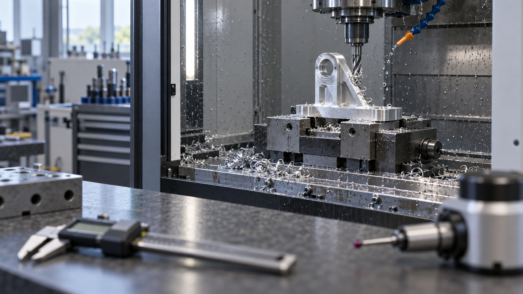
Where exactly is CNC precision part machining "precision"
Material and Structure: The First Gate Determining the Achievability of CNC Precision Part Machining
Many drawings are judged "expensive" or "impossible" at the quoting stage, usually not because equipment accuracy is insufficient, but because the material and structure themselves limit the achievability of CNC precision part machining. On the same machine, milling a block of 6061 aluminum versus milling a block of 304 stainless steel yields completely different dimensions, surfaces, and efficiency that can be stably produced. When reviewing a drawing, look at these two items first—more practical than first asking how many axes are used.
Material Machinability: Cutting Feel Determines Surface and Burrs
The industry often divides materials into "easy to cut" and "hard to cut," judged by chip form and tool life. Aluminum alloys (6061, 7075) produce crisp chips, evacuate easily, and finish milling usually achieves better roughness; free-machining steel (such as 12L14) has sulfur or lead added, chips break well and dimensions are stable, but weldability and corrosion resistance are poor—check the application before choosing. 304 stainless steel has high toughness and work-hardens quickly, tool wear is fast, and dimensions tend to drift in the mid-to-late batch—the first piece passing does not mean the fiftieth piece passes. Copper and copper alloys conduct heat well but are sticky, chip evacuation in narrow slots and deep cavities is difficult, and surfaces are easily scratched twice. Engineering plastics (POM, PEEK, nylon) have low cutting forces, but even slightly higher clamping force deforms them, and PEEK is expensive with high trial-cut costs.
These differences ultimately show up in two or three things: whether the drawing roughness can be stably achieved, whether burr form is controllable, and which way dimensions drift after tool wear in a batch. The drawing only specifies "Ra 1.6," but the actual difficulty of achieving it differs by material.
Thin Walls, Deep Cavities, Slender Shafts, Narrow Slots: Difficulty Lies in Structure-Fixturing Coupling
These four types of structures are difficult not just because cutting forces are large, but because structure and fixturing constrain each other.
- Thin wall: The smaller the wall thickness-to-height ratio, the worse the rigidity. Common industry experience is that when wall thickness is below 1 mm and height exceeds 10 times the wall thickness, both cutting force and clamping force easily cause tool deflection and chatter; whether it can actually be done depends on material, wall thickness uniformity, and support method.
- Deep cavity: When the deep cavity length-to-diameter ratio exceeds 3–4 times, tool holder rigidity drops and chip evacuation becomes difficult, requiring extended tools or layered machining, and surface quality drops noticeably.
- Slender shaft: During turning the workpiece deflects; the larger the length-to-diameter ratio, the more it relies on a steady rest or follower rest, otherwise the middle dimension will be oversized or taper will appear.
- Narrow slot: Slot width determines tool diameter; the thinner the tool, the easier it breaks, feed must be slowed, and the slot bottom fillet is also limited by tool radius.
These issues must be flagged during drawing review: can the structure be changed, can it be made in pieces, can the material be changed. Discovering them at the fixturing stage means rework costs have already gone up.
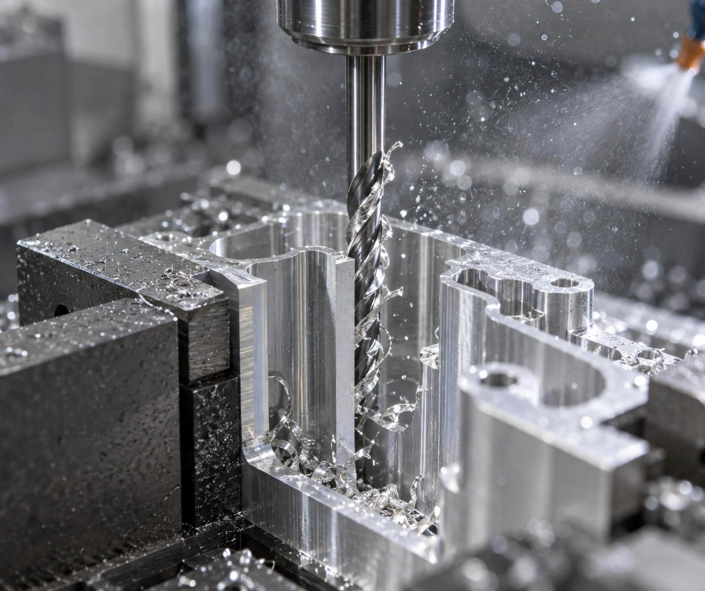
Material and structure are viewed together because they jointly determine the difficulty of subsequent fixturing, tooling, and inspection. A 304 stainless steel cavity with 2 mm wall thickness requires more consideration of heat treatment for stress relief, symmetric material removal, and more conservative cutting parameters than an aluminum part of the same structure. Do this step first when reviewing a drawing, and the subsequent process route becomes meaningful. If you're unsure which category your part falls into, take the drawing and critical dimensions to the CNC machining capabilities page to compare against the process range, then decide whether to adjust the structure or material.
Fixturing and Datums: The Most Underestimated Cost Point in Precision Part Machining
In a CNC precision part machining quote, fixturing is rarely listed separately, but it is often the watershed between achieving tolerances and scrapping them. On the same machine, same tool, same parameter set, changing the fixturing method can shift dimensions by a whole tolerance band. Fixturing must answer three questions: how many faces can be done in one setup, how many datum transfers occur, and whether clamping force will deform the part. If these three aren't resolved, no amount of refinement in tooling and programming later can compensate.
The core principle is just one sentence: datum unification. Design datum, machining datum, and inspection datum should fall on the same face as much as possible. Every flip adds one alignment error, one clamping deformation, one tool mark. It can be roughly considered that number of setups ≈ number of error accumulations—not linear addition, but each additional setup adds one more link of accumulable deviation in the dimension chain. For multi-operation parts, it's better to spend extra time making soft jaws or dedicated tooling than to repeatedly flip, and this is why.
How Many Faces Can Be Done in One Setup: Look at Part Geometry First, Then Machine Travel
A 3-axis machine in one setup typically only machines the upward-facing face; five faces require at least two setups; a 4-axis with one rotary axis can complete adjacent side faces in one setup; 5-axis simultaneous further reduces flips, but at the cost of more complex programming and tooling. A reminder here: 5-axis is not a necessary condition for precision part machining; it solves "positional relationships between faces" and "reducing setups," not making the tolerance itself smaller.
Applicable Boundaries of Common Fixturing Methods
Different methods have clear boundaries, and mixing them causes problems:
- Vise + parallel blocks: Suitable for regular blocks, small-to-medium batches. Advantages are speed and versatility; disadvantages are clamping force concentrated on both sides, thin-wall parts easily pressed into a barrel shape, and uneven block heights causing non-perpendicular sides.
- Soft jaws: Turned to fit the part contour, clamping force is distributed, positioning repeatability is good, suitable for parts with rotational features or requiring secondary setups to maintain coaxiality. Soft jaws themselves must be re-turned, a one-time investment that pays off more with larger batches.
- Vacuum chuck: Suitable for thin plates and large flat parts, clamping force is uniform and introduces almost no lateral deformation. The boundary is that the part must have a certain area and a flat bottom; heavy roughing with large cutting forces won't hold.
- Wax bonding / low-melting-point alloy: Suitable for thin-wall, irregular, or parts without suitable clamping surfaces, supported by the entire bottom face. Disadvantages are time-consuming removal and cleaning, and being affected by cutting heat, it cannot be used for heavy cutting.
- Dedicated tooling: When batch size, precision, or shape complexity reaches a certain level, dedicated tooling is the only stable solution. It separates positioning and clamping in design, usually paired with one face and two pins or three-point locating.
Clamping Force and Deformation: The Most Commonly Overlooked Link in Fixture Design
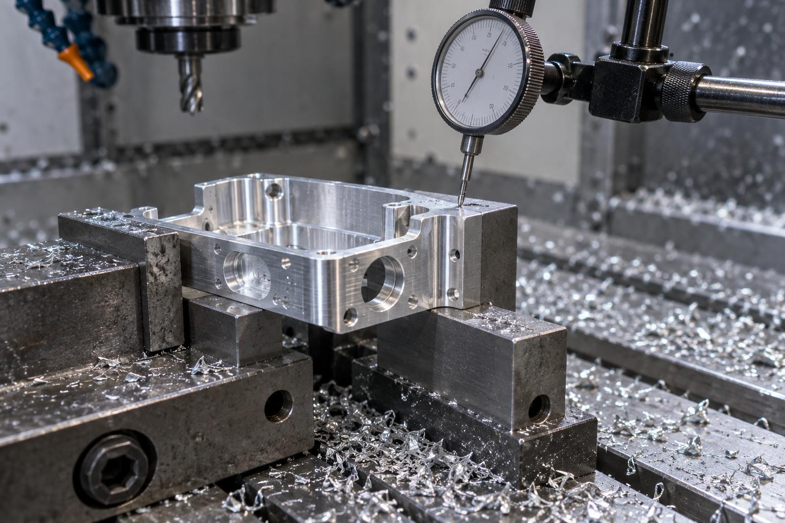
Clamping force direction should align as much as possible with the main cutting force direction and with the direction of best part rigidity. A common approach for thin-wall parts is "clamp lightly first, machine, then release and re-measure," or confirm deformation with a dial indicator in the free state. Common industry judgment is that if clamping deformation approaches or exceeds 1/3 of the tolerance band, the fixturing scheme should be changed rather than forcing it by adjusting parameters. This ratio is only an empirical reference; specifics depend on material, wall thickness, and drawing requirements.
Tooling, cutting parameters, and surface roughness: keeping the tolerance band intact
The drawing specifies ±0.02, and the machine's positioning accuracy is sufficient, yet the part comes out oversized one moment and undersized the next, with tool marks on the surface—the problem is often not the machine, but the tooling and cutting parameters. In CNC precision part machining, whether the tolerance band holds depends on how tool geometry, feed per tooth, and depth of cut are matched. Get the parameters wrong, and even the best machine will just consistently produce scrap.
Why finishing uses small depth of cut, high spindle speed, and low feed
The goal of roughing is to remove material; the goal of finishing is to control dimensions and surface finish. So finishing typically presses radial depth of cut down to 5%–10% of the tool diameter, adjusts axial depth of cut according to the tool's length-to-diameter ratio, raises spindle speed to the upper limit allowed by the tool and material, and lowers feed per tooth. The reason is straightforward: with a small depth of cut, cutting force is small, so tool and workpiece deflection is small, and the probability of the dimension landing in the middle of the tolerance band is higher; with high speed and low feed, the chip thickness per tooth is thin, the residual height is small, and surface roughness is naturally good.
But this is not an iron law. Aluminum alloy can take high speed and high feed because cutting force is small and chip evacuation is good; stainless steel and titanium alloy have poor thermal conductivity, so too high a speed causes the cutting edge to wear rapidly—instead you need to reduce speed, add cooling, and control feed per tooth so it is not too small, avoiding the edge rubbing against the hardened layer. Parameters are a compromise among material, tool coating, and machine rigidity; copying someone else's parameter table usually does not work.
Surface quality differences between ball-nose and flat-bottom tools on curved surfaces
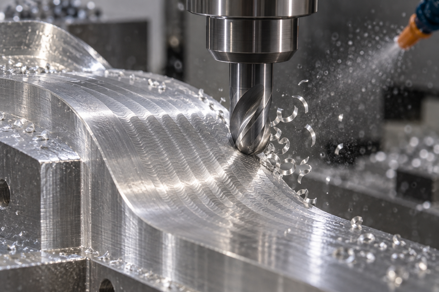
A flat-bottom tool travels on a flat surface, and the contact between the tool bottom and the workpiece is a line, so residual height is low and the surface is uniform. A ball-nose tool travels on a curved surface, and the contact point is a point, so scallop-shaped residual height is inevitably left between adjacent tool paths; the denser the stepover, the lower the residual, but machining time rises linearly. Therefore, the surface roughness of curved-surface finishing is largely determined by stepover and tool radius, not by spindle speed. If you want good Ra without grinding, calculate the stepover accurately, or switch to a larger ball-nose tool radius—the larger the radius, the smaller the residual height at the same stepover.
Common industry references: finish milling aluminum alloy can reach a surface roughness on the order of Ra 0.8–1.6 μm, and finish turning of outer diameters can also achieve a similar level; stainless steel and titanium alloy, because the material is sticky and tools wear quickly, are usually one grade worse under the same parameters, and achieving Ra 1.6–3.2 μm is more realistic. These numbers are only a basis for judgment, not a promise—actual results depend on material condition, tool grade, cooling method, and machine rigidity, and should be confirmed against the drawing before quoting.
Tool deflection, tool wear, and batch consistency
The tool bends under cutting force, which is called tool deflection. The direction of deflection determines whether the dimension is oversized or undersized: in outer-diameter turning, deflection makes the diameter oversized; in boring, deflection makes the hole diameter undersized; in milling a side wall, deflection makes the wall thickness thicker. Slender tools, large overhang, and large depth of cut all amplify deflection. The approach is to reduce overhang, take light layered cuts, and use cutter compensation for fine adjustment when necessary.
Tool wear has an even greater impact on batch consistency. The first part passing does not mean the hundredth part will pass—after flank wear increases, cutting force rises, the amount of deflection changes, and dimensions slowly drift. For batch parts, a tool change strategy must be defined: change tools by cutting time, by number of parts, or by online measurement feedback. During continuous machining, sample the first few and last few parts; if dimensions drift in one direction, suspect tool wear first, then thermal deformation.
Heat, chips, and residual stress: the invisible dimensional drift in precision part machining
In CNC precision part machining, the most easily overlooked source of error is not that the machine is not good enough, but heat, chips, and residual stress. They do not show up on the drawing tolerance band, yet they can push dimensions out of tolerance after the clamp is released, the part cools, or even after sitting overnight. Below, in the order of “heat → chips → stress,” we explain how each type of drift occurs and how to control it.
Cutting heat: why dimensions measured right off the machine “shrink back”
When the temperature in the cutting zone rises, both the workpiece and the tool expand. The thermal expansion coefficient of aluminum is about 23×10⁻⁶/°C, and steel about 11–12×10⁻⁶/°C. For a 100 mm aluminum part with a 10 °C temperature rise, the length can increase by about 0.02 mm—this already eats up a lot of the tolerance margin on precision parts. Right off the machine, the part is hot and the dimension is oversized; after cooling to room temperature it contracts, and a dimension that was “just barely acceptable” may sit at the lower limit or even go out of tolerance.
Practical approaches are: separate roughing and finishing, and let the part return to near room temperature before finishing; during finishing, control coolant flow rate and direction so local areas do not alternate between hot and cold; for thin-wall and long-overhang structures, rather reduce the depth of cut per pass and increase the number of passes than use large cutting forces for efficiency. Thermal drift cannot be completely eliminated, but it can be pushed into the corners of the tolerance band.
Chip evacuation: poor chip removal causes both scratches and tool deflection
If chips cannot be evacuated, they crowd between the tool and the machined surface. In mild cases they press scratches into the finished surface; in severe cases they push the tool off course, causing deflection—the toolholder deviates from the theoretical path under force, and the actual cut dimension is oversized or undersized relative to the set value. Deep cavities, narrow slots, and blind holes are especially prone to this: chips go in but cannot come out, and coolant cannot wash them away either.
Common countermeasures include: selecting a suitable groove shape and rake angle for the material so chips break cleanly; using high-pressure internal cooling or directed cooling to flush chips away from the cutting zone; using layered, helical plunging for deep-cavity parts to avoid cutting to full depth in one pass; and, when necessary, stopping mid-process to blow out chips. There are no universal parameters here; they must be adjusted together according to material, tool, and cavity depth. A common industry practice is to keep the length-to-diameter ratio of deep cavities within 3–4 times for more stable chip evacuation; beyond this range, the process needs dedicated discussion, and specifics should still be based on the drawing and actual trial cuts.

Residual stress: why symmetric material removal and intermediate stress relief are worth the extra time
Bar stock and plate carry internal stress from rolling or extrusion. When roughing removes a large amount of material from one side, the stress balance is broken, and the part bends or twists toward the side where material was removed. During finishing it is held down by the fixture, and measurements show it is acceptable; once released and left to sit, the stress redistributes and the dimensions change. This is the typical reason thin-wall parts are “acceptable off the machine, out of tolerance overnight.”
There are several practical approaches: leave time for natural aging between roughing and finishing so stress is released first; for demanding parts, arrange stress-relief annealing or vibratory stress relief; during roughing, remove material symmetrically, cutting alternately on both sides rather than hollowing out one side in one go; and use small depth of cut and multiple passes in finishing to reduce new stress introduced each time. These approaches all increase labor hours, so judgment must be made at the drawing stage: does this part really need to be this stable, or can the tight tolerances be concentrated on mating surfaces while the rest are relaxed.
Looking at these three types of drift together, the logic is consistent: temperature, chip evacuation, and stress all cause actual dimensions to deviate from programmed dimensions, and they often only become apparent after measurement. Controlling them does not rely on the accuracy of a single machine, but on process arrangement—separation of roughing and finishing, stable cooling, smooth chip evacuation, and symmetric material removal. To judge which type of risk your part falls into, you can first compare material and structural ranges on the CNC machining capabilities page, then decide whether a dedicated discussion of the process route is needed.
Inspection and first article: proving that CNC precision part machining truly meets spec
Choose the wrong measuring instrument, and the dimensions in CNC precision part machining are measured in vain
What first article, in-process sampling, and final inspection each cover
Mismatch between inspection fixtures and drawing requirements is a common source of disputes
- Critical dimension list: mark which are mating surfaces and which are general tolerances, so inspection does not apply equal effort everywhere.
- Datum confirmation: whether the datums in design, machining, and inspection are unified; if not, clarify first.
- Tolerance and measuring instrument matching: use micrometers and CMMs for tight tolerances, do not make do with calipers.
- Surface and deburring: check roughness against drawing requirements; sharp edges, burrs, and rolled edges should be listed separately.
- Material and certification: request material grade, condition, and batch certificates as needed; do not assume they are available.
- Form of inspection report: Whether a first article report, full dimensional report, or CMM report is required should be agreed in advance.
Cost-driven tolerance trade-offs: what should be discussed before quoting CNC precision parts machining
Marking tolerances on a drawing is an expression of design intent; but on the machining side, tightening each tolerance grade consumes machining hours, tool life, and inspection resources. The bulk of the cost in CNC precision parts machining is not in the material, but in “the extra operations spent to hold that dimension.” Before quoting, clarifying which tolerances on the drawing are truly needed and which can be relaxed is often more effective at reducing cost than switching suppliers.
Tighter tolerances are not always better: first identify the mating faces
A common practice is: only the faces that truly participate in mating, guiding, or sealing keep tight tolerances, while the remaining non-mating faces follow general tolerances. Marking every dimension on a part as ±0.01 mm often results in the machining side being forced into full-size finish milling and repeated measurement; costs go up, yet assembly does not become smoother because of it.
- Mating faces, bearing seats, seal grooves: keep the tight tolerances from the drawing; this is the functional baseline.
- Outer contours, non-mating steps, installation clearance faces: common industry practice is to relax them to the ±0.1 mm level, subject to confirmation against the drawing and application scenario.
- Free-form surfaces and appearance surfaces: the focus is surface roughness, and dimensional tolerances can be appropriately relaxed.
Machining costs determined by structural details
If a fillet radius is written as a non-standard value (for example, R1.7), the machining side must prepare a dedicated tool for it or run a form tool path, and the quote naturally rises. Changing it to match an existing standard tool radius (R1, R2, R3) usually does not change function, but saves tooling and tool-change time. Deep cavities and narrow slots are another type of cost multiplier: deep cavities require long overhang tools, rigidity decreases, and feed must be reduced to avoid chatter marks; narrow slots limit tool diameter, make chip evacuation difficult, and easily cause secondary scratches.
Before quoting, it is recommended to confirm these items: material grade and condition, blank form (plate/bar/forging/casting), critical tolerances and their datums, surface roughness requirements, and the nature of the batch and delivery schedule. The more complete the drawing information, the more closely the machining side can provide a price that reflects reality, rather than relying on adding safety margin as a fallback.
The relationship between batch size, delivery schedule, and cost
Single pieces and small batches cannot amortize programming, fixturing design, and first article inspection time, so the unit price is naturally higher; once the batch size increases, dedicated fixtures and optimized toolpaths become worthwhile. Delivery schedule also affects cost: normal scheduling and rush insertion occupy different resources. Telling the batch size and delivery schedule truthfully is more effective than negotiating the price down afterward. Tolerances, surfaces, materials, batch size, and delivery schedule are variables in CNC precision parts machining that constrain one another; aligning them one by one before quoting is far more useful than vaguely saying “do the best you can.”
Common questions: several practical doubts about CNC precision parts machining
The preceding sections followed the drawing review sequence: material, structure, fixturing, tooling, heat and chips, and inspection. The following questions are the ones most often asked during drawing review and quotation, and the answers all rest on the criteria discussed in the main text.
For the same drawing, why can quotes from different factories differ by two or three times?
Most of the time it is not “greed” or “discounting,” but differences in three judgments: first, the fixturing plan—some do three faces in one setup, others flip the part four times, and the labor and fixture costs differ greatly; second, tolerance allocation—treating tight tolerances on non-mating faces as truly required doubles the machining hours; third, inspection scope—whether first article CMM inspection is included and whether a report is issued. Before quoting, clearly state the critical dimensions, datums, deburring requirements, and inspection method, and the price spread will narrow noticeably. Specific unit prices must be confirmed according to the drawing and batch size; this article does not make price commitments.
How can thin-walled parts avoid machining deformation?
The core is three points: separate roughing and finishing—after roughing leaves allowance, let residual stress release, then finish machine; remove material symmetrically to avoid continuous cutting on one side pushing the part into bending; clamping force should be small and distributed, and if a vacuum chuck or wax bonding can be used, do not use a strong flat-jaw vise to clamp hard. Common industry practice is that when the ratio of thin-wall thickness to height is small (for example, wall height far greater than wall thickness), communicate with the machining side in advance; whether it can be done stably must be confirmed according to material and structure, and cannot be generalized.
CMM inspection passes, but assembly does not fit. What could be the reason?
There are three common ones: first, inconsistent datums—the CMM measures according to the drawing datum, while assembly relies on the actual mating face, and the two are not the same face; second, only dimensions were measured and not geometric tolerances—position tolerance or parallelism is out of tolerance while individual dimensions pass; third, the measurement temperature differs from the assembly temperature, and thermal expansion consumes the clearance. When checking, align the design datum, machining datum, and inspection datum, and confirm whether geometric tolerances are included in the inspection items.
Does CNC precision parts machining always require five axes?
Not necessarily. The value of five axes lies mainly in reducing the number of setups and machining complex curved surfaces and angled holes; fewer setups also mean less datum transfer error. But when the part structure is simple and tolerances are concentrated on two or three faces, three axes plus reasonable fixturing is often more cost-effective. The criterion is: whether the accumulated error from multiple setups has already consumed the tolerance band, not “five axes means more precise.” Whether to use five axes should be evaluated according to part geometry and batch size.
How should surface roughness requirements be specified on a drawing?
Do not just write “smooth surface”; specify the Ra value and the applicable faces. In finish milling, common industry capability can reach the Ra 0.8–1.6 level, and finish turning and grinding can be lower, but the specific value depends on the material, tooling, and whether a polishing operation is added, and must be confirmed according to the drawing and process. Mark different requirements separately for mating faces, sealing faces, and appearance faces, and relax non-functional faces; this can save considerable machining hours. When specifying requirements, also state whether tool mark direction is allowed, to avoid each side having its own interpretation during acceptance.
Key takeaways
- Whether the tolerances of a precision part can be achieved depends on three things—the number of setups, datum transfer, and inspection methods—not just machine accuracy.
- Material machinability, along with thin walls, deep cavities, and slender structures, often determines cost and yield more than the material grade itself.
- Cost-driven tolerance allocation: reserve tight tolerances for the faces that truly mate, relax the rest, and total cost usually drops noticeably.
- Aligning the drawing, datums, critical dimensions, surface, and deburring requirements before quoting reduces rework more than arguing about unit price afterward.
- First article and in-process inspection must specify the gauge, datum, and acceptance method; otherwise "qualified" is just a verbal conclusion.



