
For Custom Robot Enclosure Manufacturing, Define the Use Scenario Before Selecting the Material
When a robot moves from being a display model to indoor service, mobile operation, or long-term outdoor use, the priorities in the field change accordingly: the enclosure must integrate into the space and be readily accepted by users, while not hindering motion, blocking sensors, or increasing maintenance difficulty. Custom robot enclosure manufacturing is not about selecting a material first and applying it universally; it starts by defining the intended use, range of motion, environment, and production stage.
- Display robots: The focus is on the overall profile, curved surfaces, parting lines, color, and surface finish, while weight must also be controlled to facilitate transportation and installation.
- Mobile service robots: Clearance must be provided for the wheel assemblies, steering mechanisms, and collision zones, while maintaining operating windows for cameras, radar, microphones, and speakers.
- Outdoor robots: In addition to structural protection, material and surface treatment must be evaluated in relation to sunlight, rain, dust, temperature changes, and on-site maintenance methods.
- Human-robot interaction scenarios: Emergency-stop buttons, charging ports, access doors, and exposed edges must be easy to operate. The enclosure design must not introduce additional risks of pinching, collision, or accidental activation.
Therefore, requirements confirmation should also organize the camera and radar fields of view, cable routing, ventilation openings, mounting points, joint envelopes, and disassembly directions. The enclosure also typically needs to work with internal brackets, transparent windows, and maintenance access doors, and may need to be divided into multiple manufacturing units where necessary. Only after these interfaces and constraints are substantially defined is it appropriate to compare robot enclosure manufacturing routes such as 3D printing, CNC machining, sheet metal fabrication, molding, or injection molding.
What Structures Are Typically Required for Custom Robot Enclosure Manufacturing
A robot enclosure is not a single “cover,” but an interface system composed of exterior cover panels, mounting structures, sensor windows, maintenance components, and cable-routing channels. Custom robot enclosure manufacturing should first separate these functions, and then determine which components can share the same materials and processes.
Exterior and Mounting Structures for Custom Robot Enclosure Manufacturing
Large curved cover panels primarily serve shaping, protection, and separation functions, while mounting plates, internal brackets, and motor interfaces place greater emphasis on datums, hole locations, and rigidity. They do not necessarily need to be manufactured as a single piece. When necessary, the exterior housing, CNC-machined mounting plates, sheet-metal frame, and transparent windows can be made as separate parts and connected with screws, snap-fits, or inserts. This facilitates assembly and maintenance, but parting lines, step differences, and connection rigidity need to be designed in advance.
Openings and maintenance interfaces in custom robot enclosure manufacturing
- Sensor windows: Confirm the fields of view of cameras and radar, and verify that the window material and position do not obstruct the signals.
- Control interfaces: Provide openings for the emergency stop, charging port, display, microphone, and speaker, and verify the available operating space.
- Motion clearance: Check the motion envelopes of the wheel assemblies, joints, linkages, and hatches throughout their full travel.
- Maintenance structure: Determine the disassembly direction, fastener accessibility, hatch opening angle, and replacement-part path.
- Internal wiring: Allow sufficient harness bending slack to prevent pinching, stretching, or friction against moving components.
Before requesting a quotation or creating a model, it is recommended to prepare the overall dimensions, internal mounting points, range of motion, sensor locations, disassembly sequence, and permissible parting lines. The final appearance depends on datums, hole locations, and assembly tolerances, so the manufacturing approach cannot be determined based solely on a single rendering.
How to choose a robot enclosure manufacturing process: 3D printing, CNC machining, sheet-metal fabrication, replication molding, and injection molding
There is no universally optimal process for custom robot enclosure manufacturing. First consider the dimensions, surface complexity, details, rigidity, production stage and quantity, operating environment, and surface requirements, then determine whether the enclosure should be manufactured as separate parts. Exterior cover panels, precision mounting surfaces, internal frames, and maintenance hatches do not necessarily need to use the same process.
| Process | Applicable scenarios | Limitations and key verification points |
|---|---|---|
| 3D printing | Form prototypes, structural verification, and frequent design revisions | Check layer lines, anisotropy, post-processing, threads, and connection strength. |
| CNC machining | Dimensionally stable mounting plates, interface components, and localized enclosure sections | Large, complex curved surfaces may require parting, fixture planning, or combination with other processes; key points include confirming datums, tool accessibility, and mating surfaces. |
| Sheet-metal fabrication | Enclosures, brackets, and internal frames | The sheet thickness, bending sequence, corner radii, welding deformation, and treatment of exposed edges must be considered. |
| Vacuum casting | Small-batch replication after the design has stabilized | Parting lines, demolding, surface consistency, and batch-to-batch repeatability must be evaluated. |
| Injection molding | Repetitive production after design freeze | Draft angles, wall thickness, rib features, gates, sink marks, and mold structure should be checked at an early stage. |
| FRP or foam with a coating | Large, lightweight display or styling enclosures | Connections, local reinforcement, joining, surface finishing, and subsequent maintenance must be validated separately. |
For example, a mobile service robot can use 3D printing to quickly verify the camera field of view and wheel-clearance requirements, then use CNC machining for the mounting interfaces to achieve more stable assembly datums. If the enclosure is relatively large, dividing it into sections can improve fixturing, transportation, and maintenance, but it will increase the requirements for seam and connection design. The applicable sizes listed on the relevant process pages may range from the centimeter scale to several meters; they can only serve as examples of supplier categories and cannot replace a specific project evaluation. The final selection should be determined jointly by size, quantity, environment, and surface requirements.
From 3D Data to Prototype: A Six-Step Process for Custom Robot Enclosure Manufacturing
Custom robot enclosure manufacturing should not begin with “which material should be selected,” but with interfaces, motion, and the operating environment. Proceeding according to input—processing—output can reduce rework caused by parting lines, inaccessible fasteners, and sensor-window misalignment.
- [object Object]
- [object Object]
- [object Object]
- [object Object]
- [object Object]
- [object Object]
In a typical project, the upper cover of a mobile service robot may need to clear the wheel assemblies, preserve the camera's field of view, and allow maintenance personnel to remove it quickly. In such cases, the enclosure segmentation and connection method are often more important than simply pursuing a continuous surface.
What should be verified when a prototype is installed on the robot for robot enclosure fabrication?
For a prototype produced through custom robot enclosure fabrication, it is not enough to review renderings or inspect the appearance separately. After installation on the actual robot, confirm that the enclosure does not restrict movement, obstruct sensors, or make maintenance and heat dissipation more difficult. It is recommended to divide verification into five groups: assembly, motion, function, maintenance, and surface finish, and record the problem location, motion state, and rework method.
Static and dynamic interference checks for robot enclosure fabrication
- Static assembly: Check hole positions, datum surfaces, fastener accessibility, and the removal and installation sequence for the upper cover, side panels, and access doors.
- Full-range motion: Operate the joints, wheel assemblies, or lifting mechanisms through their actual ranges, and observe whether they collide with the enclosure, pinch cables, or pull on connectors.
- Interface functions: Confirm that the fields of view of the cameras and lidar are not obstructed by the frames, and that the positions and openings for the microphones, speakers, emergency stop, and charging port correspond correctly.
- Internal environment: Check whether the wiring harness has sufficient bending allowance and whether the air ducts and ventilation openings are unobstructed; when necessary, arrange temperature-rise monitoring after continuous operation.
- Appearance quality: Recheck the consistency of parting lines, steps, hole positions, colors, textures, and post-processing. After minor impacts, also check whether the enclosure, clips, and mounting points have become loose.
A typical project scenario is as follows: a mobile service robot must clear the wheel assemblies, preserve the camera's field of view, and allow maintenance personnel to remove the upper cover first before accessing the internal wiring harness. If the access door still collides with a bracket when opened, or the fasteners are blocked by the enclosure, the robot enclosure fabrication solution still requires modification even if the appearance design is acceptable.
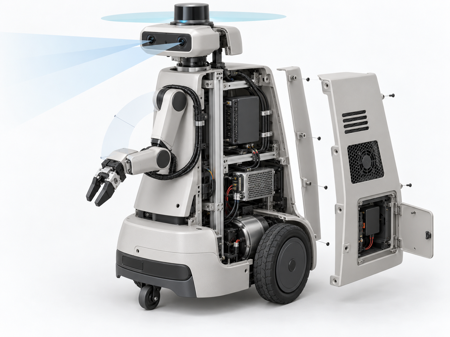
For outdoor or long-term operating scenarios, weather resistance, impact resistance, water ingress risk, and surface durability should also be verified according to the actual environment. The material name itself cannot replace test results; ultimately, the results of actual-robot assembly, full-range operation, and operating-environment verification should determine whether to proceed with small-batch custom robot enclosure fabrication.
How to manage part segmentation, tooling, and consistency in small-batch custom robot enclosure fabrication
When moving from a single prototype to small-batch production, the focus of custom robot enclosure fabrication shifts from “whether the shape can be produced” to “whether the enclosure can be assembled consistently, delivered repeatedly, and serviced conveniently.” When the design is still undergoing frequent changes, part segmentation and screw connections that facilitate modification and disassembly should be retained. When the structure is basically stable but the quantity is limited, CNC machining, 3D printing, vacuum casting, or a combined process can be evaluated. Only when the interface, appearance, and material requirements are relatively well defined is it appropriate to further assess whether injection molding and tooling investment are reasonable.
Part segmentation and consistency control in custom robot enclosure fabrication
Large enclosures do not necessarily need to be manufactured as a single piece. Proper part segmentation can improve fixturing, transportation, and maintenance, while also allowing exterior covers, mounting plates, and internal brackets to use more suitable processes. However, parting lines affect visual continuity, and datum transfer may cause accumulated deviations in hole positions and assembly surfaces. The following should be confirmed in advance for the project:
- Whether parting lines avoid the main visible surfaces, sensor windows, and areas subject to frequent impact;
- Whether screws, clips, and inserts can be reused, and whether tools can access them;
- Whether inspection fixtures, sample-part comparisons, or dimensional records for critical interfaces are required;
- How can color, texture, and coating be confirmed across different batches, and can replacement parts be matched to the original components?
A typical project scenario is as follows: a mobile service robot needs to have its top cover removed for battery maintenance while clearing the cameras and wheel assemblies. In this situation, the top cover’s seam alignment, locating pins, fastener sequence, and wiring-harness slack should all be verified before low-volume production. The final process still depends on the degree to which the design has been frozen, the production stage and quantity, dimensions, surface requirements, and shipping method; it cannot be judged solely by unit price or appearance.
What information is needed to request a quote for custom robot enclosure manufacturing?
For quoting custom robot enclosure manufacturing, the key information is not merely an appearance rendering, but engineering data that clearly describes the application scenario, interfaces, motion, and acceptance requirements. The closer the information is to the actual assembly condition, the more easily the manufacturer can assess part division, datums, materials, and processes.
Information checklist for custom robot enclosure manufacturing
- Overall dimensions and weight of the robot, as well as the locations of the chassis, joints, wheel assemblies, and internal mounting points.
- 3D exterior data, 2D interface drawings, or internal structure diagrams; clearly identify the hole locations, datums, and assembly surfaces that must be maintained.
- Locations and cutout requirements for cameras, radar, displays, microphones, speakers, emergency-stop buttons, charging ports, and other components.
- The operating ranges of the joints and wheel assemblies, the full-travel envelope, wiring-harness routing, bending allowance, and areas where collisions may occur.
- Ventilation openings, air ducts, maintenance hatches, fasteners, and disassembly directions; specify which components require frequent replacement or servicing.
- The operating environment, expected quantity, and project stage, such as an appearance mockup, functional prototype, low-volume trial production, or repeat production.
- Acceptable parting lines, colors, textures, surface treatments, and methods for determining acceptable appearance defects.
- Key acceptance criteria, including assembly clearances, sensor fields of view, motion interference, hatch operation, wiring-harness protection, and surface consistency.
If complete 3D data is not yet available, you can initially provide photographs of the physical unit, key dimensions, the robot’s intended use, an internal interface diagram, and the components that need to be cleared. However, these materials are generally suitable only for a preliminary assessment. Final manufacturability must still be confirmed in conjunction with the 3D data, datums, tolerances, materials, and specific process. A complex enclosure does not necessarily need to be manufactured as a single piece; exterior covers, mounting plates, transparent windows, and internal brackets may need to be designed separately.
Freeze the interfaces first, then determine the robot enclosure process
In practice, it is recommended to first freeze the use scenario, mounting points, operating range, and sensor locations, and then have the manufacturer evaluate part division, materials, processes, and the verification plan. Do not determine the manufacturing route based solely on a single rendering; once the appearance conflicts with disassembly, heat dissipation, or the motion envelope, subsequent rework often propagates from the enclosure design to the internal structure.
Frequently asked questions about custom robot enclosure manufacturing
Custom robot enclosure manufacturing cannot be assessed solely from an appearance drawing. The selection of materials, part division, interfaces, and processes generally needs to be determined based on the application scenario, internal structure, production stage and quantity, and results from testing on the actual machine.
Should the entire robot enclosure be made using the same process?
Usually, no. Exterior covers, precision mounting plates, sensor windows, internal brackets, and maintenance hatches serve different functions, so they may be produced separately using 3D printing, CNC machining, sheet metal fabrication, or other forming methods. The final choice depends on the dimensions, interface accuracy, weight, quantity, and surface requirements.
Why should physical assembly be validated first during the prototyping stage instead of relying solely on appearance?
An appearance model cannot fully reveal issues such as joint interference, obstructed sensor fields of view, cable harness bending, inaccessible access panels, or covered cooling vents. Prototypes for custom robot enclosure machining should be installed on the actual machine as early as possible to check full-range movement, disassembly and assembly sequences, and critical interfaces.
When should vacuum casting or injection molding be considered?
When the appearance and structure are relatively stable and a small number of copies are needed, vacuum casting may be considered. When the design is frozen, repeated molding is required, and appearance consistency is important, injection molding can then be evaluated. Both depend on the production quantity, parting-line and draft design, material requirements, and whether the tooling investment is reasonable.
What information should be provided first for custom robot enclosure machining when complete 3D data is unavailable?
You can initially provide overall photos of the robot, key external dimensions, internal mounting points, the range of motion of joints or wheel assemblies, sensor locations, hole and opening requirements, the operating environment, estimated quantity, and surface finish requirements. The manufacturer still needs to combine this information with subsequent 3D data, datums, tolerances, and process details to confirm manufacturability; a solution cannot be determined based solely on a single rendering.
Key takeaways
- For custom robot enclosure manufacturing, first confirm the use scenario, motion envelope, internal interfaces, and maintenance method before deciding on the material and process.
- An enclosure typically needs to be divided into cover panels, mounting structures, sensor windows, access doors, cable-routing channels, and joint-clearance areas.
- 3D printing is suitable for rapid design iterations, CNC machining for dimensional stability and precision interfaces, and sheet metal fabrication for panels and brackets. Molding or injection molding should be evaluated based on production volume and the degree to which the design has been finalized.
- Prototype validation should cover full-range motion, sensor fields of view, assembly sequence, cable routing, heat dissipation, collisions, and surface quality.
- When requesting a quotation, prepare the robot’s overall dimensions, 3D or 2D data, mounting points, range of motion, sensor locations, production quantity and phase, and operating environment.



