Why dexterous hand parts machining is harder than ordinary precision parts
Classify parts first, then choose processes: finger joints, metacarpal bases, and sensor housings
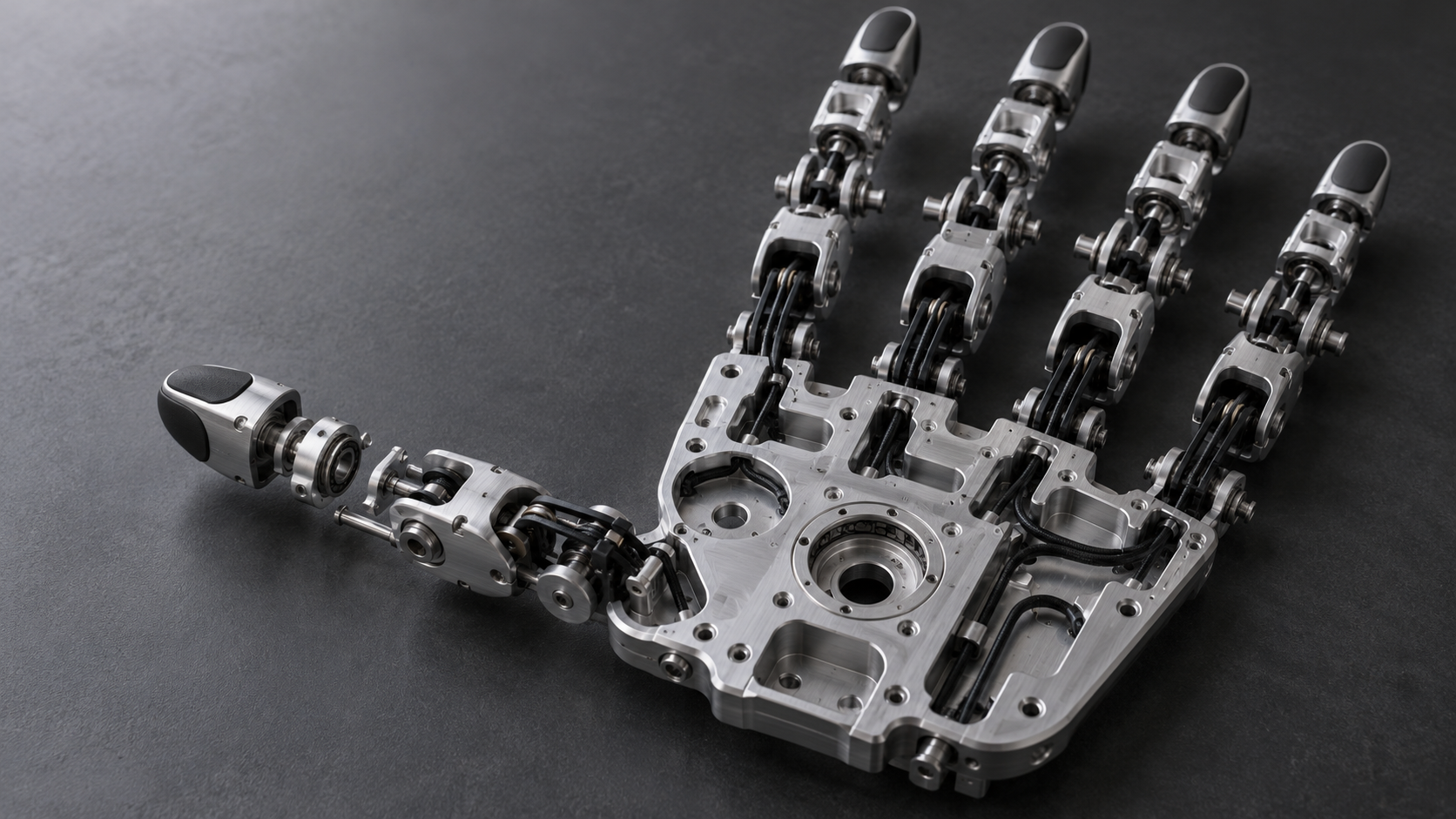
The most common mistake in dexterous hand parts machining is treating the entire hand as one part when defining the process. In reality, within the same hand, the working modes of the components differ greatly: some bear loads, some only guide, and some only cover. Classifying them first, then judging one by one whether to use CNC, 3D printing, sheet metal, or silicone casting, makes the judgment much clearer. The common industry practice is: load-bearing and mating surfaces use CNC, non-load-bearing and external form parts use additive manufacturing or silicone casting, and mixing processes within the same design is not unusual.
Finger joints: load-bearing, with mating surfaces, coaxiality matters
Finger joints are where the structural density is highest in the entire hand. They must simultaneously handle the revolute joint, routing channel, tendon sheath hole, and sensor mounting position. The key dimensions here are the coaxiality of the bearing hole or pin hole, the fit clearance of the revolute joint, and whether the joint wall thickness is rigid enough. Such parts usually use CNC milling or turning because they require dimensional consistency and repeatable mating surfaces. In terms of materials, aluminum alloy is light but has average rigidity, stainless steel is rigid enough but heavy, and engineering plastics such as POM and PEEK are also common in lightly loaded joints. Which one to choose depends on the load and weight budget, and the fit tolerances on the drawing will directly determine machining difficulty.
Metacarpal bases and sensor housings: the trade-off between datum surfaces and thin walls
The metacarpal base is the mounting datum for the entire palm. It usually has multiple hole positions and one large mounting plane, and the key points are flatness and hole position tolerance. It is well suited to CNC machining because the datum surface can establish the hole relationships in a single setup. The sensor housing is another matter: it is often thin-walled, has shielding or sealing requirements, is prone to deformation during machining, and the sealing surface also requires surface roughness. Such parts do not necessarily have to be CNC machined. For thin-walled housings, using 3D printing for prototypes and then considering subsequent processes is a common transitional approach. The outer fingertip pads and tendon sheaths are non-load-bearing parts, where elasticity and friction are the main indicators, and they basically do not follow the CNC route.
After classifying the parts, a practical order of judgment is: first check whether the part bears load, then check whether it has mating surfaces and datum requirements, and finally check wall thickness and batch size. If these three differ, the process conclusion may differ. Insisting that the entire hand use a single process is often neither economical nor capable of achieving the required precision. The following sections expand, in this order, on the process and DFM judgment for each type of part.
The place of CNC machining in dexterous hand components: load-bearing parts and mating surfaces
Which dexterous hand components should use CNC: joints, bases, and sensor mounting surfaces
Material selection: the trade-offs among aluminum alloy, stainless steel, POM, and PEEK
How to control the deformation risk in thin-wall turning and milling
3D printing and vacuum casting: outer covers, tendon sheaths, and early validation
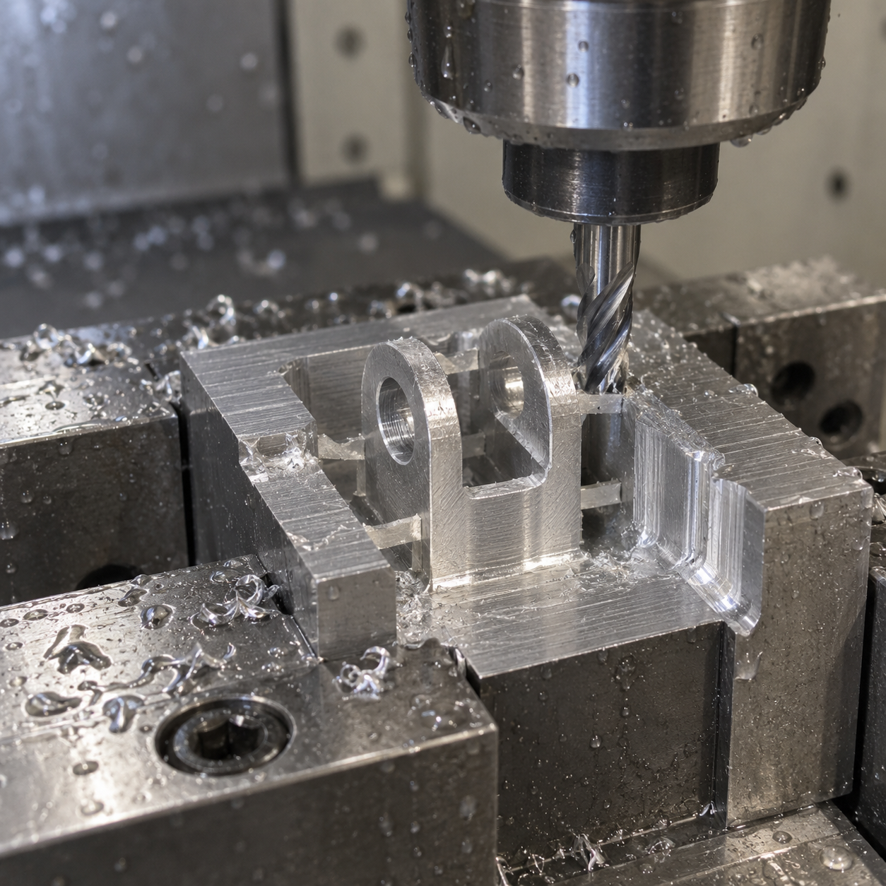
In the machining of dexterous hand components, it is already fairly clear that load-bearing parts and mating surfaces should be handed to CNC; what truly makes it easy to take the wrong path are instead non-load-bearing parts such as outer fingertip pads, tendon sheath conduits, and cable routing brackets. Structurally they are often more complex—fingertip pads need texture and friction features, tendon sheaths need to run through curved channels, and brackets need to fit the inner cavity of the entire hand—but they carry little force and have short dimension chains, so forcing them out with CNC is costly and slow to modify. Such parts are suitable for additive manufacturing or vacuum casting, provided that it is first made clear which surfaces must be post-machined.
Applicable boundaries of additive manufacturing: what problems SLA, MJF, and SLS each solve
SLA is suitable for parts such as outer fingertip pads that require surface quality and detail. Photopolymer resin can produce relatively fine textures, and after subsequent sanding and blasting the feel approaches the target, making it quick to produce several sets of trial-fit parts. The limitation is that it is brittle and poor in impact resistance, and long-term repeated grasping can easily cause cracking at the root of thin walls, so it is more suitable for assembly and feel validation, not as a final production material.
MJF and SLS use nylon systems, which have good toughness and can make snap fits and elastic structures. Tendon sheath conduits, cable routing brackets, and palm internal skeletons are relatively easy to make with these processes. There is no obvious cliff in strength along the layer grain direction, but the anisotropy of nylon still remains—interlayer bonding along the stacking direction is weaker than within the layer, and thin-walled parts fail first when loaded perpendicular to the layer direction. For fine structures that bend repeatedly, such as hinges and snap fits, the force direction must be considered when arranging the print layout.
Regardless of the additive method, machining allowance must be left on mating surfaces. The dimensional consistency of printed parts is affected by thermal shrinkage, powder removal, and post-curing, and is not on the same order as CNC. For locations with fit requirements such as bearing seats, pin holes, and sealing surfaces, the common industry practice is to print with allowance and then finish machine, or simply split that location into an independent CNC part and assemble it with locating features.
Vacuum casting transition: the cost-effectiveness range for small-batch outer covers
If the outer fingertip cover passes validation and requires dozens of assembled units, continuing with SLA printing makes the per-part cost too high, and the material properties may not be right either. At this point, handboard duplication (vacuum casting) is a common transitional method: use printing or CNC to make a prototype master model, make a silicone mold, and then cast polyurethane. Polyurethane offers a wide range of hardness options and can be tuned to approach the target fingertip's Shore hardness and friction characteristics, and it withstands repeated gripping better than photosensitive resin.
The boundaries of duplication are also clear. Silicone molds have a limited lifespan and commonly begin to wear after a few dozen parts, with dimensions and surfaces gradually drifting; beyond that quantity, the unit price advantage disappears and injection molding should be considered. Duplicated parts also shrink, so after casting the mold dimensions need to be corrected according to the material grade. Sink marks easily form at the junction of thin and thick walls, and these must be marked in the DFM before making the silicone mold.
How to choose between printing, duplication, and injection molding: a trade-off framework
- Validation stage, structure still subject to change: direct 3D printing. A revised drawing can be reprinted the same day, at the cost of only approximating material and surface.
- Small batch, material properties need to be close to the final part: vacuum casting. Make the master model once, then produce several silicone molds, suitable for assembly validation within a few dozen parts.
- Structure frozen, stable batch: switch to injection molding. But draft angle, wall thickness uniformity, and gate location must all be completed in this round of DFM, otherwise mold modification costs will far exceed the first two processes.
The order of judgment is not "which process is better," but "what stage is this part at now, and will it change in the next step." The characteristic of dexterous hand accessory machining is frequent iteration. Outer covers and tendon sheaths are often printed for validation first, and only after the structure stabilizes is duplication or injection molding discussed. 3D printing capabilities and rapid prototyping cover exactly this rapid iteration phase, while injection molding capabilities connect to the mass production phase after the structure is frozen.
One final reminder: whether a printed part can be directly assembled depends on what function it serves. If it is only an outer cover or cable routing guide, a printed part is entirely sufficient; once it involves load bearing, sealing, or repeated fatigue, material properties and process defects must be factored in, or the critical areas should be changed to CNC parts. This judgment must be made during the drawing review stage, not after assembly reveals a cracked fingertip and you have to go back and revise.
Tolerances and inspection: how to allocate the tolerance budget in dexterous hand accessory machining
The most problematic link in dexterous hand accessory machining is not that a single dimension cannot be achieved, but that tolerances are not layered. With dozens of dimensions on one hand, if the assembly technician collects them on the basis of "if the drawing has a tolerance, make it to the tightest," costs will spiral out of control, lead times will be eroded, and in the end it may still not assemble smoothly. The approach to tolerance budgeting is: first distinguish which dimensions are mating dimensions, which are mounting datums, and which are free surfaces, then decide where to invest money and inspection labor.
Mating dimensions, mounting datums, and free surfaces: the allocation logic for three types of dimensions
Mating dimensions carry motion or positioning functions, such as bearing seats, pin holes, and gear meshing center distances. The tolerances of these dimensions directly determine joint clearance and backlash. The common industry practice is to select shaft-hole fits from clearance fit bands such as H7/h6, then fine-tune according to feel requirements; the specific grade chosen must be back-calculated from the clearance requirement after assembly, not copied. Mounting datums are the mating surfaces between the metacarpal base and the phalanges, and the position tolerance of locating pin holes; they determine the cumulative assembly error of the entire hand. Free surfaces include outer cover contours and the inner walls of cable routing grooves, and generally can be collected at general tolerances.
A practical allocation order is: first lock the position tolerance of the assembly datums, then allocate mating dimensions, and only finally tighten free surfaces. The reverse order will cause the tolerances of the first two categories to be squeezed by free surfaces, and they will fail to match during assembly.
Coaxiality, rotational clearance, and mounting surface flatness: how to set several typical dimensions
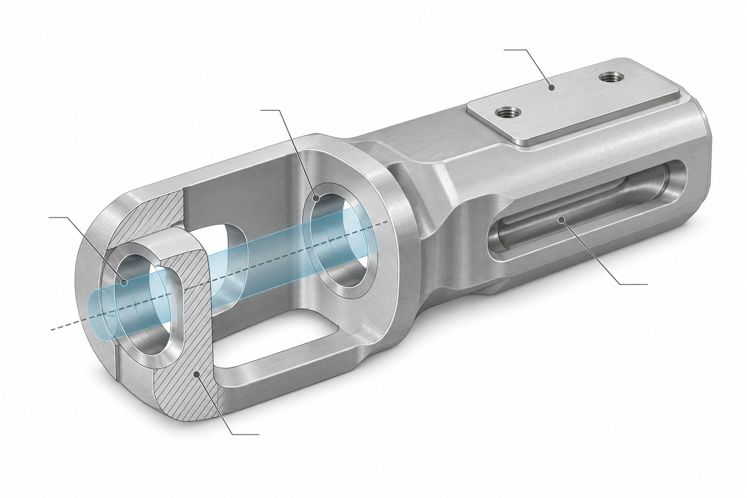
Bearing seat coaxiality is the most precision-demanding item in dexterous hand accessory machining. If the two bearing bores are not coaxial, rotation will have periodic sticking, and tendon tension will fluctuate accordingly. A common practice is to control coaxiality at the 0.01–0.02 mm level as a reference, but this depends on bearing grade and joint diameter; larger diameters usually allow wider values. The final value must be confirmed according to the drawing and actual assembly measurements. Joint rotational clearance is not better the smaller it is—too tight will cause motor stall and heating, while too loose will cause backlash. Generally a fit allowance of 0.02–0.05 mm is left, and the specific value is calibrated by prototype feel.
The flatness of sensor mounting surfaces is easily overlooked. If a force sensor is mounted on a warped surface, the zero point will drift and calibration will be wasted. Such surfaces usually require flatness within 0.02–0.05 mm, and must be dimensioned in association with the assembly datum, rather than simply giving a standalone flatness frame.
Cost-driven tolerances: not all dimensions are worth tightening
Each time a tolerance is tightened by one grade, the cost and scrap rate of CNC machining jump. Tightening the tolerance of a non-mating surface from ±0.1 mm to ±0.02 mm provides almost no functional benefit, yet requires more inspection labor and may be judged scrap due to being out of tolerance. The criterion is simple: will this dimension being out of tolerance affect assembly or motion? If yes, tighten it; if no, leave it at general tolerance.
Hole positions in cable routing channels fall in the middle ground. If a hole position is slightly off, it is enough that the cable can be inserted during assembly, but if it is too far off, the cable will be squeezed at the joint bend and may eventually wear through the insulation. Giving such dimensions a medium tolerance band (such as ±0.05 mm) is usually sufficient, and full CMM inspection is not necessary.
How inspection should match tolerances: datum consistency matters more than equipment precision
Using a CMM to measure mating dimensions and position tolerances for first article inspection is common practice; 3D scanning is better suited for checking overall contours and the deviation distribution of free surfaces, especially outer covers and complex curved surfaces. The two are not substitutes for each other. The key is that the inspection datum must be consistent with the assembly datum. If the drawing specifies an A-B combined datum, but inspection is set up only on surface A, the measured position tolerance will not match actual assembly, and a first article that passes may still fail to assemble.
The focus of batch sampling inspection should be on mating dimensions and datum position tolerances, while free surfaces can be quickly compared by scanning. It is best to clearly state the datum scheme in the inspection report to facilitate alignment with the assembly side. For specific capabilities regarding scanning and reverse inspection, refer to 3D scanning capabilities.
- Lock datums first: prioritize allocating the position tolerance of mounting datums, then address mating dimensions.
- Set mating dimensions by function: coaxiality, rotational clearance, and flatness each correspond to motion or sensing requirements; do not apply a one-size-fits-all approach.
- Relax non-critical surfaces: Apply general tolerances to non-mating surfaces and invest the savings in critical dimensions.
- Align inspection datums: The datum scheme for CMM or scanning must match the assembly datum, otherwise the data is meaningless.
Fixturing and routing channels: two easily overlooked machining details
Most dimensional problems in dexterous hand component machining don't stem from machine accuracy, but from two things: the fixture deforms the part, or the routing channels lack sufficient positional accuracy and the hole edges aren't cleaned up properly. The former only shows up after the fixture is removed; the latter only shows up when the last tendon is installed. These two aspects are usually invisible on a quote sheet, yet they determine whether the assembly line runs smoothly.
Fixturing deformation in thin-walled and slender joints
Finger joint walls are often on the order of 1–2 mm thick, and outer covers are even thinner. When held directly in a three-jaw chuck or flat-jaw vise, the clamping force is enough to turn a round hole into an ellipse; after release the dimensions spring back, but the surface already bears pressure marks, and the mating surface accuracy can't be recovered. There are three common countermeasures in the industry:
- Process tabs — leave a patch of material on a non-functional surface specifically for clamping, then mill it away after finishing the mating surfaces.
- Vacuum fixturing or custom soft jaws — spread the clamping force over a larger area to avoid localized crushing.
- Split-sequence machining — after roughing, leave stock and release the clamp to let stresses relieve, then finish the critical mating surfaces.
There's a very simple way to judge whether a fixturing setup is sound: after finishing the critical dimensions, remove the fixture and re-measure. If the dimensions shift by more than a fraction of the tolerance band, the clamping force participated in forming the part, and batch consistency for that lot is at risk. This re-measurement is especially important for thin-walled parts — don't rely only on in-process measurement values.
Positional accuracy of routing channels and tendon-sheath holes
Tendon-sheath holes, routing grooves, and sensor pass-through holes — each dimension individually falls within normal tolerances, but their relative positions determine whether the tendon routing runs smoothly. When adjacent hole positions deviate too much, the tendon forms a kink at the hole edge, friction concentrates, and service life drops noticeably. On the assembly line this shows up as "it goes together, but the feel is gritty," and it's very hard to trace back to a specific dimension.
Hole-edge treatment is the other side of the same issue. Incomplete deburring or uneven fillet radii turn into cutting edges when the tendon reciprocates repeatedly. In engineering practice, hole edges are usually required to have at least a fillet or chamfer, with the specific radius determined by tendon diameter and material. Specifying "no burrs at hole edges, sharp edges blunted" on the drawing is more effective than just calling out a diameter. On the machining side, such requirements often need dedicated deburring tools or manual operations, and it's worth stating this upfront when quoting.
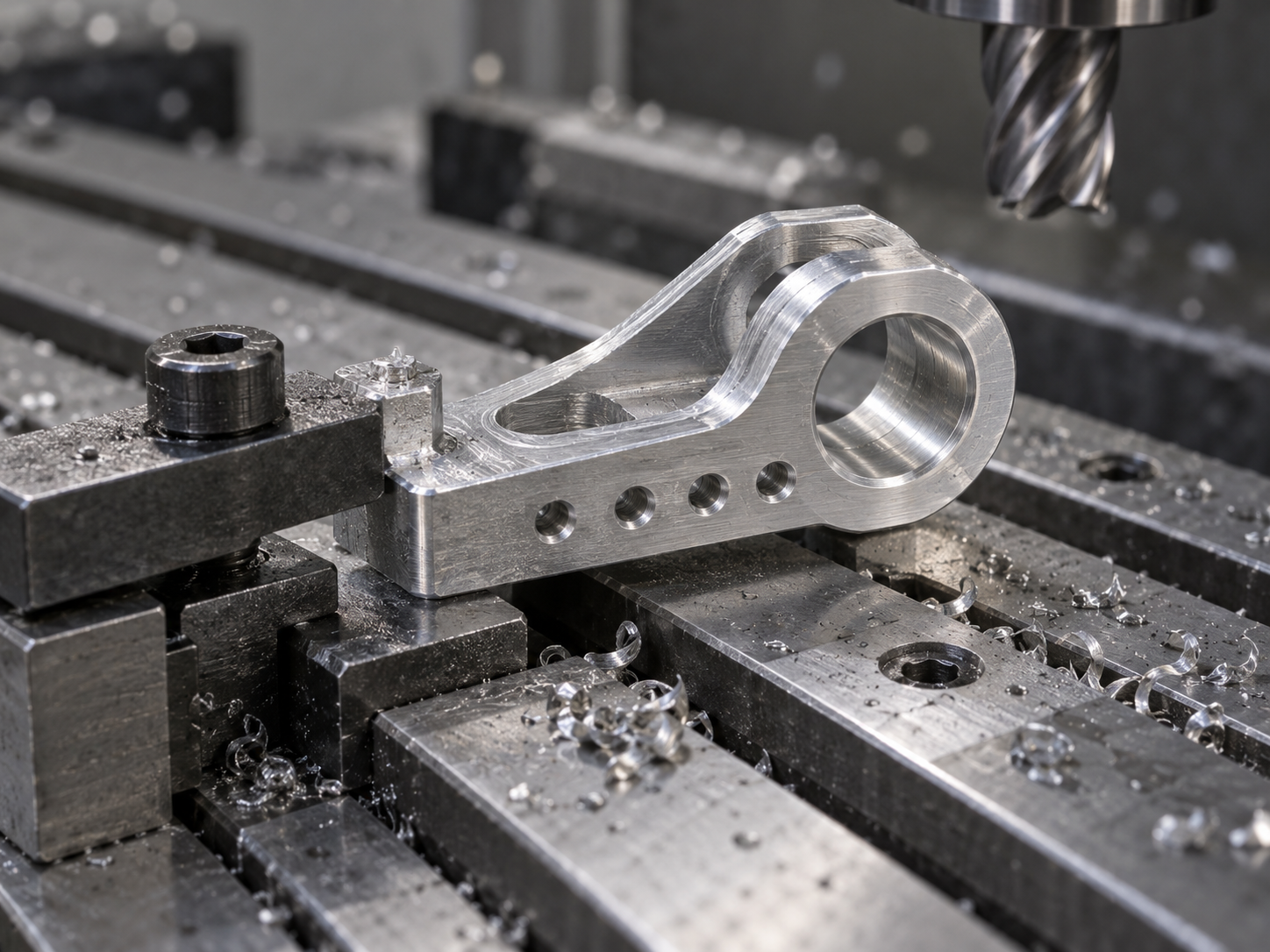
These two types of details should typically be settled during the DFM review stage. If the positional accuracy requirements for routing channels genuinely affect assembly, you can directly specify position tolerances for the relevant hole groups on the drawing rather than individual linear dimensions; for the fixturing scheme, you can confirm with the machining vendor whether process tabs are needed and whether removing them will affect cosmetic surfaces. Communicating these upfront is far more cost-effective than fixing things by hand after the fact.
From prototype to small batch: the production transition for dexterous hand component machining
When a dexterous hand goes from engineering prototype to a small batch of dozens or hundreds of units, the question most often asked is: When should we switch from CNC to injection molding? There's no universal answer, but there is a decision chain: first look at annual volume, then at the structural complexity of the individual part, and finally at whether the material allows a switch. The production transition for dexterous hand component machining is essentially about turning "we can assemble it" into "we can assemble it every batch."
For load-bearing parts like finger joints and metacarpal bases, the common industry practice is to keep them on CNC milling or turning long-term. The reason isn't unit cost but iteration speed: to change a bearing bore diameter or add a routing groove, with CNC you just modify the program and re-fixture, whereas injection molding requires a mold change. Typically, only when a plastic part's annual volume stabilizes at several hundred to several thousand units and the structure is no longer undergoing major changes does it become worth seriously evaluating injection molding. This threshold is strongly correlated with part volume, mold cavitation, and surface requirements — it depends on the specific drawing and mold scheme, so don't force-fit a single number.
Which dexterous hand components should stay on CNC and which should switch to injection molding
A rough division: load-bearing parts with mating surfaces that need post-machining to guarantee hole positions tend to stay on CNC; non-load-bearing, thin-walled outer covers whose shape is dominated by curved surfaces tend to switch to injection molding. Sensor housings sit in the middle — if the sealing surfaces and mounting hole positions are demanding, the housing itself may still use CNC, with only the decorative outer cover switched to injection molding. If the metacarpal base is a single multi-hole plate, CNC's flatness and hole-spacing consistency are usually more controllable; once it becomes a thin shell with snap fits, injection molding's advantages emerge.
Note a common misjudgment in dexterous hand component machining: treating "complex shape" as "must be injection molded." Complex doesn't equal suitable for injection molding. What makes injection molding truly cost-effective is sufficiently large batch size, a structure that allows demolding, and a material that can be injection molded. If any one of the three is missing, CNC or vacuum casting is actually less trouble.
DFM upfront: write draft angles, wall thickness, and shrinkage compensation into the drawing
For parts being converted to injection molding, DFM cannot wait until just before tooling—it's best to get it into the drawings before the part design is frozen. Three parameters are most critical:
These three all fall into the category of "not written on the drawing, but costing a fortune after tooling." Before evaluating injection molding, it's advisable to have the supplier do a round of DFM feedback to clarify draft, wall thickness, and gate location all at once, rather than changing after tooling. If you're unsure about material shrinkage and structural feasibility, first use 3D printing or vacuum casting to make a few pieces for actual fit testing—that's more reliable than going straight to a steel mold.
The effect of gate location on the filling of thin-walled dexterous hand components
Dexterous hand outer covers and fingertip sheaths are often thin and long, and gate location directly determines whether they can fill completely. Opening the gate in a thick area and letting the melt advance toward the thin end makes it easier to fill than the reverse; multi-point gates can shorten the flow path but leave weld lines, which are troublesome if they land on load-bearing or sealing surfaces. Common failures in thin-walled parts are short shots at the end, insufficient weld line strength, and warpage—many of these three can be predicted before tooling using mold flow analysis, and it's worth the time.
The trade-off between cost and iteration speed can be viewed this way: CNC has a higher per-part cost, but design changes incur almost zero tooling cost; injection molding has a lower per-part cost, but the mold investment is one-time and mold changes take a long time. For products like dexterous hands that are still iterating rapidly, a common approach is to route load-bearing parts and outer covers differently—keep joints on CNC, switch sheaths to injection molding, and let each use its own optimal solution rather than forcing a single process for the whole hand. To evaluate which route a specific part should take, you can first use AI chat quote or classic quote to put the costs of both CNC and injection molding side by side, then decide.
FAQ: Process and DFM follow-up questions for dexterous hand component machining
The following questions are basically the ones most frequently asked during drawing review and prototyping communication. The answers give the direction for judgment; specific values should still be based on drawing annotations and actual assembly requirements.
For load-bearing parts like dexterous hand finger joints, how is the material generally selected?
Look at the load path and mating method, not the grade first. Aluminum alloys (such as 6061, 7075) are often used for joint bodies that need to be lightweight yet rigid, with obvious weight-saving benefits, but wear surfaces usually need bushings or hardening treatment; stainless steel offers better strength and wear resistance at the cost of increased weight and machining difficulty; engineering plastics like POM and PEEK are suitable for low-load rotating parts or insulating spacers, with PEEK offering better heat resistance and dimensional stability, but at higher material cost and faster tool wear. The common industry approach is to use metal for the load-bearing body and pair plastic or bushings for the friction pair. Final material selection should be confirmed together with load, lubrication method, and assembly tolerances—judging by material grade alone easily leads to misjudgment.
How much tolerance should be given for joint bearing seats and sensor mounting surfaces?
First distinguish the dimension type before assigning tolerance. For mating dimensions such as bearing seats and pin holes, the industry commonly receives around IT7 or even tighter, with coaxiality and position tolerance annotated according to the assembly datum; sensor mounting surfaces care more about flatness and fit clearance, and don't necessarily need extreme dimensional tolerances; free surfaces and cosmetic surfaces can be loosened. The key is not to mark the entire drawing with tight tolerances—cost rises rapidly as tolerances tighten, and many dimensions have no effect on function. It's advisable to mark the datum system and key mating dimensions on the drawing, and treat the rest as general tolerances, so the machinist can focus effort where it truly affects assembly.
Can 3D-printed dexterous hand components be installed directly?
It depends on the location. Non-load-bearing parts such as outer fingertip covers, tendon sheath guides, and cable routing brackets can usually be used directly after SLA or MJF printing, support removal, and sanding; but for locations involving mating surfaces, bearing seats, and sealing surfaces, the layer lines and anisotropy of printed parts affect dimensional stability and wear resistance, so generally allowance must be left for post-machining, or simply switch to CNC. In addition, printed parts tend to have burrs and steps at hole openings and thin-wall edges, so before assembly confirm whether fillets and deburring are in place. Whether it can be installed directly depends on whether that surface participates in precision mating, not on the printing process itself.
How can you tell whether a fixturing plan will cause part deformation?
The most direct judgment is to measure once after removing the fixture. If key dimensions spring back out of tolerance after releasing the jaws, the clamping force or support method has a problem. This is especially obvious for thin-walled parts and slender joints; the common industry approach is to add process bosses, switch to vacuum chucking or soft jaws, and remove material symmetrically in separate operations to distribute cutting force and clamping force. Another signal is large dispersion between first-article and sampling data—with the same program and same batch of material, large dimensional variation is often not a tool problem but unstable repeat positioning in fixturing. During review, you can directly ask the machinist: how is the datum surface set, where are the clamping points, and how is re-inspection done after unclamping.
When should dexterous hand components switch from CNC to injection molding?
Mainly depends on batch size, iteration status, and structural complexity. When the structure is still changing and the batch is only a few dozen pieces, CNC or vacuum casting is more cost-effective, since drawing changes don't require mold changes; when the structure is frozen and annual usage reaches several thousand pieces or more, the per-part cost advantage of injection molding becomes obvious. Before switching to injection molding, draft angle, wall thickness uniformity, shrinkage compensation, and gate location must be put into DFM in advance, and thin-walled parts especially need filling and warpage risks confirmed. Not all parts are suitable for switching either—load-bearing joints and precision mating surfaces often remain CNC or use inserts. There is no universal number for the switching point; it's advisable to calculate based on current batch size and expected number of iterations before deciding.
Key takeaways
- The core contradiction in dexterous hand parts machining is the superposition of thin-walled rigid parts and high-density routing channels. Process selection starts with part function, then looks at the tolerance budget.
- For load-bearing parts such as finger joints and metacarpal bases, the common industry practice is to use CNC to ensure mating surfaces; outer finger pads and tendon sheaths can use 3D printing or silicone casting as a transition to low-volume production.
- Tolerances are not better the tighter they are. Flatness, coaxiality, and position should be allocated according to the assembly chain, and general tolerances can be given for the remaining surfaces, avoiding cost being eaten up by irrelevant dimensions.
- The fixturing plan often affects the result more than machine tool selection. Thin-walled parts require process bosses or vacuum clamping, and the inspection datum must be consistent with the assembly datum.
- When moving from low-volume to mass production, draft, wall thickness, and shrinkage compensation for injection molding must be brought into DFM in advance; otherwise, the cost of changing the mold once far exceeds the extra design time spent upfront.



