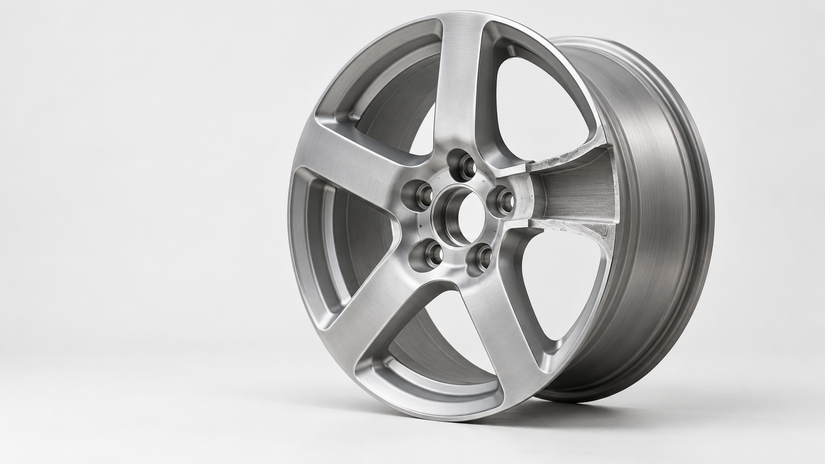
What 6061-T6 Forged Wheels Each Represent: Alloy, Forging, and Heat Treatment Condition
Is the marking “6061-T6 forged wheel” on a drawing sufficient to prove that this forged aluminum alloy wheel can pass durability testing? No. These designations answer three separate questions: 6061 indicates the type of aluminum alloy used, forged indicates the plastic forming process applied to the billet, and T6 indicates that the material is in a specific heat treatment condition. They do not constitute proof that the complete wheel meets performance requirements.
What the 6061 Alloy Designation Indicates
6061 is a heat-treatable Al-Mg-Si alloy that typically provides a good balance of strength, corrosion resistance, and machinability. However, the designation cannot replace material certification. Engineering reviews should verify the alloy standard, supply condition, heat lot number, and whether the actual billet matches the drawing and purchasing specification. Different cross-sections, degrees of deformation, and treatment batches may also affect final performance.
T6 Is Not a Forging Grade
T6 generally refers to a heat treatment condition achieved through solution treatment, quenching, and artificial aging. It does not indicate forging quality or correspond to a single standardized strength value. The supplier should provide heat treatment furnace batch and process records, together with hardness testing, necessary mechanical property verification, and remeasurement of critical dimensions, to demonstrate that the condition is properly controlled. Forging improves material density and grain-flow characteristics, but insufficient die filling, laps, cracks, local thinning, or excessive subsequent machining may still weaken overall wheel performance.
Therefore, the lightweight design of a forged aluminum alloy wheel cannot be evaluated solely from the material label. Spoke cross-sections, rim wall thickness, mounting-face stiffness, dynamic balance, impact loads, and fatigue loads should all be included as design inputs. The final conclusion must be based on the inspection and durability results obtained against the drawings, the target vehicle load spectrum, applicable standards, or customer specifications.
From Billet to Forged Blank: What Risks Must Be Controlled During Forming of a Forged Aluminum Alloy Wheel
Forming a forged aluminum alloy wheel is not simply a matter of pressing a piece of aluminum into a rim. The material must fill the rim, spokes, and connecting transition areas along a controlled deformation path and within a controlled temperature range. The process chain typically begins with qualified billet preparation, followed by preform preparation, die forging, trimming, and post-forging inspection before proceeding to subsequent heat treatment and CNC machining. This process differs from that for low-pressure cast wheels, so melting, refining, and cast-part X-ray inspection procedures should not be applied directly.
Billet and Preform: First Stabilize the Material Condition and Deformation Distribution
The billet’s alloy designation, supply condition, heat-lot traceability, and initial dimensions should be confirmed first. Temperature changes between heating, transfer, and die entry can affect material flowability and die filling. The volume distribution of the preform must not be judged by appearance alone: insufficient material at spoke branches, rim edges, or spoke–rim transitions may later result in incomplete filling, local thinning, or inadequate machining allowance.
Die Filling and Post-Forging Inspection: Containing Defect Risks at the Billet Stage
Higher forging pressure is not necessarily better. The key is whether the temperature window, die cavity, deformation distribution, and material flow are properly matched. Uncontrolled filling can cause folds, cracks, local overheating, or interrupted grain flow; even if these defects are concealed by subsequent turning, they may become fatigue-crack initiation points at spoke transitions. Excessive allowance increases the cutting volume, while uneven allowance can create risks involving wall thickness, runout, and dynamic balance.
During delivery review, require access to the forging process parameter records, first-article billet dimensions, and inspection results for critical sections, and select applicable nondestructive testing for forgings based on the defect type, structure, and customer specifications. The objective is not merely to prove that forging has been completed, but to demonstrate that the spokes, rim, and their transition areas have achieved a machinable, traceable billet condition suitable for subsequent durability validation.
How T6 Heat Treatment Affects the Strength, Hardness, and Deformation of Forged Wheels
The “T6” in 6061-T6 denotes the heat-treatment condition, not the forging grade. For aluminum-alloy forged wheels, heat treatment typically includes solution treatment, quenching, and artificial aging: solution treatment brings the alloying elements into solid solution, quenching preserves the supersaturated condition, and artificial aging then improves strength and hardness through precipitation hardening. The final result cannot be inferred from the grade suffix alone; it must also be evaluated together with the furnace lot, section location, and mechanical-property records.
Heat-Treatment Control Points for 6061-T6 Forged Wheels
6061 is relatively sensitive to the quenching process. Furnace-temperature uniformity, loading quantity, part spacing, support method, and the transfer time from furnace exit to quenching can all cause hardness variation within a batch or wheel deformation. If cooling is uneven, dimensional drift may occur in the mounting pad, rim, or spoke areas; if aging is insufficient or excessive, strength, hardness, and ductility may also deviate from project requirements.
What Quality Evidence Is Required for Heat Treatment of Forged Wheels
- Process records: Verify the heat-treatment lot, loading quantity, and part batch; confirm that the solution-treatment, quenching, and artificial-aging processes were controlled; and retain furnace-temperature curves, furnace-temperature uniformity records, or equipment calibration records.
- Condition verification: Check hardness in accordance with the drawing, material standard, or project specification and, where necessary, provide mechanical-property results such as tensile strength, yield strength, and elongation; the sampling location and specimen representativeness should be clearly defined.
- Deformation and remeasurement: After heat treatment, remeasure the mounting face, center bore, rim runout, critical wall thicknesses, and other affected dimensions, and record the reinspection results after the disposition of nonconformities, straightening, or rework.
Therefore, a supplier’s submission of a “6061-T6” label does not constitute proof that heat treatment has been completed. The furnace-lot records, hardness results, dimensional remeasurements, and applicable mechanical-property reports should be linked to the same batch of forged wheels; specific temperatures, soaking times, and acceptance criteria must be based on the material standard, wheel drawing, and project specifications.
CNC Machining of Forged Wheels: Datums, PCD Holes, Rim Runout, and Deburring
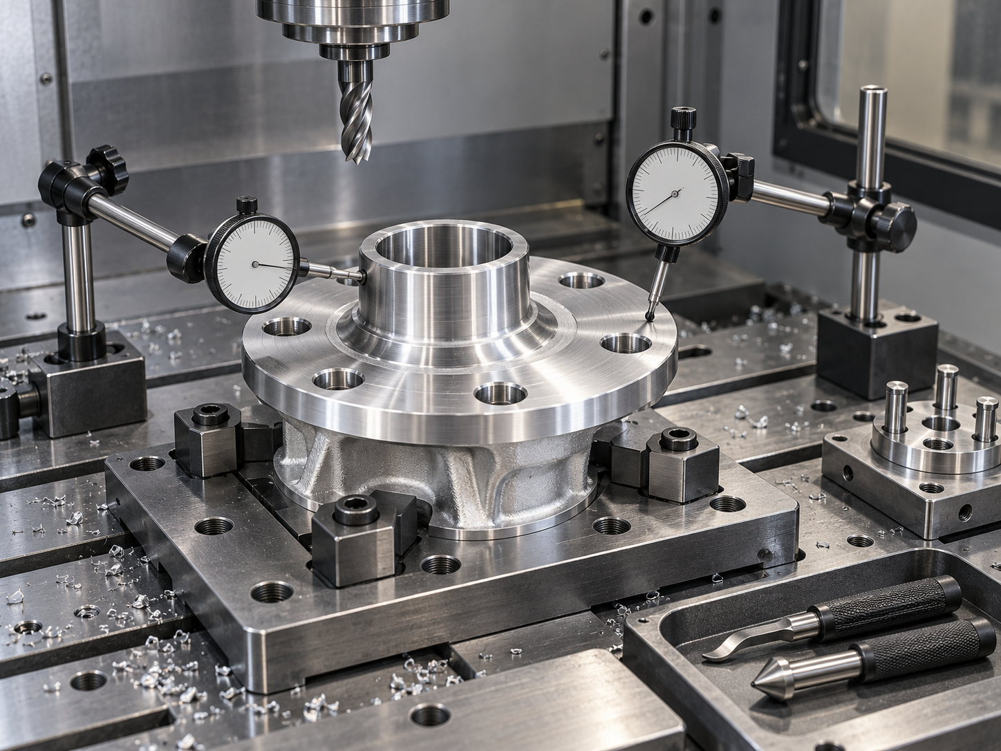
Once a forged wheel enters CNC machining, the objective is not simply to “machine it more accurately,” but to convert the forging datums consistently into the dimensional relationships among the mounting face, center bore, PCD bolt holes, and rim rotational surface. Typically, the rim and mounting pad are turned first, followed by machining of the center bore, PCD holes, and valve hole, then finish machining, deburring, cleaning, and remeasurement. The locating surfaces, clamping positions, and inspection datums used at each step should be clearly defined.
Forged-Wheel CNC Machining Datum Chain and Clamping Deformation
If the mounting pad is not located securely, using this surface as the datum for subsequently machining the center bore and PCD holes may cause hole-position deviation, end-face runout, or radial rim runout. Thin-walled rim and spoke areas may also undergo local deformation due to clamping force, cutting force, or uneven allowance. Tool wear can further affect hole diameter, end-face flatness, and surface roughness; therefore, the first article, the part after tool changes, and the final part of each batch should all be remeasured according to the drawing requirements.
- Turning: Check the mounting face, rim rotational surface, end-face runout, and allowance on critical wall thicknesses.
- Drilling and finish machining: Verify the center-bore diameter, PCD hole positions, hole diameters, hole-mouth condition, and valve-hole orientation.
- Deburring and cleaning: Pay particular attention to spoke–rim transitions, hole mouths, and rear-side steps to prevent assembly interference, coating residue, or local stress concentration.
Quality evidence should come from measurement records such as dimensional reports, dedicated gauges, or coordinate measuring machines, rather than simply stating “CNC ensures high precision.” Rim runout, mounting-face runout, PCD position, and critical wall thickness should be referenced to the same datum system. After cleaning, it should also be confirmed that there are no chips or residual fluid inside the holes, cavities, or spoke-to-rim transitions.
What Dimensional, Nondestructive, and Functional Inspections Are Required for a Forged Aluminum Wheel Hub
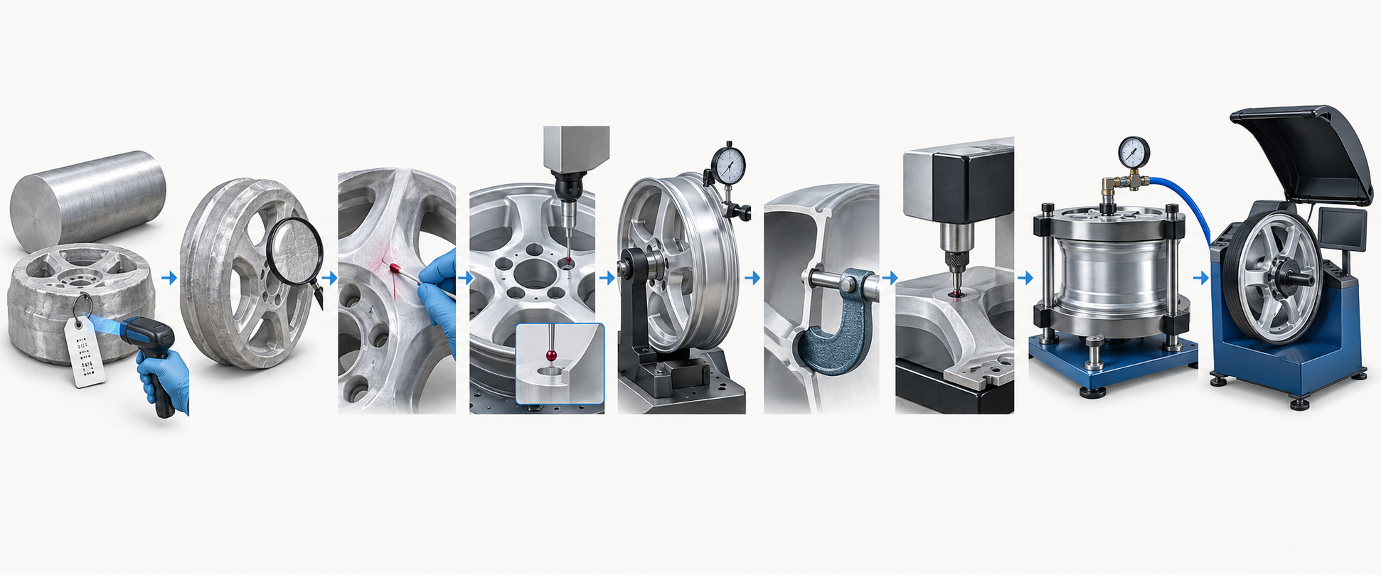
Inspection of a forged aluminum wheel hub cannot focus solely on appearance, nor can a “6061-T6” label replace comprehensive quality evidence for the entire wheel hub. The inspection sequence should establish traceability step by step across the material heat lot, forging, heat treatment, CNC machining, and finished-product functionality. Every inspection should answer three questions: where could failure occur, what method can detect it, and which record proves that it has been controlled?
| Inspection Stage | Primary Risks | Quality Evidence |
|---|---|---|
| Material and Forging | Heat-lot mix-up, laps, cracks, and surface defects | Material certificates, heat-lot traceability, visual inspection, and applicable nondestructive testing records |
| Dimensions and Machining | Mounting-face runout, PCD hole-position deviation, center-bore eccentricity, insufficient wall thickness, and burrs | Critical dimensional reports, gauge or measurement records, and rim circular runout and face runout results |
| Finished-Product Functionality | Air leakage, rotational imbalance, and assembly interference | Air-tightness inspection, dynamic-balance results, and final release records |
Nondestructive testing methods should be selected according to the forging structure, defect type, drawing requirements, and customer specifications. For forged wheel hubs, the focus is typically the continuity of the post-forging surface and internal structure. The X-ray process commonly used for low-pressure cast wheel hubs should not be treated as the standard answer for all forged wheel hubs. If risks exist at the spoke-to-rim transition, around holes, or in areas with changes in thickness, the inspection coverage and acceptance criteria should be clearly defined.
Dimensional and Functional Inspections for Forged Aluminum Wheel Hubs Cannot Substitute for Each Other
The mounting face, center bore, and PCD hole positions should be evaluated within the same datum chain, together with checks of rim runout, critical wall thickness, and valve-hole position. Passing visual inspection does not mean that air tightness is acceptable; passing static dimensional inspection does not mean that dynamic balance is acceptable during rotation. Hardness after heat treatment can only serve as one part of a condition check; it still needs to be combined with heat-lot records, dimensional remeasurement, and the applicable material standard or project specification.
From finite element hotspots to durability testing: How to validate a high-strength aluminum forged wheel hub
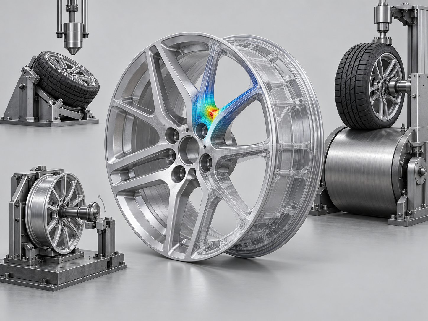
An aluminum forged wheel hub is not validated through a single static strength calculation. During vehicle operation, the hub simultaneously withstands braking and launch torque, lateral loads during cornering, and impact loads from uneven road surfaces. Validation should connect design loads, finite element hotspots, test programs, and failure criteria into a continuous chain of evidence.
First identify the finite element hotspots in the aluminum forged wheel hub
The finite element analysis should use the target vehicle's load spectrum, tire and mounting boundary conditions, material condition, and the actual wheel hub geometry, rather than simply applying the strength values for the material grade. The spoke fork-branch corners, the transitions between the spokes and rim, the mounting disc, and the areas around the bolt holes typically require focused review of stress concentrations, local deformation, and fatigue damage. In one study, cracks first appeared at the internal fork-branch corner connection of a spoke; this shows that an intact appearance cannot replace inspection of structural hotspots.
Use aluminum forged wheel hub durability testing for closed-loop validation
Validation programs should typically cover impact, bending fatigue, and rolling fatigue, with inspections before and after testing for cracks, fractures, permanent deformation, air-tightness, and dynamic balance. One research case used a minimum of 250,000 revolutions, a maximum rated load of 8095 N, a reinforcement factor of 1.33, a calculated bending moment of 3450 N·m, and a finite element maximum stress of 121.0 MPa; these values apply only to that research subject and cannot be used directly as acceptance criteria for all wheel hubs. The project should confirm the loads, cycle count, and acceptance conditions according to the target vehicle, applicable regulations, or customer specifications.
- Record the dimensional, runout, air-tightness, and dynamic-balance conditions before testing.
- After testing, reinspect the spoke fork-branch corners, rim transition areas, and areas around the bolt holes for cracks and permanent deformation.
- Compare the finite element predicted hotspots with the actual failure locations, and trace back the loads, geometry, and material condition as necessary.
What documentation should be requested from suppliers when purchasing aluminum forged wheel hubs
The statement “6061-T6 forged wheel” on a drawing does not mean that the complete aluminum forged wheel hub already has sufficient quality evidence for acceptance. The procurement review should divide the documentation into three groups—project inputs, manufacturing process, and delivery validation—and verify the revision, applicable standards, and batch correspondence item by item.
- Project inputs: Confirm the controlled drawing and revision, material grade and condition, wheel hub dimensions and critical tolerances, target vehicle load spectrum, and applicable regulations or customer specifications. If the design changes, it should be traceable to the review and approval records.
- Manufacturing process: Request billet or material heat-lot certificates, forging process and first-article records, critical process parameters, heat-treatment furnace batch and curve, loading, and quenching records. The documentation should correspond to a specific part batch rather than consist only of a generic process card.
- Delivery validation: Require reports for critical dimensions, mounting-face and rim runout, PCD hole positions, center bore, and wall thickness, along with applicable non-destructive testing, hardness, and mechanical property records. The finished product should also be supported by air-tightness, dynamic-balance, and durability test evidence and reports.
During first-article acceptance, also clarify how nonconforming products are isolated, which defects may be reworked, what reinspection is required after rework, and whether changes to the material, tooling, heat treatment, or machining must be notified in advance. For an aluminum forged wheel hub, a truly complete delivery package should connect material heat lot—forge forming—T6 heat treatment—CNC machining—final inspection—durability validation into a traceable chain, avoiding performance judgments based solely on the “6061-T6” label.
Frequently asked questions about aluminum forged wheel hub processes and validation
The performance of an aluminum alloy forged wheel cannot be judged based solely on a material designation or appearance. The following questions focus on clarifying the boundaries between 6061-T6, heat treatment, CNC machining, functional inspection, and durability validation.
Does 6061-T6 mean that a forged wheel meets performance requirements?
No. 6061 identifies an Al-Mg-Si alloy, while T6 identifies a heat-treated condition achieved through solution treatment, quenching, and artificial aging; “forged” describes the forming process. The material heat-lot certificate, forging and heat-treatment records, hardness or mechanical properties, dimensions, nondestructive testing, and complete-wheel durability results must still be verified.
Why should machining and heat-treatment distortion still be considered for forged wheels?
Forging does not eliminate subsequent risks. Heat-treatment quenching, loading arrangements, and support methods may cause distortion; CNC fixturing, datum changes, and thin-wall stock allowances can also affect the mounting face, center bore, PCD hole positions, and rim runout. Therefore, the assessment should be based on remeasurement after heat treatment together with reports for critical dimensions.
Which inspections cannot substitute for one another?
Appearance, dimensional inspection, nondestructive testing, hardness testing, air-tightness testing, dynamic balancing, and durability testing address different issues and cannot substitute for one another. For example, passing static dimensional inspection does not mean that there are no internal or surface defects, and passing an air-tightness test does not mean that the spokes can pass bending-fatigue or impact tests.
Can values such as 250,000 revolutions and 8095 N from research be used directly as acceptance criteria?
No. 250,000 revolutions, 8095 N, 3450 N·m, and 121.0 MPa belong to specific research subjects and test setups and cannot be generalized as requirements for all aluminum alloy forged wheels. The project should determine the loads, number of cycles, and acceptance criteria based on the drawings, the target vehicle's load spectrum, applicable regulations, material standards, and customer specifications.
Key takeaways
- 6061 represents the aluminum alloy system, while T6 represents the heat treatment condition. Neither alone can prove the forging quality and durability of a wheel.
- The core of forging is the control of the temperature window, die filling, deformation distribution, spoke transitions, and defects—not simply pursuing higher forming pressure.
- For T6 heat treatment, review the solution treatment, quenching, artificial aging records, furnace temperature uniformity, distortion control, and hardness and mechanical property results together.
- CNC machining must establish a datum chain linking the mounting face, center bore, PCD holes, rim runout, and critical wall thickness, while recording deburring, cleaning, and dimensional inspection results.
- Impact, bending fatigue, rolling fatigue, air tightness, and dynamic balance should form a closed validation loop with FEA hot spots and actual failure locations.