Why are sheet metal welded bosses prone to distortion, burn-through, and position shift?
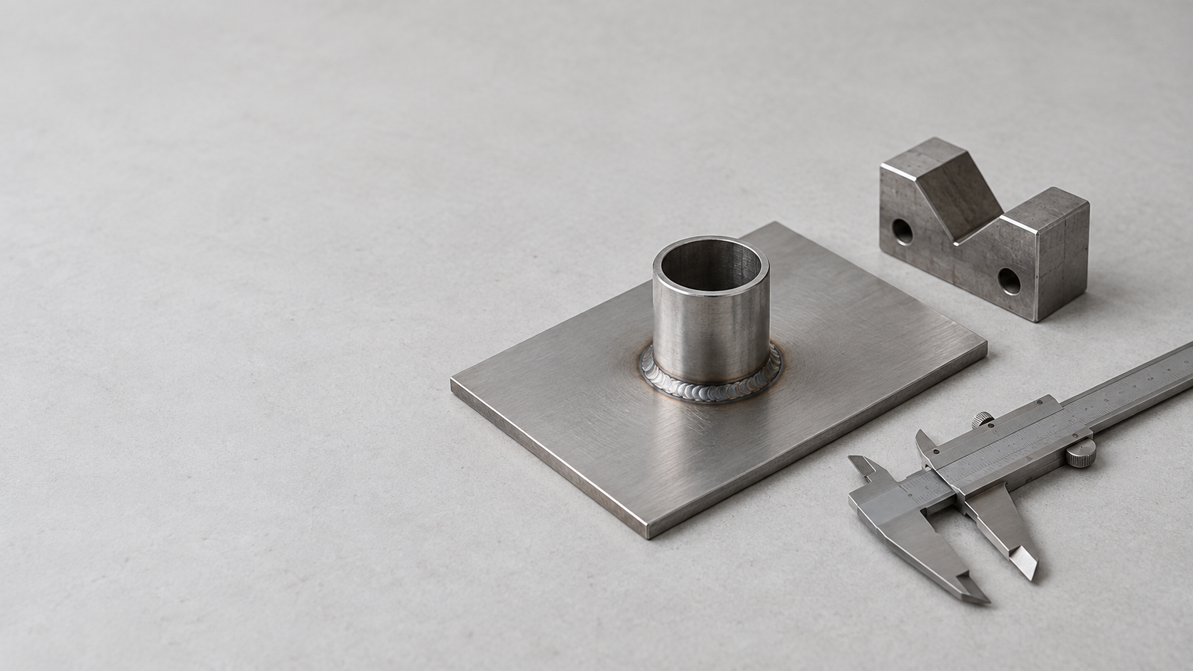
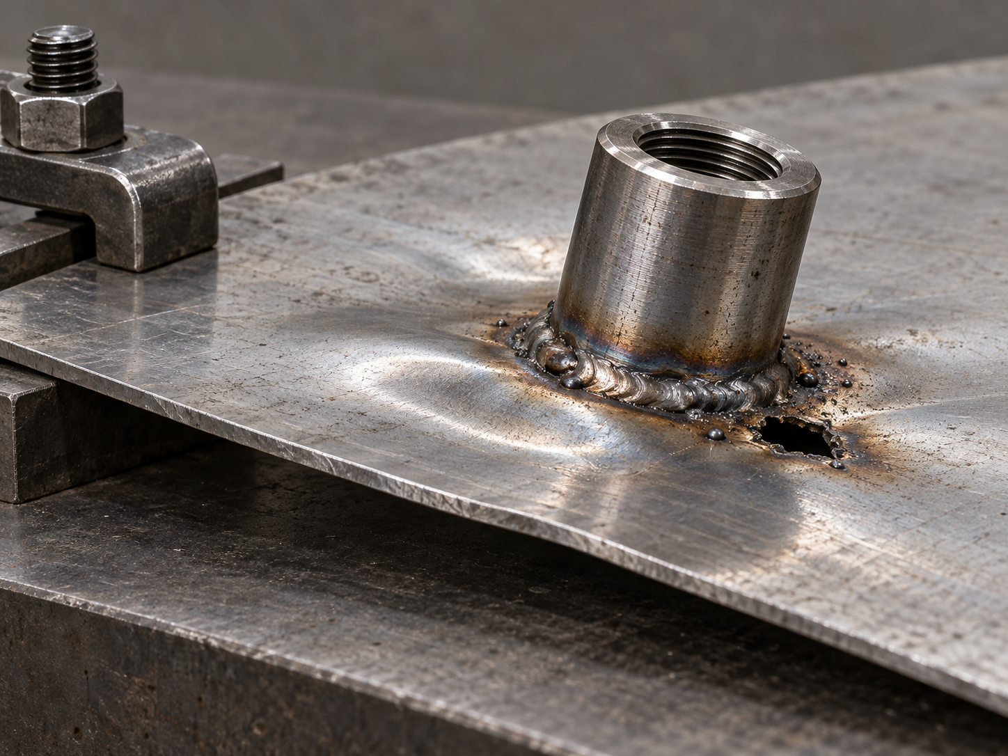
Sheet metal welded bosses are commonly used for bolt mounting, support, locating, or local height buildup. They appear to be simply a boss fixed to a panel surface, but in reality they simultaneously carry position accuracy, connection strength, and assembly function. If the thin sheet receives excessive heat input, it may shrink and warp after welding, and the boss may change from vertical to tilted; concentrated heat can also cause burn-through, forming holes in the weld or adjacent panel surface. Once the boss shifts, fasteners may not fit; if the weld is not fully fused or contains cracks or porosity, loosening or even failure may occur.
The problem is usually not caused by a single welding parameter. The contact relationship at the boss base, sheet thickness, and material determine the tolerable heat input; fixturing and tack welding determine whether position can be maintained during welding; and weld accessibility affects formation, cleaning, and inspection. If the design stage only specifies boss height without stating orientation, datum, loading, and acceptance method, the supplier may deliver a part that cannot be assembled even with an appearance-acceptable weld. Therefore, sheet metal welded bosses should be planned from structural design and process selection through distortion control to post-weld inspection, rather than leaving responsibility to the rework stage.
Welded Boss Structural Design: First Clarify Loading, Weld Accessibility, and Inspection Space
Sheet metal welded boss design cannot just check whether the boss can be placed on the panel surface. First clarify whether it carries locating, support, threaded mounting, or pull-out, shear, or eccentric loads. Different load directions change the contact relationship between the boss and the base panel, the connection perimeter, local panel stiffness, and weld layout. A boss used for locating may focus more on position stability; a boss carrying fastener loads must focus on confirming whether the welded joint can transmit the actual load, and strength cannot be judged by appearance alone.
Sheet Metal Welded Boss Design Must Leave Access for Welding Guns and Fixtures
At the drawing stage, check whether the welding gun or torch head can access the weld, whether the fixture can press the base panel and maintain boss orientation, and whether there is space after welding to clean slag, observe the weld, and place gauges. If the boss is close to a bent edge, deep cavity, or other obstruction, torch posture and electrode space may be limited, and the actually usable welding path may be less than the space shown in the 3D model. Welds should also be avoided in positions that cannot be observed, cannot be cleaned, or are completely obscured after assembly.
Welded Boss Dimensions and Load-Bearing Parameters Cannot Be Applied Without Considering Service Conditions
The boss diameter and height, sheet thickness, weld leg size, and joint configuration should all be confirmed in conjunction with the material, load, installation space, manufacturing method, and project standards. When local stiffness is insufficient in thin sheet, simply increasing the weld size may not solve sheet deformation or tearing; it may instead increase heat input and shrinkage. It is recommended to indicate the boss position, orientation, functional datums, and critical dimensions on the 2D drawing, and to check assembly interference in the 3D model. Load-bearing critical structures should also be verified during prototyping under loading consistent with the actual force direction. Specific parameters should be determined through design calculations, process qualification, or supplier trial-welding results.
Which process is suitable for welding bosses to sheet metal: MIG, TIG, laser, or resistance welding?
There is no fixed “preferred process” for welding bosses to sheet metal. The choice will change depending on the material, sheet thickness, boss configuration, weld accessibility, cosmetic surface requirements, and production volume. The process name cannot replace trial welding; final parameters must still be confirmed in conjunction with project standards, fixturing conditions, and the supplier’s process validation.
How to compare processes for welding bosses to sheet metal
- MIG welding: Generally suitable for common sheet-metal joints where high efficiency and cost-effectiveness are required, with equipment and production takt being relatively easy to match. However, when space around the boss is limited, the torch angle, spatter, heat input, and weld continuity require particular attention.
- TIG welding: Provides finer control of the arc and weld pool. It is suitable for some aluminum and other nonferrous-metal applications and is also useful for welds with high appearance requirements. However, it is slower and more sensitive to operator consistency and surface cleanliness.
- Laser welding: Typically offers a smaller heat-affected zone and lower deformation potential, making it suitable for structures requiring high positional accuracy or appearance quality. However, it is more sensitive to the fit-up between the boss and sheet, joint gap, surface condition, fixture rigidity, and equipment capabilities. It should not be selected solely because of its “low heat input.”
- Resistance spot welding: Suitable for structures where electrodes can be positioned, the lap-joint relationship is clearly defined, and high batch consistency is required. The design must verify that the electrodes can reach the weld points, and the spot-weld layout must be confirmed based on actual pull-out, shear, or eccentric loading. Spot-welding test results cannot be directly treated as the load-bearing standard for all operating conditions.
For example, thin carbon-steel bosses may require particular attention to MIG burn-through, spatter, and post-weld shrinkage, while stainless-steel or aluminum bosses also require consideration of surface condition, thermal conductivity, shielding conditions, and appearance requirements. Before requesting quotations, the supplier should confirm the material and sheet thickness, boss location, torch or electrode accessibility, cosmetic surfaces, production volume, and inspection items, and should observe weld formation, boss displacement, and assembly results through trial welding.
How can heat input and welding distortion be controlled when welding bosses to thin sheet?
On the shop floor, control of boss welding should begin with positional stability rather than immediately starting the weld. Secure the boss with fixtures, locating pins, or dedicated stops, and confirm its height, orientation, and datum position before tack welding. After tack welding, recheck the position to prevent a boss that has already shifted from being “locked in” by continuous welds. The fixture should both restrict the direction of shrinkage and leave sufficient operating space for the welding torch, cleaning tools, and measuring instruments.
Welding sequence and heat input for boss welding
During final welding, a symmetrical, intermittent, or short segmented welding sequence may be used according to the joint configuration, avoiding prolonged concentrated heating in the same area of the thin sheet. In general, the more weld passes and the longer the welding time, the greater the risk of metal shrinkage and sheet warpage. Therefore, increasing the weld size should not be used simply as a substitute for structural and process verification. After completing each segment, allow natural cooling as appropriate for the material and process, then check the boss position and sheet condition.
How should burn-through, shrinkage, and boss displacement be investigated?
- Burn-through or local collapse: First check the sheet thickness, the fit-up gap between the boss and base sheet, heat input, and torch dwell time. Then confirm whether overheating was caused by excessively long continuous welding or repeated local repair welding. Before repair, assess the hole size and the extent of thinning in the surrounding base material to avoid further enlarging the heat-affected zone through multiple repair welds.
- Sheet shrinkage or warpage: Review the weld length, welding sequence, fixture restraint, and cooling sequence. If the welds around the boss are distributed asymmetrically or the fixture cannot support the thin sheet, post-weld shrinkage forces may deform the sheet. First confirm whether the deformation affects the assembly datum, then decide whether to correct, repair, or scrap the part.
- Boss displacement or tilt: Check the locating pins, stops, and tack welds for reliability, and recheck the height, center position, perpendicularity, or orientation before and after welding. If the position was not remeasured after tack welding, or if restricted torch access caused excessive heat input on one side of the weld, the boss may be pulled out of position during continuous welding. After repair, dimensional and assembly inspections must be performed again.
Specific current, travel speed, interpass sequence, and whether preheating is required must be confirmed through trial welding or process qualification based on the material, sheet thickness, boss configuration, and project specifications. At a minimum, remeasure the boss’s critical position and assembly orientation after welding. If deformation exceeds the drawing or functional requirements, first determine whether correction is feasible, then decide whether repair is appropriate; the part must not be accepted based solely on weld appearance.
Common defects in sheet-metal boss welding: porosity, incomplete penetration, excessive reinforcement, and burn-through
An acceptable weld appearance does not mean that the joint meets the load-bearing and assembly requirements. Defect investigation should consider the weld, the heat-affected zone of the base material, the boss position, and actual function at the same time. Record the defect location, and avoid judging quality solely by surface color or weld size.
- Porosity: Appears as holes on the weld surface or in the cross-section. Common causes include oil and moisture on the surfaces of the base material, boss, or welding material; insufficient shielding gas coverage; or airflow interference during welding. First clean the joint and confirm the shielding condition, then check by conducting a trial weld. Critical joints must not be accepted based on appearance alone.
- Incomplete penetration: Effective fusion has not formed at the root, which may be related to the joint gap, root formation, heat input, or welding torch angle. Check the fit between the boss and the plate surface, torch accessibility, and weld continuity. Where necessary, perform cross-sectional or load verification as required by the project.
- Excessive reinforcement and undercut: The weld is visibly built up, or a groove has been cut along the weld edge, usually because the travel speed, arc control, and filler volume are mismatched. Excessive reinforcement does not necessarily indicate higher strength and may also affect assembly and stress distribution. Confirmation should be based on the drawing's appearance requirements, measuring tools, and inspection gauges.
- Burn-through: On thin plates, this typically appears as holes, local collapse, or obvious thinning near the weld, usually caused by excessive heat input, excessive dwell time, or an excessive gap. After discovery, assess whether repair welding could further expand the heat-affected zone, and recheck plate deformation and boss position.
- Cracks and boss displacement: Cracks must be isolated immediately, and the causes—such as material, welding sequence, and shrinkage restraint—must be identified. If the boss is tilted or displaced, trace the issue back to the fixture, tack welding, and welding sequence. After repair, do not merely touch up the appearance; reconfirm critical dimensions, orientation, and assembly function.
How to Inspect the Quality of Welded Bosses: Appearance, Dimensions, Assembly, and Load Verification
Acceptance of welded bosses cannot be based solely on whether the weld appears smooth. It is recommended to conduct layered inspections covering appearance and weld quality, position and dimensions, assembly function, and load verification, each corresponding to different failure risks. Specific acceptance thresholds should be based on the drawing, project standards, and verification plan; uniform values for leg size, deformation, or load capacity should not be applied indiscriminately.
Inspection of Welded Boss Appearance and Weld Quality
First inspect weld continuity, formation, reinforcement, undercut, porosity, cracks, burn-through, and lack of fusion, while also confirming that slag, spatter, and post-weld cleaning meet appearance requirements. Porosity may be related to the cleanliness of the base material or welding material and the shielding condition. Excessive reinforcement, undercut, or uneven formation should be investigated in conjunction with arc control, travel speed, and filler volume. Holes or local collapse in thin plates generally indicate excessive heat input. After an abnormality is found during visual inspection, also confirm whether the defect affects the boss position, plate strength, or subsequent assembly.
Inspection of Welded Boss Dimensions, Assembly, and Load Verification
Dimensional inspection should begin with the assembly datum. Measure the boss position, height, perpendicularity, or orientation, and recheck plate deformation after welding. Depending on the structure, critical dimensions may be confirmed using measuring tools, dedicated inspection gauges, or 3D scanning; displacement must not be judged by visual inspection alone. Then perform functional assembly using bolts, fasteners, mating components, or locating components, and check for interference, looseness, inability to insert, or incomplete locking.
If the boss is subjected to pull-out, shear, or eccentric loads, conduct the corresponding load or destructive verification where necessary. The test direction, clamping method, and boundary conditions should approximate the actual operating conditions as closely as possible. Tensile-shear results for tack-welded joints cannot be directly used as universal acceptance values for all welded bosses. The inspection report should also distinguish between critical dimensions, appearance defects, and functional results to facilitate reinspection after supplier repair.
Drawing and Acceptance Requirements Checklist for Sheet Metal Welding Suppliers
When requesting a quotation or placing an order for welded bosses, do not send only a 2D drawing showing the position. The supplier must at least know the material grade, plate thickness, surface condition, boss position and orientation, as well as whether the boss is intended for locating, support, bolt installation, pull-out, shear, or eccentric loading. If a 3D model is provided, its datums should be consistent with those in the 2D drawing, and the critical assembly surfaces should be clearly identified.
Weld requirements should be specified using the weld symbols, weld types, or dimensional requirements adopted by the project. Do not replace verifiable descriptions with phrases such as “weld securely” or “weld all around.” The drawing should also identify appearance surfaces, permissible plate deformation, and requirements for boss position and orientation, as well as areas requiring cleaning after welding. Specific leg sizes, weld-point layouts, or continuous-weld requirements should be confirmed based on the material, plate thickness, load, and process qualification; uniform values must not be applied indiscriminately.
- Critical dimensions: Boss position, height, perpendicularity, orientation, and relationship to the assembly datum.
- Appearance requirements: Weld continuity, reinforcement, undercut, porosity, burn-through, slag removal, and restrictions on appearance surfaces.
- Functional verification: Actual assembly of bolts, fasteners, mating components, or locating components; when load-bearing is critical, specify pull-out, shear, or other verification methods.
- Inspection plan: Specify the measuring tools, inspection gauges, or tests to be used for critical dimensions, appearance items, and functional verification, and indicate whether sampling inspection or 100% inspection is required.
- Nonconformance handling: Specify whether repair is permitted, which dimensions must be remeasured after repair, and how nonconforming parts are to be isolated and reverified.
Procurement documents should preferably also provide the load direction, boundary conditions, and acceptance criteria. This helps avoid disputes in which “the weld looks acceptable, but the boss cannot be assembled or has insufficient load capacity.” Post-weld reinspection should not focus only on the weld surface; it must also confirm the boss position, orientation, and actual function.
FAQ: Must welded bosses always be continuously welded? Can spot welding or laser welding be used? Is reinspection required after welding?
There is no single welding method for welded bosses that is independent of load-bearing requirements, sealing, accessibility, and drawing specifications. Continuous welding, spot welding, or laser welding should be confirmed based on the material, sheet thickness, boss design, production volume, and tooling conditions, and post-weld reinspection should be used to verify the position and assembly function.
Must welded bosses always be continuously welded?
Not necessarily. If a boss bears a defined pull-out, shear, or eccentric load, or if the connection requires sealing, the weld type should be determined according to the actual load and drawing requirements. For non-sealed structures with relatively distributed loads, intermittent welding or another connection method may be more suitable. However, the number and arrangement of welds must still balance strength, accessibility, and deformation control; it cannot be assumed that “the more welding, the stronger the connection.”
Can spot welding or resistance welding be used for welded bosses?
They can be considered candidate processes, provided that the workpiece offers sufficient access for the electrodes and the spot arrangement covers the actual load path. Attention should be paid to the fit-up between the boss and the sheet, spot locations, sheet-thickness combinations, and batch consistency. Tensile-shear results from spot-welding tests cannot directly replace pull-out or eccentric-load verification under actual operating conditions.
Is laser welding suitable for all sheet-metal welded bosses?
It is not suitable to make a blanket assumption. Laser welding is generally sensitive to joint gaps, the fit between the boss and sheet surface, surface cleanliness, reflectivity, and tooling stability. Before selection, confirm weld accessibility, clamping method, appearance requirements, and material compatibility, and use trial welding to check fusion, burn-through, and positional deformation.
Is post-weld reinspection required for welded bosses?
At a minimum, it is recommended to reinspect the boss position, height, orientation or perpendicularity, as well as its assembly function with bolts, fasteners, or mating components. If the boss carries a critical load, pull-out, shear, or other load verification should also be performed according to project requirements. The inspection items and acceptance thresholds should be specified on the drawing or in the inspection plan; release must not be based solely on weld appearance.
Key takeaways
- First clarify whether the boss carries locating, support, threaded mounting, pull-out, shear, or eccentric loads, then decide the joint type and verification method.
- Welds, welding guns, fixtures, cleaning tools, and gauges need to be considered together at the structural design stage, not remedied only on the production floor.
- The main risks of welded bosses on thin sheet include burn-through, shrinkage, warping, and position shift; fixturing, tack welding, welding sequence, and trial welding are the primary control measures.
- The choice of MIG, TIG, laser welding, and resistance welding depends on material, sheet thickness, boss type, accessibility, appearance requirements, and batch size; the process name cannot replace parameter confirmation.
- Acceptance should distinguish appearance, critical dimensions, assembly function, and load-bearing verification; specific dimensions, weld leg size, distortion limits, and inspection ratios must be confirmed per drawings and project standards.