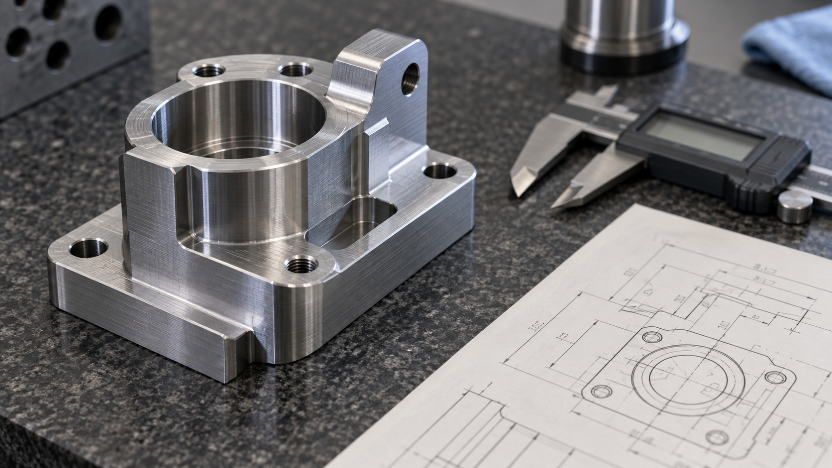
What to Look at First on a German Precision Machined Part Drawing
Material and Heat Treatment Notes Determine the Subsequent Machining Sequence
Surface Roughness Callouts Correspond to Machining Methods, Not Just Feel
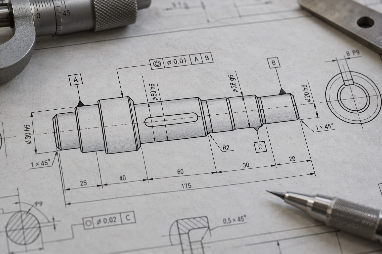
How Material Grades Affect the Process Route for German Precision Machined Parts
On the same German drawing, changing the material from 6061 to 7075, or from stainless steel 304 to 17-4PH, will change cutting parameters, fixturing force, burr morphology, and inspection rhythm. The material grade is not just a line of text in the notes column; it is the first fork that determines the process route. Material notes for German precision machined parts are often written in great detail: condition, heat treatment, and even whether the stock form is bar or plate—these directly change tool wear rates and thermal deformation, which in turn affect which tolerance band you can reliably hold.
Aluminum Alloys: Where 6061 and 7075 Differ in Machinability
6061-T6 is the most common aluminum grade in German precision machined parts: stable machinability, smooth chip evacuation, relatively easy control on thin-walled parts, and achieving Ra below 1.6 after fine milling is usually not difficult. 7075-T6 has higher strength but is harder and more brittle, wears tools faster, and with slightly higher feed tends to leave chatter marks on thin walls; for the same geometry, switching to 7075 often requires reducing feed, increasing spindle speed, and even switching to sharper multi-flute end mills.
A common industry practice is: for 6061 thin-walled parts, use soft jaws or vacuum fixturing, with clamping force controlled at a medium-low level; 7075 relies more on auxiliary support and symmetrical material removal to avoid warping after stress release. In terms of achievable tolerances, fine-milled mating surfaces commonly reach around ±0.02 mm in the industry, but this is not a commitment—when the drawing specifies ±0.01 mm, you must first look at wall thickness and datums, then confirm with the workshop.
Stainless Steel and Brass: Thermal Deformation and Burr Morphology Determine Tooling in Reverse
304 work-hardens noticeably, with heat concentrated in the cutting zone; continuous passes are safer than interrupted passes. 316 contains molybdenum and has a stronger tendency to stick to the tool, so cooling often needs to start with high-pressure internal cooling dedicated to stainless steel; otherwise, hole-wall roughness will be unstable. 17-4PH differs greatly in machinability between the solution-treated and aged conditions. If the drawing only says "17-4PH" without specifying the condition, this must be clarified at the quoting stage, because once aged, hardness rises and tooling and parameters must be rearranged.
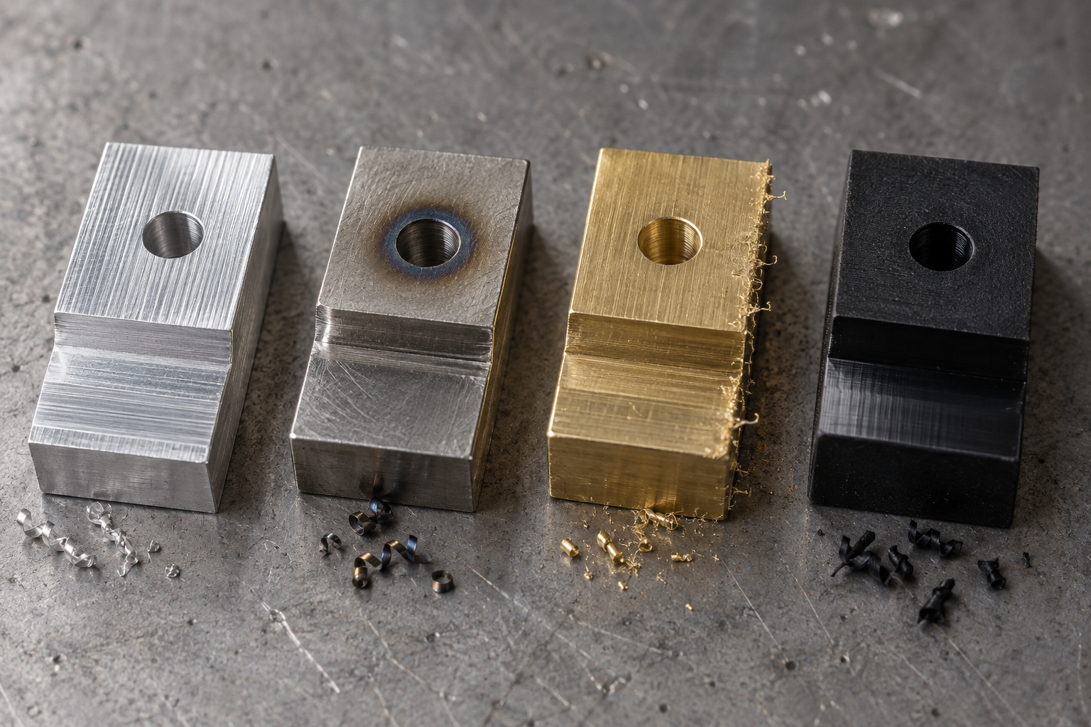
Brass has excellent machinability, but its burrs are soft and tough, making deburring more labor-intensive than cutting; edges of small holes and narrow slots tend to flare, and a caliper squeeze during inspection can deform them. Engineering plastics follow another logic entirely: POM is dimensionally stable with a smooth machined surface, but slightly higher clamping force leaves marks; PEEK is tough and heat-resistant, but chips evacuate poorly during cutting and tend to wrap around the tool; PA absorbs moisture and its dimensions drift, so incoming material condition and post-machining resting time must be aligned at the drawing stage.
Three Things That Must Be Reassessed After Changing Material
The first is clamping force. Aluminum parts are prone to crushing, stainless steel parts to tool deflection, and plastic parts to creep—the same set of soft jaws cannot use the same clamping torque across different materials. The second is feed and cooling. Plastics and some stainless steels require more thorough chip evacuation at high speeds; otherwise, recutting will scratch the already-machined surface. The third is inspection method. Thin-walled brass and aluminum parts deform easily with contact gauges, so the industry often switches to vision systems or CMM touch probes with light contact; for plastic parts, ambient temperature and humidity during measurement must be considered, and measuring after a resting period is closer to the true dimensions.
These adjustments may seem trivial, but most rework on German precision machined parts is not due to insufficient machine accuracy, but because the material changed and the process route did not change with it. Confirm the material grade, condition, and stock form before quoting, and only then will the subsequent fixturing and inspection plans have a basis. For specific achievable tolerances and surface grades, it is recommended to check item by item against the drawing with the workshop rather than directly applying the parameters from the previous order.
Process Selection: The Boundary for German Precision Machined Parts from CNC to Vacuum Casting and Injection Molding
When German customers request quotes, the drawing rarely says "make it with CNC," but if a supplier quotes purely on the intuition that "the higher the precision, the more it should be CNC," they often hit pitfalls in the first batch. What truly determines the process is the intersection of batch size, geometric feasibility, and the unit-cost curve, not a ranking by precision level. For the same aluminum housing, a one-off CNC milling job may be faster and cheaper than opening a mold for injection molding; at an annual volume of tens of thousands of pieces, CNC's per-unit machining time and tool wear push costs up, while injection molding's mold amortization is diluted. The first step in selecting a process for German precision machined parts is to ask "how many of these are you planning to make," not "how tight is the tolerance."
One-off to Small Batch: CNC Milling and Turning Are the Default Starting Point
For one piece, a few pieces, up to dozens of pieces, CNC milling and turning are usually the most stable choice. No mold is needed, the fixturing plan can be adjusted piece by piece, and materials from aluminum and stainless steel to engineering plastics can be switched directly. Complex internal cavities, deep slots, and multi-face machining can be completed on five-axis machines or through multiple setups. A common industry judgment is: when the batch is within dozens of pieces, the geometry is complex, and the material varies, CNC's lead time and unit cost are usually lower than the mold-opening route. But note that CNC's unit cost hardly decreases with batch size; the machining time for the twentieth piece differs very little from the first—this is the fundamental boundary between it and injection molding or vacuum casting.
Complex Internal Cavities and Lightweighting: The Trade-offs of 3D Printing
When a part has internal channels, lattice lightweight structures, or closed cavities that traditional tools simply cannot reach, 3D printing (FDM, SLA, SLS, MJF, DMLS) can bypass the constraints of fixturing and tool accessibility. But German customers often press on directionality for metal printed parts: interlayer strength in SLS/MJF, support removal and post-processing in DMLS all affect final dimensions and surfaces. Printed parts usually have wider tolerance bands than CNC, and mating surfaces often still need stock left for a finishing pass. So in German precision machined parts, 3D printing plays more of a role in "making the geometry feasible" rather than replacing CNC's precision role.
Small-Batch Appearance Parts: Where Vacuum Casting Fits
If the part is an appearance part such as a housing or panel, with a batch of dozens to hundreds of pieces, and the customer wants to see color, texture, and assembly feel, vacuum casting (urethane casting) is often more cost-effective than CNC. Silicone molds can replicate the surface detail of the master pattern, and polyurethane materials can be color-matched and hardness-tuned. Its limits are: vacuum-cast parts are less dimensionally stable than injection molded parts and may shrink or age over long-term use; mold life is limited, and the silicone mold wears after casting dozens to hundreds of pieces. So it is a transitional process for "small-batch validation of appearance and assembly," not the endpoint of mass production.
Entering Mass Production: The Evaluation Threshold for Injection Molding and Tooling
Only when annual volume reaches thousands or tens of thousands of pieces does injection molding's unit-price advantage truly emerge. But mold opening is a one-time investment, and mold structure, draft angle, wall thickness uniformity, and gate location all lock in the room for subsequent modifications. If a German customer's drawing does not specify draft and has large wall thickness variations, DFM feedback must be provided before injection molding; otherwise, the cost of mold changes during trial runs will eat up the batch savings. A common industry threshold is: when annual volume of a plastic part reaches several thousand pieces or more, and the geometry allows draft and uniform wall thickness, injection molding is more economical than CNC or vacuum casting; the specific number must be confirmed according to part size, mold complexity, and material, and cannot be generalized.
Sheet metal enclosures and brackets: the impact of bending and welding on precision
For parts like enclosures, brackets, and mounting plates, sheet metal (laser cutting, bending, welding) is often faster than full CNC milling. But sheet metal follows a different precision logic: bend springback, the relationship between bend radius and sheet thickness, and welding heat distortion all cause hole positions and flatness to deviate from the drawing. If a German drawing specifies position tolerance or flatness, sheet metal parts often require secondary machining of holes after bending, or welding fixtures to control distortion. Quoting sheet metal parts as "low-cost CNC parts" is a common misjudgment in German precision machined parts.
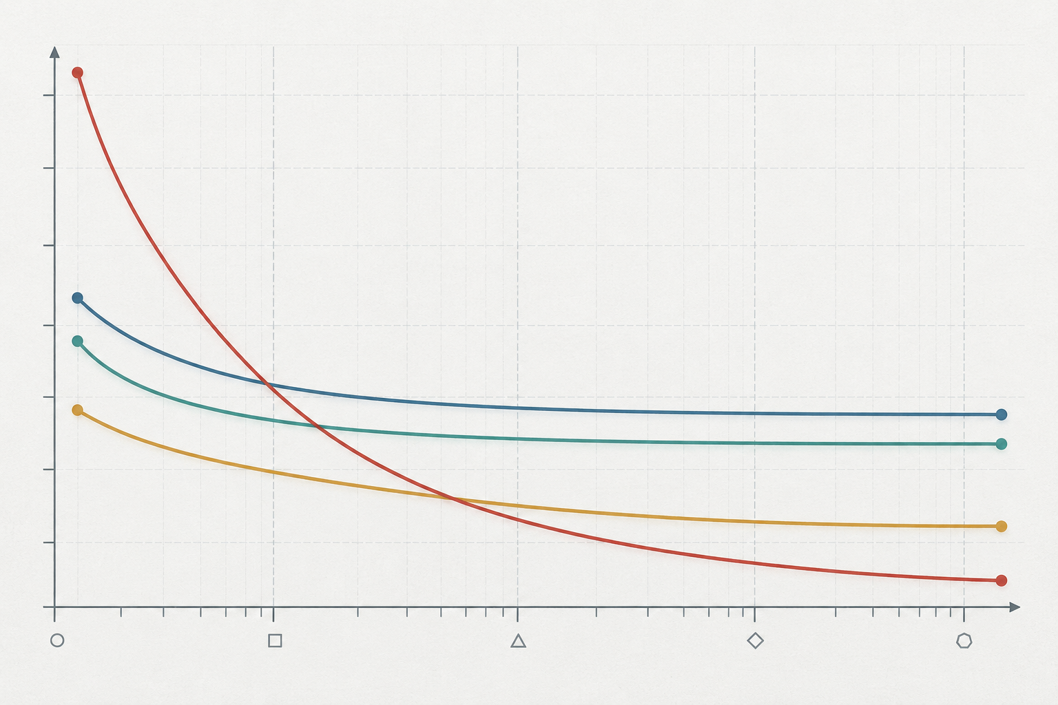
Looking at these routes together, selection is not about "which one is more precise," but "which one has the lowest overall cost and is most geometrically feasible at the target volume." The process boundary for German precision machined parts usually falls in the range where volume climbs from single digits toward the thousands: CNC handles one-offs and small batches, urethane casting handles appearance validation, injection molding takes on volume, sheet metal handles plate-type structures, and 3D printing fills geometric blind spots. Once the drawing is confirmed, you can use AI chat quoting to clarify volume, material, and key tolerances in one go, giving process decisions a solid basis.
Fixturing, datums, and tolerance chains: where the precision of German precision machined parts comes from
The tolerances on a drawing are the result; fixturing and datums are the cause. With the same machine and the same tool, changing the fixturing scheme can easily produce a measured result that differs by a full tolerance grade. Most precision disputes over German precision machined parts are not about machine accuracy, but about "how it is clamped, what datum is used, and how tolerances stack."
Single setup vs. multiple setups: how errors accumulate
Each additional setup introduces a positioning error. After a part is flipped, the dimensions on the second face are measured relative to a second datum, and the tiny deviation between the two datums stacks directly onto the overall dimension. This is why German drawings often require "machining from the same datum"—the datum symbols on the drawing are not decoration, they constrain the sequence of operations.
The practical criterion is simple: first count how many setups the critical dimensions span. If a mating dimension runs from face A through to face B, evaluate whether to complete it in a single setup, or to design process bosses or process holes as a unified datum. A common industry practice is to complete critical mating surfaces within a single setup as much as possible; other non-mating surfaces may be split across operations with appropriately relaxed tolerances. Polyhedral parts often use hexahedral datum transfer, but each transfer requires recalculating the accumulated error.
Thin-wall parts and auxiliary support: preventing distortion is more practical than chasing precision
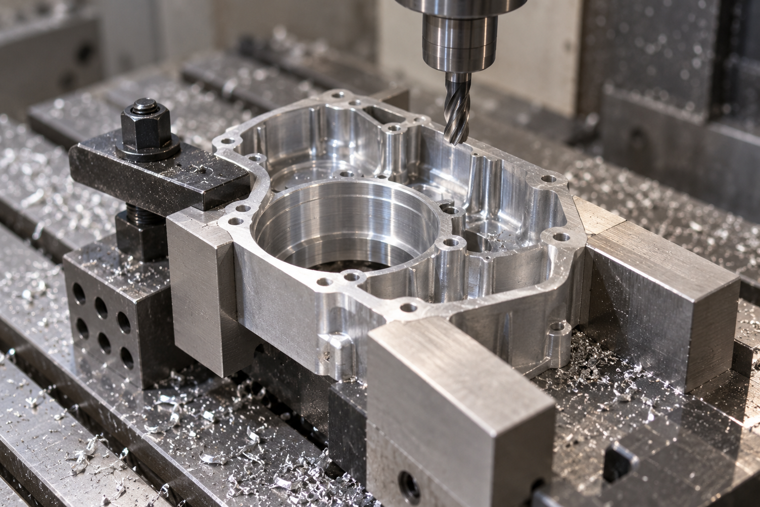
Dimensional drift in thin-wall parts mostly comes not from cutting, but from clamping force. Clamp a cylinder hard in a three-jaw chuck and it springs back into an oval when released; clamp a thin plate in a vise and it warps after milling once released. Many housings, covers, and brackets in German precision machined parts fall into this category.
The countermeasure is staged force reduction: during roughing, use soft jaws or dedicated fixtures to absorb the large cutting forces; before finishing, switch to light clamping, and when necessary use vacuum fixturing instead of mechanical clamping so the clamping force is evenly distributed. For internal cavities, fill with wax, low-melting-point alloy, or removable supports to reduce tool deflection and chatter. The criterion is: if the part measures very differently after the clamp is removed than it does while clamped, the fixturing scheme needs to be redone rather than continuing to adjust tool compensation.
Tolerance chain stacking: a conforming individual part does not mean a conforming assembly
When multiple parts are assembled in series or parallel, their tolerances stack. Three parts each marked ±0.05 mm can produce a total assembly deviation approaching ±0.15 mm—every individual part conforms, yet the assembly is out of tolerance. This is one of the most frequently raised issues after delivery of German precision machined parts.
The order of handling is: first identify the functional mating surfaces (the surfaces that truly determine assembly and motion), then grade the tolerance bands by function. Tighten the mating surfaces, follow with locating surfaces, and relax non-mating surfaces according to machining capability. Where a unified datum can solve the problem, do not rely on tightening dimensional tolerances. When necessary, change the closing-link dimension into an adjustable structure, or specify selective fitting or group assembly.
| Functional mating surfaces (shaft holes, guideways) | Tightened, set according to the nature of the fit | Completed in a single setup, unified datum, verified by CMM or plug gauge |
| Locating surfaces, mounting surfaces | Medium | Splitting across operations allowed, watch for datum transfer errors |
| Non-mating outer shapes, lightening cavities | Relaxed | Soft jaws, vacuum fixturing allowed, sampling inspection with calipers |
| Thin-wall continuous contours | Set by function, control distortion first | Light clamping plus auxiliary support, re-measure after unclamping |
Fixturing schemes and tolerance grading are best confirmed before quoting. Mark the critical mating surfaces, datum symbols, and series dimensions so that process planning and inspection share a common language. If the drawing only says a vague "high precision," first ask the customer to identify the functional surfaces—the communication saved at this step is often far more than what is saved later on machine adjustment.
Inspection and gauge alignment for German precision machined parts
The inspection question for German precision machined parts is usually not "whether to use a CMM," but "how the tolerance frames on the drawing are realized on the gauge." The root cause of many rework orders is not that the machine failed to achieve the requirement, but that at acceptance the two sides are talking about the same thing with different gauges and different datums. The inspection plan must be settled at the drawing-reading stage; you cannot wait until the first article comes out to decide what to measure.
Which gauge goes with which feature
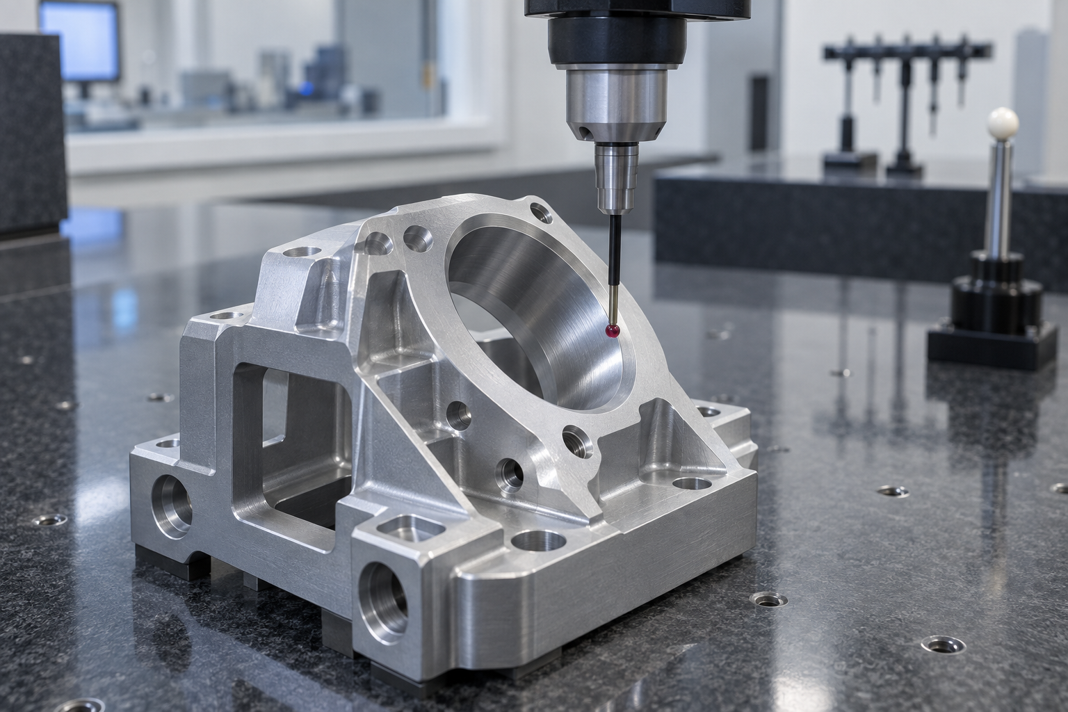
The basic principle for choosing a gauge is: the gauge must faithfully reproduce the datum and tolerance definition on the drawing, not merely "be able to read a number." For simple dimensions such as outer diameter, thickness, and depth, calipers and micrometers are sufficient, provided the gauge's reading resolution is clearly better than the tolerance band being measured. A common industry practice is to keep gauge resolution at around one-tenth of the tolerance band; actual measurement capability is often also affected by temperature, operator technique, and workpiece rigidity, so the specific factor should be confirmed against the drawing and workshop conditions. For hole diameters and threads, prioritize plug gauges, ring gauges, or thread gauges, because they judge "go/no-go," which is closer to the result of functional assembly than a reading.
Geometric tolerances require a CMM or vision system. Coaxiality, position, and parallelism cannot be measured with calipers; a datum coordinate system must be established before evaluation. Position tolerance deserves special attention: if the drawing specifies maximum material condition (MMC), the CMM software must calculate according to the corresponding compensation method, otherwise the computed deviation may be overly conservative or overly loose. Such callouts are very common on German drawings, and it is worth confirming which principle is used when the drawing comes in.
Division of labor among first article, sampling inspection, and 3D scanning
First article inspection (FAI) must cover all critical characteristics on the drawing, including datums and geometric tolerances, not just dimensions. After the first article passes, process sampling inspection watches for drift—tool wear, thermal distortion, fixturing repeatability—which may not show up on a single part but emerges once volume production starts. There is no universal answer for sampling frequency; it depends on tolerance band width, material stability, and volume, and is usually agreed between process engineering and the customer.
For German precision machined parts with freeform surfaces, complex contours, or only a physical part without a complete drawing, 3D scanning is more suitable. The value of scanning lies in color-deviation comparison—overlaying the measured point cloud with the CAD to see the deviation distribution locates distortion regions faster than point-by-point measurement. However, scanning accuracy is affected by surface reflectivity, spray coating thickness, and stitching errors, so final acceptance judgment usually still comes back to a CMM or dedicated gauges. If the inspection plan can be aligned with the customer before quoting, there will be far fewer disputes later; the combined use of 3D scanning capability and conventional gauges can be discussed together during the drawing review stage.
Surface roughness, heat treatment, and stress relief: the sequence of finishing operations
Dimensional drift in German precision-machined parts is usually not caused by miscalculation during cutting, but by getting the sequence of finishing operations wrong. Rough machining allowance, stress relief, finish machining, heat treatment, re-finishing—once these steps are interleaved, dimensions that measured within tolerance earlier can go out of tolerance after the final operation. When reading the drawing requirements, first distinguish which are final dimensions and which are merely intermediate states.
Place stress relief after rough machining and before finish machining
Residual stress inside castings, forgings, and bar stock redistributes after a large amount of material is removed. After rough machining removes most of the allowance and the part is "hollowed out," scheduling a stress relief (natural aging or stress-relief annealing) before entering finish machining can minimize subsequent deformation. Conversely, finishing first and then adding stress relief is equivalent to sending already-formed dimensions into a furnace to be reshuffled.
Parts with poor rigidity, such as slender shafts, thin-walled rings, and large flat plates, are especially sensitive to sequence. In allowance allocation, the finish machining allowance should not be too large—a large allowance means large cutting forces, and after stress relief another cut is needed, which instead adds one more setup error.
After heat treatment, a finish machining correction is often needed
Quenching, aging, and nitriding bring dimensional and shape changes: after quenching, hardness increases and cutting becomes difficult, accompanied by volume changes and warping; the nitrided layer is thin and hard, so usually only minimal grinding or lapping is done. Therefore, a common practice is to leave correction allowance before heat treatment, and after heat treatment use grinding, lapping, or slow wire EDM to bring key surfaces back into the drawing tolerance band.
If the customer requires "heat treatment as the final state," the drawing must clearly specify the surfaces that will not be machined after heat treatment, and accept that the dimensions of those surfaces are governed by the heat treatment result. Mixing the two on one drawing is the easiest way to end up arguing during acceptance.
Correspondence between Ra callouts and machining methods
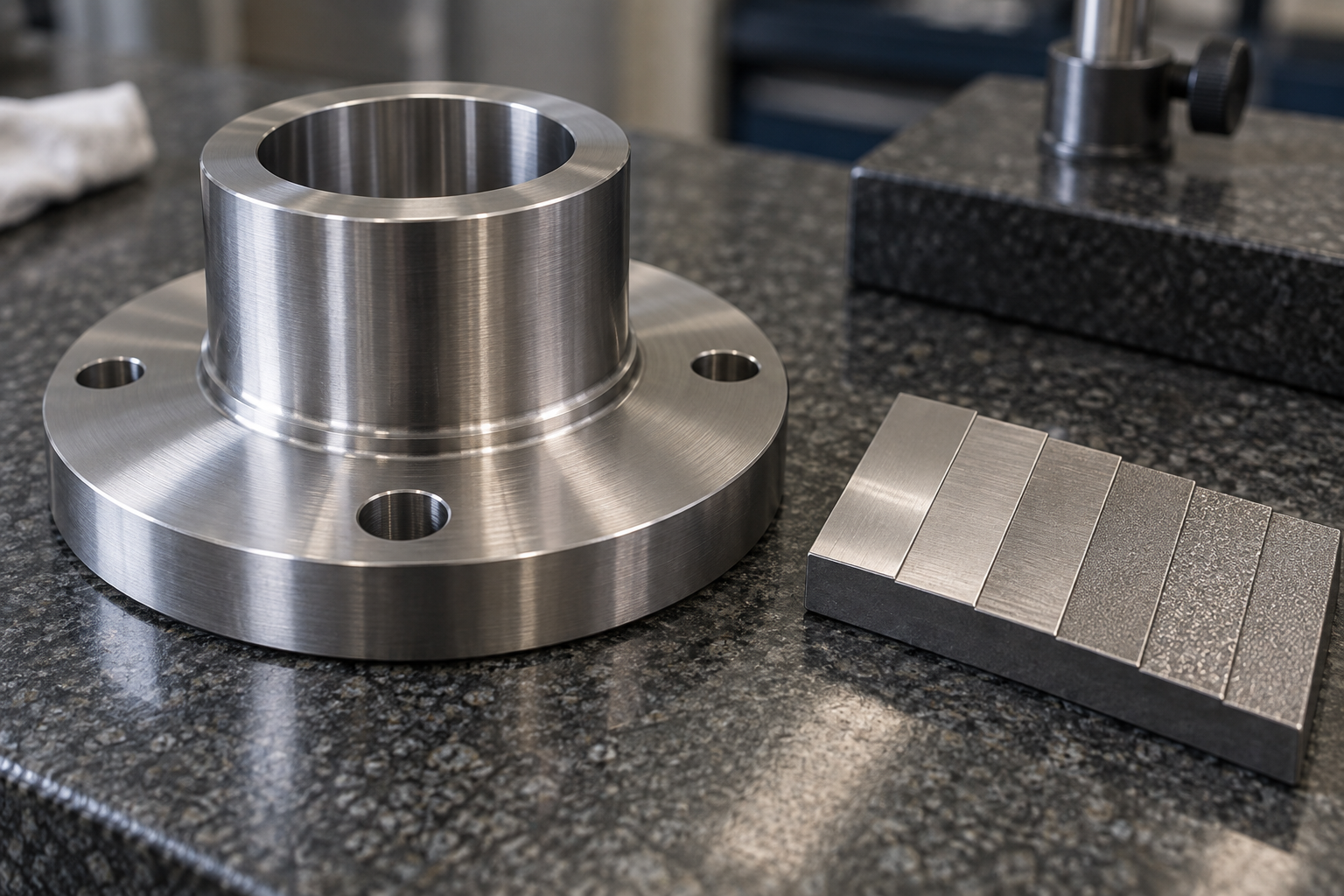
Surface roughness is not better the smoother it is; it is tied to function. Common industry correspondences can serve as reference: ordinary milling about Ra 3.2–1.6, fine milling about Ra 1.6–0.8, grinding about Ra 0.8–0.4, and lapping/polishing can reach below Ra 0.2. Values must be confirmed according to the drawing and actual workshop conditions; the upper limits achievable vary with different materials, tools, and machine tools.
There are two more easily overlooked points: first, the surface condition before anodizing, blackening, or electroplating directly affects appearance; if pretreatment is not fine enough, tool marks will be amplified after treatment; second, sealing surfaces and sliding fit surfaces have requirements for texture direction, and looking only at the Ra value is not enough—the machining texture direction must be specified.
Fix the sequence into one main line: rough machining → stress relief → semi-finish machining → heat treatment → finish machining/grinding → surface treatment. Each step leaves controllable allowance and datums for the next, and the rework rate of German precision-machined parts will drop noticeably.
Drawing specifications to confirm before quoting and common rework points
Material and condition: without condition, there is no process route
Key tolerances and datums: grade functional surfaces first; do not force non-functional surfaces to hold tight limits
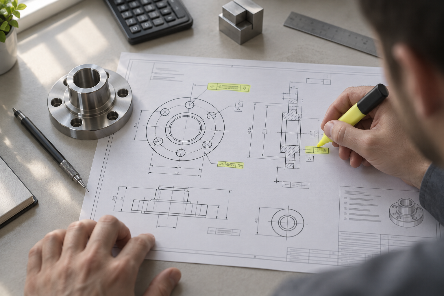
Surface, heat treatment, and inspection methods: state the acceptance criteria clearly
Quantity and batch: batch size determines the process boundary
Common rework points: most occur in finishing and details
- Thin-wall deformation: when wall thickness approaches the tool diameter, cutting forces and clamping forces both cause the part to deflect, and dimensions spring back after finish machining. Auxiliary support or adjusted toolpath strategy is needed.
- Deep-cavity chip evacuation: in deep cavities, chips cannot be evacuated and will scratch machined surfaces or cause tool chipping. Confirm whether high-pressure coolant or layered chip evacuation is available.
- Thread and hole position deviation: after multiple setup operations, hole positions accumulate deviation, and the thread pilot hole and thread form do not match. Inconsistent datums are the main cause.
- Dimensional change after anodizing: anodizing consumes dimensions, especially noticeably on thin-walled parts. Surfaces with fit requirements need reserved allowance or machining after anodizing.
Common questions about German precision-machined parts
The following questions basically all arise after reading the drawing and determining the process. The answers give judgment boundaries, not promised values—for a specific German precision-machined part, the drawing, tolerance frames, and actual workshop capability still govern.
How do German drawing annotation habits differ from common domestic drafting practices?
The difference is usually not in the symbols themselves, but in information density and default conventions. German drawings often write datum symbols, geometric tolerance frames, material condition (such as quenched and tempered, aged), and heat treatment hardness very completely, and dimension chains also tend to be annotated by functional surface rather than by machining sequence. Some domestic drawings leave key fit dimensions to verbal communication, while German drawings tend to treat "the drawing as the acceptance basis."
When implementing, first confirm three things: whether the datum is unique and achievable by clamping; whether the datums in the geometric tolerance frames are machining datums (if not, conversion is required); and whether material condition and heat treatment are written in the title block or in notes. If these three items are read incorrectly, subsequent clamping and inspection will also deviate.
If the material is changed to a more machinable grade, will acceptance be affected?
Yes, and it is often not a dimensional issue but a performance issue. Switching to a free-machining grade (for example, leaded or high-sulfur free-machining steel, or certain aluminum with machining additives) usually improves chip evacuation, reduces tool wear, and makes surface roughness more stable, but strength, corrosion resistance, weldability, and subsequent surface treatment (anodized color, coating adhesion) may change.
If the drawing specifies the grade and condition, substitution is a deviation and requires written customer confirmation. If it is only internal trial production, it can be changed, but acceptance still follows the original drawing's mechanical and surface requirements; do not use "easier to machine" as a reason to relax acceptance.
For small-batch German precision machined parts, is it worth going straight to injection molding tooling?
It depends on the batch size and geometry. For dozens to a few hundred pieces, CNC milling/turning or vacuum casting is usually more cost-effective, because it saves the mold cost and trial-mold cycle; when the geometry has complex internal cavities, lightweight lattice structures, or conformal cooling requirements, 3D printing is also often faster than tooling during the prototyping stage.
Injection molding is only cost-effective when the batch size is stable, the per-piece cost is sensitive to mold amortization, and the requirements for the appearance and dimensional consistency of the plastic part are clear. The deciding point is: whether the mold cost divided by the estimated total quantity is significantly lower than the difference in per-piece machining cost. This number must be calculated based on actual quotes, not by feel.
The customer specifies tighter tolerances than the function requires. How should we communicate?
First distinguish which are functional mating surfaces and which are merely external dimensions. Break down the tolerance chain, point out which dimensions, when stacked in series, determine the assembly clearance, and the rest can be relaxed. Speak with concrete costs: tighter tolerances usually mean more setups, slower feed rates, and a higher inspection ratio, and both cost and lead time will go up.
When communicating, offer alternatives instead of just saying "it can't be done." For example, relax the overall tolerance and tighten only the critical mating areas, or add a grinding/finish milling operation specifically to hold those few dimensions. In the end, the version confirmed by the customer prevails; do not change the drawing on your own.
What does an inspection report generally include?
The common one is a first article inspection report plus actual measured values for critical dimensions: item number, drawing nominal value, upper and lower deviations, actual measured value, and the measuring instrument used (CMM, vision measuring machine, micrometer, plug gauge, etc.). For geometric tolerance items, the datum establishment method and measurement results will be stated. For freeform surfaces or reverse-engineering comparison scenarios, a 3D scan color deviation map may be attached.
The scope of the report must align with the drawing's acceptance criteria—items not required by the drawing are usually not fully measured in the report. If the customer needs a specific format or specific items, this should be stated before quoting, not added after shipment. The specific inspection capabilities and report format are confirmed on a project-by-project basis.
Key takeaways
- The difficulty of German precision machined parts often lies not in a single tolerance value, but in the overall arrangement of datums, fixturing, and tolerance chains.
- Material feasibility determines the process route: change the material on the same drawing, and the tooling, cutting parameters, and inspection methods must all change accordingly.
- Grading tolerance bands by function and tightening only the mating surfaces is often cheaper and more stable than tightening the entire drawing.
- Inspection methods must be aligned at the drawing stage; if gauge capability is insufficient, no matter how strict the callouts are, acceptance is impossible.
- Surface roughness, heat treatment, and stress-relief operations have a sequence; get the order wrong and dimensions will drift.



