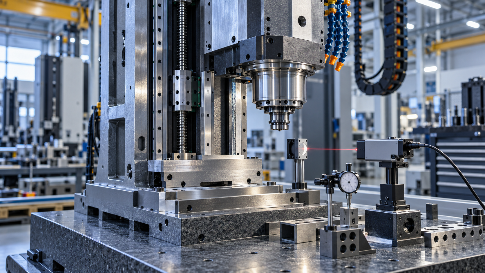
The current state of CNC machine tools: competition in machine tool manufacturing has shifted from "whether you have it" to "whether it is stable"
Let's start with an easily overlooked fact: today, if you walk into any machine shop of a certain scale, you will hardly see a factory "without CNC machine tools." The real difference is not whether that model appears on the equipment list, but whether the same machine tool produces the same part today and three days later.
This is the shift in the focus of competition in machine tool manufacturing. Over the past two decades, the industry solved "whether there is automation"—replacing hand-cranked handles with program control, and conventional machine tools with CNC machine tools. The production and sales volume of domestic CNC machine tools has ranked among the world's top for many consecutive years, and the overall scale of the industrial mother machine industry has long been in the first tier. Today, the signals at exhibitions are very concentrated: turn-mill multi-tasking, five-axis simultaneous machining, multi-spindle, on-machine measurement, and adaptive control—almost every booth is talking about the same thing: not whether it can move, but whether it moves stably, accurately, and consistently over long periods.
To understand this competition, you can focus on three observation points.
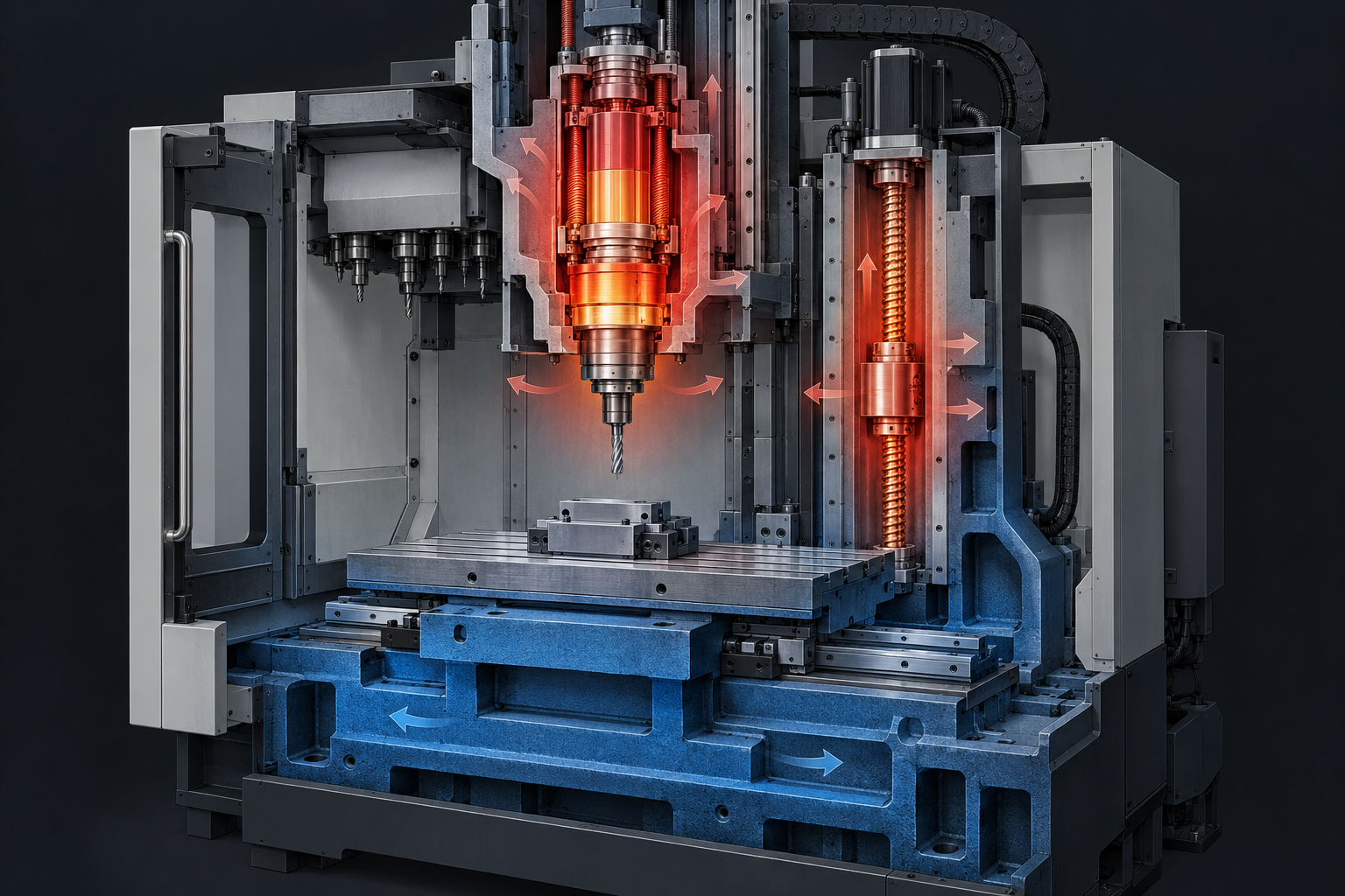
- Machine body precision and thermal stability. Positioning accuracy is written in the catalog; repeat positioning accuracy is written in long-term use. The spindle heats up when it rotates, the ball screw heats up after running for a while, and the bed also deforms under the influence of ambient temperature. Whether a machine tool can be designed with thermal symmetry, oil cooling or water cooling, and key components enclosed in a constant-temperature environment directly determines how much the dimensions it cuts in the morning differ from those in the afternoon.
- CNC systems and process software. A system does more than execute G-code. Interpolation algorithms, servo gain matching, look-ahead control, and tool compensation determine whether corners will be overcut and whether feed rates can be raised on difficult-to-machine materials. Process software, meanwhile, ties CAM parameters, tool libraries, and post-processing together, determining whether programs need few changes when switching machines or systems.
- Batch consistency. This is the most practical point. No matter how high the machine tool precision is, if tool wear is judged by people, fixturing relies on feel, and once the first article passes it is run all the way through, dimensions will slowly drift over a batch. Whether online measurement, tool life management, and SPC can be built into the process is the watershed that distinguishes "the sample can work" from "mass production can work."
Take a common scenario on the shop floor. Two machining centers of the same model make the same batch of aluminum alloy housings. Both first articles pass, with hole diameters and position tolerances in the middle of the tolerance band. By the third day, one is still within the tolerance band, while the other is already out of tolerance. After investigation, the problem is not in the program, nor in the tool grade, but in coolant temperature control, spindle thermal deformation compensation, and the operator's tool-setting habits after changing tools. This is the concrete meaning of "whether it is stable"—not the extreme capability of a single machining operation, but the ability to keep dimensions within the tolerance band over a period of time.
So when looking at machine tool manufacturing and the machining future, the first judgment to remember is: the nominal precision of a machine tool is the ticket to entry, while long-term stability is the real competitiveness. For those making parts, when choosing a supplier, asking "how do you control dimensional drift over three consecutive days of machining" is often more revealing of their level than asking "what machine tools do you have."
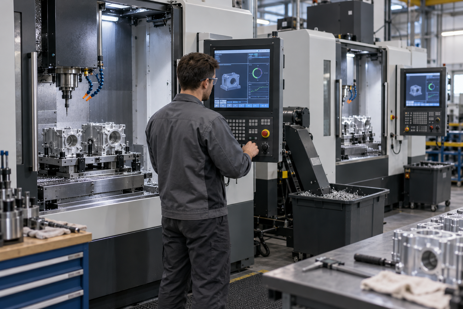
Precision is not a machine tool solo: tolerance band, thermal deformation, and fixturing each take a share
Many people, the first time they look at a machine tool catalog, focus their attention on numbers like "positioning accuracy ±0.002 mm," and then assume the part can achieve that number. In the actual shop, the machine tool is only one link in the entire error chain. What final size a part lands at is the combined result of machine tool geometric accuracy, thermal deformation, fixturing deformation, tool wear, material springback, and the inspection method. When discussing machine tool manufacturing, machining the future, the first thing that cannot be avoided is this: equating machine tool accuracy directly with part accuracy is the mistake an outsider is most likely to make.
Positioning accuracy and repeat positioning accuracy are two different things
Positioning accuracy describes the deviation between the commanded position and the actual reached position, while repeat positioning accuracy describes the degree of scatter in the landing point when the same command is executed repeatedly. For batch machining, the latter is often more critical: a machine tool with stable repeat positioning accuracy, even if its absolute position is slightly offset, can still keep the entire batch of parts within the tolerance band through first-article compensation; conversely, a machine tool with good absolute accuracy but poor repeatability has no problem making a single part, but will scatter when making one hundred. So when looking at equipment specifications, do not just look at the prettier number; look at the test conditions it corresponds to—no load, constant temperature, low speed—which are very far from the actual cutting state.
Thermal deformation: dimensions slowly drift away over the course of a day
Heat generated by spindle operation, frictional heat from the screw-nut pair, heat carried away by chips, and the day-night temperature difference in the shop all cause micron-level thermal elongation in the machine tool structure. The typical manifestation is: the first part in the morning is qualified, at noon the size is a few microns too large, and in the afternoon it comes back a little. For hole-shaft fits of IT7 grade or above, this drift is enough to make half of a batch of parts out of tolerance. Common countermeasures are warm-up running-in after startup, placing critical operations in a constant-temperature room, using cutting fluid and oil cooling to control spindle temperature rise, and leaving thermal compensation in the program. These practices are process judgments, not something that can be solved automatically by buying an expensive machine tool.
Deformation introduced by fixturing is often greater than machine tool error
This is especially obvious for thin-walled parts, slender shafts, and frame-type parts. If the vise clamping force is too large, the part springs back after release; if the soft jaws are not turned true, roundness directly goes off; a vacuum chuck is effective for thin plates, but its suction is uneven for parts with curved surfaces; a dedicated fixture can solve positioning, but may direct the cutting force toward the direction of weakest rigidity. Common engineering practices are to control clamping force, add auxiliary supports, separate rough and finish machining to release stress, and when necessary fill with low-melting-point alloy or wax. To judge a supplier's process level, looking at how it talks about fixturing is more effective than looking at how many machines it lists.
Here is a commonly seen reference range in the industry, only as a scale for judgment, not a promise by anyone: general CNC machining dimensional tolerances often fall within ±0.01–±0.05 mm, and the surface roughness of fine turning and fine milling is commonly Ra 0.8–3.2 μm. How much can actually be achieved depends on the drawing tolerance band, material, part rigidity, datum selection, and inspection method, and must be confirmed according to the drawing. Appropriately relaxing non-critical dimensions is often more effective at controlling overall cost than stubbornly struggling over one dimension—this is also the criterion to be expanded in the following sections.
The first main line of machining's future: the machine tool body moves toward "compound + high rigidity + thermal stability"
When discussing the future of machining, the easiest direction to go off track is to stare only at the CNC system and software. But standing in the shop and looking, the first ceiling on part accuracy is always the machine tool body: whether it is rigid enough, whether it will thermally expand, and whether it can reduce fixturing. In recent machine tool exhibitions, compound models have appeared intensively, and industry discussion has shifted from "does it have five axes" to "can this machine still hold tolerance on the third consecutive day of machining." This section breaks it down according to these three things—compound, high rigidity, and thermal stability—and what each of them changes and what price each pays.
Compound machining: reducing the number of setups is essentially reducing datum transfer error
Turn-mill compound, five-axis simultaneous, and multi-spindle/multi-station machines are collectively called "compound." The direct benefit they bring is not "cutting faster," but completing turning, milling, drilling, tapping, and even grinding in one setup on one machine. Every additional disassembly and reassembly of a part means one more re-alignment, one more layer of datum transfer error, and one more risk of fixture crushing. For parts with strict coaxiality and position requirements, merging two operations onto one compound machine tool is often more effective than simply improving single-machine accuracy.
The cost is also very real. The programming complexity of compound machine tools rises significantly—tool axis vectors, interference checking, and post-processing all have to be redone; tooling changes from general-purpose vises to dedicated fixtures or zero-point quick-change systems; and the machine hourly rate is usually higher than that of an ordinary vertical machining center. So the criterion is not "can this part go on a five-axis," but whether the accuracy gain brought by the reduced number of setups can cover the extra programming and tooling costs. For simple-structure, loose-tolerance plate parts, reserving a five-axis for them is instead a waste.
High rigidity: whether difficult-to-machine materials can be cut depends first on whether the machine tool can withstand it
Difficult-to-machine materials such as titanium alloys, superalloys, and hardened steel have large cutting forces, poor thermal conductivity, and an obvious tendency toward work hardening. When machine tool rigidity is insufficient, vibration appears before tool wear: chatter marks appear on the surface, the tool chips, and dimensions fluctuate. High-rigidity structures usually mean a heavier cast iron or mineral casting bed, shorter spindle overhang, and thicker linear guides or box ways. What these upgrades buy is not "higher nominal accuracy," but the ability to maintain stable cutting parameters under heavy cutting, thereby turning the machining of difficult-to-machine materials from "whether it can be cut" into "with what parameters to cut it."
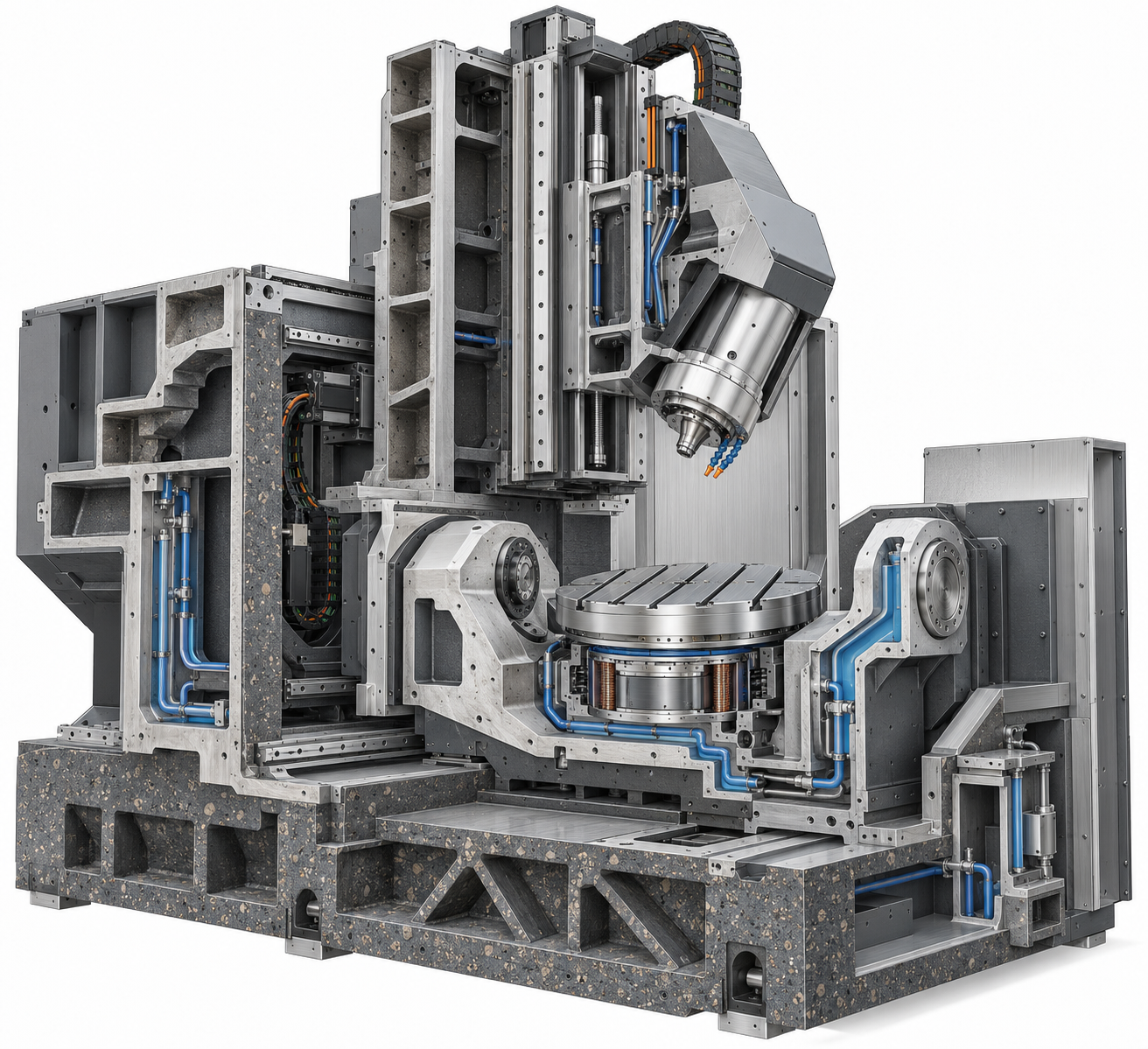
Thermal stability: the most easily underestimated link in the future of machining
Day-night temperature swings in the workshop, heat generated by the spindle and ball screw in operation, and heat carried away by chips will all cause the machine tool structure to slowly deform. The manifestation is not a "sudden out-of-tolerance," but rather the first part passes, the morning passes, and drift begins in the afternoon. Common countermeasures include thermally symmetric structural design, spindle oil cooling/water cooling, hollow ball screw cooling, full-closed-loop feedback from linear encoders, and letting the machine run long enough in a constant-temperature workshop before starting machining. For parts with narrow tolerance bands, the benefits of thermal stability often exceed those few microns of positioning accuracy improvement on paper.
Overall, the evolution of the machine tool itself in these three directions is essentially answering the same question: how to make parts consistently land in the middle of the tolerance band during continuous production, rather than at the edge. Compounding reduces the datum chain, high rigidity supports difficult-to-machine materials, and thermal stability safeguards long-term consistency. The superposition of these three lines forms the basic foundation of the future of machining at the hardware level.
The second main line of the future of machining: AI and adaptive control, first solving trial cutting and reliance on experience
What happens when you put a difficult-to-machine material part that has never been made before onto a machine tool? The process in most workshops is: check the handbook, dig up old programs, ask the veteran master, and then take a piece of stock to trial cut. If the first cut sounds wrong, reduce the feed; if the second cut has chip evacuation blockage, change the insert; if the third cut is off in dimension, compensate. After a long struggle, it finally runs smoothly. This process is nothing to be ashamed of; it is the crystallization of decades of experience. But it has two weaknesses—if you change the person, the machine tool, or the batch of material, the experience may not necessarily be reproducible; trial cutting itself consumes labor hours, tools, and material.
The so-called entry of AI and adaptive control into machine tools is essentially meant to solve these two things. It is not about making the machine tool able to work on its own, but rather compressing the "trial-and-error" process from dozens of times to a few times, and turning reliance on an individual's feel into reusable strategies. This section only discusses what it actually does in the process, what the prerequisites are, and what it cannot replace.
Adaptive feed: letting the machine adjust speed on its own by listening to cutting force
Traditional CNC follows the feed hard-coded in the program. When encountering uneven allowance, fluctuations in material hardness, or tool wear, the load rises and falls unpredictably: at best chatter and a shiny surface, at worst edge chipping and tool breakage. What adaptive control does is very direct—collect spindle power or cutting force signals in real time and dynamically adjust the feed override, keeping the cutting load stable within a set band. Increase efficiency during roughing, preserve surface quality during finishing.
Its value is most obvious with difficult-to-machine materials: titanium alloys, superalloys, and hardened steel, where tool life is extremely sensitive to load. A common industry practice is to first set the load upper limit conservatively, run a few parts to observe the tool wear trend, and then gradually open it up. There are no universal parameters here—the load threshold must be calibrated according to the tool, material, and rigidity, and you cannot simply copy someone else's program.
Monitoring and prediction: tool breakage, chatter, and tool life each handle one segment
Beyond adaptive control, what truly saves the day in the workshop are often a few plain monitoring functions: tool breakage monitoring immediately emergency-stops when the tool breaks, avoiding continuous scrapping; chatter monitoring identifies abnormal vibration and prompts reducing depth of cut or changing spindle speed; tool life management reminds for tool changes based on cumulative cutting time or load integral. These do not require large models; they can be done with vibration, acoustic emission, and spindle current sensors plus rules.
Further "prediction" only then begins to use learning: correlating historical machining data with tool wear amounts to predict how many more parts a certain tool position can machine. The prerequisite is that the data is clean enough and plentiful enough. For small-batch orders with only a dozen or so samples, prediction is often less reliable than an experienced team leader.
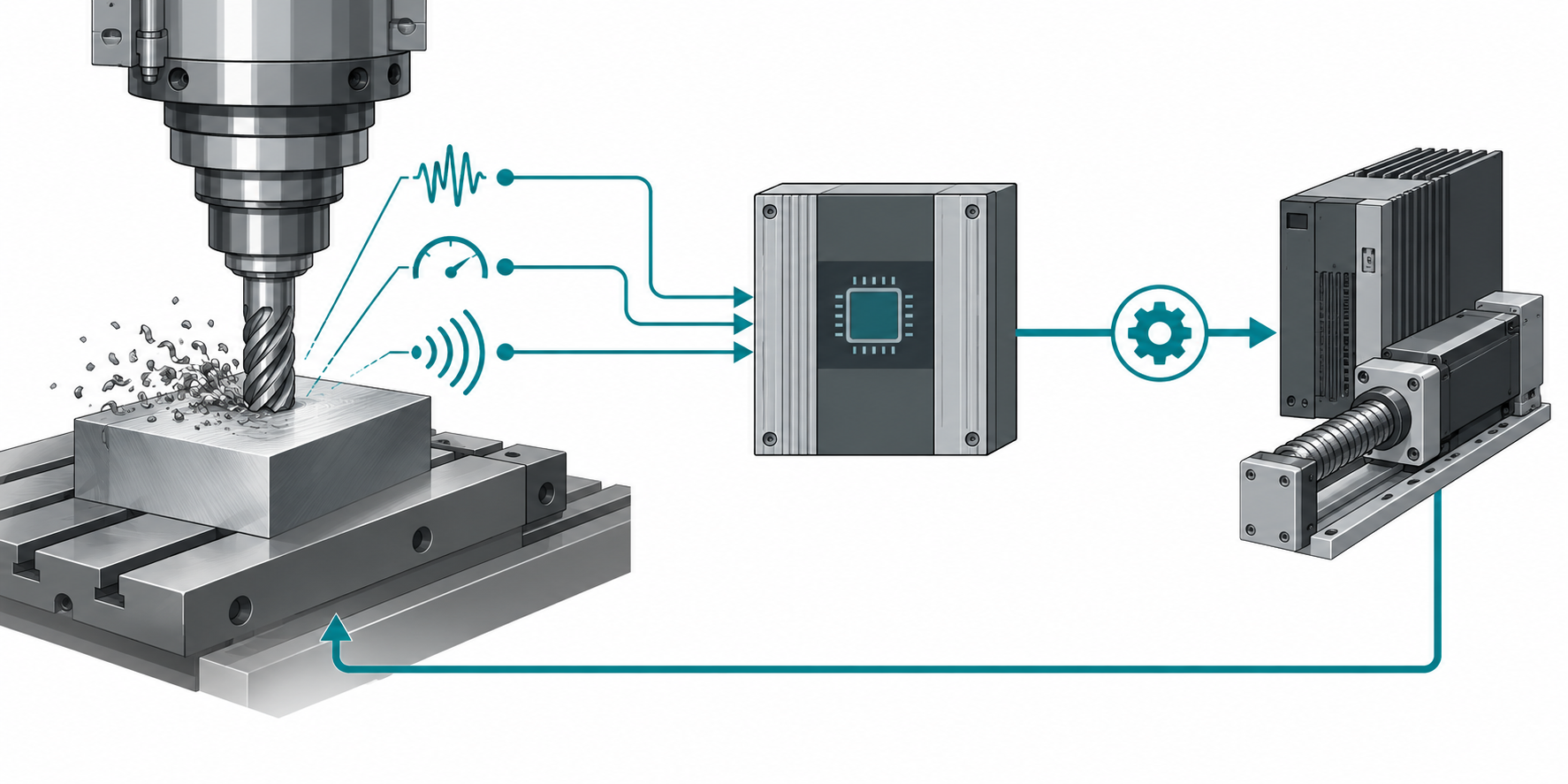
On-machine measurement closed loop and CAM parameter recommendations: turning the veteran master's "compensation cut" into data
Dimensional drift during machining is normal—thermal deformation, tool wear, and material batch differences will all cause dimensions to slowly deviate. On-machine probing can measure key dimensions within one process and feed the deviation back to the program for automatic compensation. This is much faster than stopping the machine, removing the part, sending it to a CMM, reclamping, and machining again, and it also avoids datum loss caused by secondary clamping.
The change on the CAM side is quieter: in the past, programming relied on the master guessing spindle speed and feed, but now software is beginning to recommend initial parameters based on material libraries, tool libraries, and historical machining records. What it recommends is a starting point, not the endpoint—the first part still has to be measured, and gauges still have to be used; it just turns "starting trial from zero" into "fine-tuning from a reasonable value."
Data prerequisite: if signals cannot be collected, it is only a concept
Whether this entire set of things can be implemented depends not on the algorithm, but on whether the machine tool can collect physical signals such as vibration, load, and temperature, and whether the signals can be correlated with program blocks, tools, and workpieces. Old machine tools have no sensor interfaces and no open data channels, so no matter how good the model is, there is no way to start. Therefore, when discussing AI machining, the first question to ask is: where is this machine tool's data output? At what frequency can it collect? Can it be associated by program block?
The third main line of machining's future: from subtractive to "subtractive + additive + composite" in parallel
Additive forms the shape first, then the machine tool delivers the precision
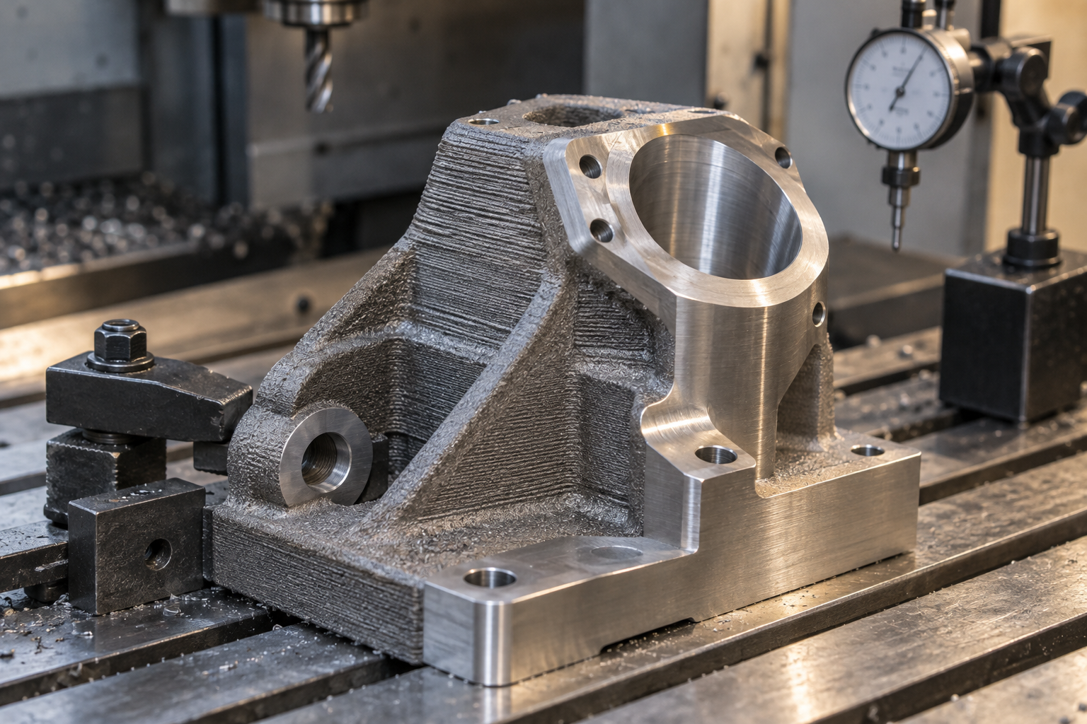
Composites and vacuum casting: the middle ground for small batches
Choosing a process by batch size: a practical order of judgment
The part not visible on the drawing: inspection, in-machine measurement, and traceability
The earlier discussion of the machine tool itself, AI control, and multi-process parallelism all addresses "how to produce the dimensions." But what really determines whether a batch of parts can be delivered is often the half that cannot be seen on the drawing: how to know it was made correctly, and whether the next batch can still be made correctly. Machine tool accuracy only guarantees "a chance to achieve it"; inspection gives the conclusion. This is where the most easily overlooked link in machining's future lies.
A common scenario: the first article passes full-dimensional CMM inspection, and production is signed off; by the inspection tour on the third day, the position tolerance of a certain mating hole is approaching the upper limit. The cause is thermal elongation of the tool holder, gradual accumulation of fixture marks, or the workshop temperature difference between the night shift and the day shift. This kind of drift cannot be seen by the machine tool itself and can only be caught by inspection data.
First article, patrol inspection, and final inspection: what each inspection method handles
A plain division of labor: coordinate measuring machines (CMM) handle geometric tolerances—position, coaxiality, profile, and other items that cannot be measured with calipers; vision measuring machines handle small parts, thin-walled parts, and batch profile dimensions, and are fast; roughness testers handle Ra/Rz, measured only when specified on the drawing, but they are indispensable for sealing surfaces and sliding surfaces; 3D scanning is better suited for reverse modeling and overall first-article comparison, and can quickly show "where it bulged and where it sank," but it measures surface profile deviation and is not equivalent to replacing CMM dimensional judgment.
The measuring instrument itself also has uncertainty. A common industry reference: the indication error of a CMM for small and medium-sized parts is often on the order of sub-micron to a few microns, but this depends on temperature, probe, and calibration status—if the part's tolerance band itself is only ±0.01 mm and the measuring instrument error takes up thirty percent, judgment becomes very risky. Therefore, tight-tolerance parts often require constant-temperature measurement, or the use of gauges/go-no-go gauges for quick on-site judgment.
On-machine measurement: one less setup, one less lost datum
The greatest value of an on-machine probe (a touch-trigger probe mounted on the machine spindle) is not "saving a CMM," but not losing the datum. A part completes roughing → semi-finishing → on-machine measurement of actual stock allowance → tool offset compensation → finishing within a single setup, avoiding the error amplifier of "take it off to measure, then put it back and re-establish the datum." The benefits are especially pronounced for thin-walled parts, irregular shapes, and housings that need to be flipped.
But be clear about its boundaries: on-machine measurement is affected by machine positioning accuracy and temperature, making it suitable for process judgment and tool offset feedback, while final acceptance typically still requires an offline CMM or dedicated gauges. Treating an on-machine probe as a final inspection method easily leaves room for dispute.
SPC and batch traceability: making "machine tool manufacturing, machining the future" more than just a matter of one piece of equipment
A passing first article does not mean the process is under control. Applying SPC to critical dimensions—sampling by batch or time point, recording the mean and range, and watching whether the trend is drifting—is what allows adjustment before out-of-tolerance occurs, rather than waiting for customer complaints. Traceability requires that which material batch, which machine, which program, which operator, and which tool change can all be tied to a specific part serial number. These two things sound like management, but they are actually the data foundation for process stability, and also the part of "machining the future" that is hardest for AI to replace—because it depends on whether the shop floor is willing to record things carefully.
Inspection cost is forced out by the drawing
There is a direct relationship: the tighter the tolerance, the higher the proportion of inspection cost. A drawing with strict tolerances on all dimensions often means full CMM inspection, temperature control, dedicated gauges, and even piece-by-piece inspection. By marking critical dimensions (fits, seals, motion pairs) tightly and relaxing non-critical dimensions (exposed contours, non-mating hole positions), inspection resources can be concentrated where they truly affect function. This is the most cost-effective step in the DFM stage—no need to change the machine, only the dimensioning habits.
So when looking at a drawing, you can ask yourself: which dimensions are functional dimensions, and which are just "marked along the way"? If all tolerances on a drawing are equally tight, it usually means the design side has not yet made trade-offs. Before sending such a drawing for CNC machining, having the process side give a feasibility assessment can save a lot of back-and-forth in advance.
What it means for those who make parts: criteria for choosing a process based on batch size and tolerance
The three main threads above—the machine tool itself, AI and adaptive control, and subtractive and additive manufacturing in parallel—all sound far removed from a specific drawing. When it actually comes time to place an order, there is only one question: which route should this part take. The following sequence of judgment does not aim to cover every situation, but it can converge most selection debates onto a few verifiable points.
First define critical dimensions and datums, then discuss machine type
The order cannot be reversed. If you choose the machine first and then think about tolerances, the result is often "the machine has enough capability, but the datum was defined incorrectly." The correct approach is: circle on the drawing the dimensions that truly must be guaranteed (mating surfaces, hole positions, runout, flatness), determine which datum they share; then see whether these datums can all be machined in a single setup. For parts with inconsistent datums that require multiple setups, switching to a five-axis mill-turn machine is often more effective than improving single-machine accuracy, because what is reduced is the error from one setup, not the positioning error of the machine itself.
Cost-driven tolerancing: relaxing non-critical dimensions is the fastest way to save money
On the same drawing, relaxing non-mating contour dimensions from ±0.05 mm to ±0.2 mm usually does not change function, but may allow a single pass to complete the roughing stage, reducing finishing time and inspection labor. The common situation in the industry is that the dimensions truly requiring tight control account for only 10% to 20% of the entire drawing. If the whole drawing is marked tightly, the supplier will either quote to the tight standard or reserve a large amount of rework margin in the quote. Therefore, when reviewing a drawing, it is worth asking item by item: is this tolerance required for assembly, or is it marked out of habit?
Batch size determines the process, not the other way around
Batch size is the watershed. From a few pieces to a few dozen, CNC machining or 3D printing is the most direct way to make prototypes and validate structure; for hundreds of pieces, with a simple structure and a desire for materials close to production, vacuum casting can provide samples with an appearance close to injection molding; beyond that, with fixed material and sensitivity to per-piece cost, the amortization effect of injection molding molds only then holds. Sheet metal and machining often divide work on the same equipment housing: the outer shell uses bending and welding, while the internal mounting plate uses CNC milling. Lay out the three coordinates of batch size, material, and structural complexity, and the process choice is basically 90% determined.
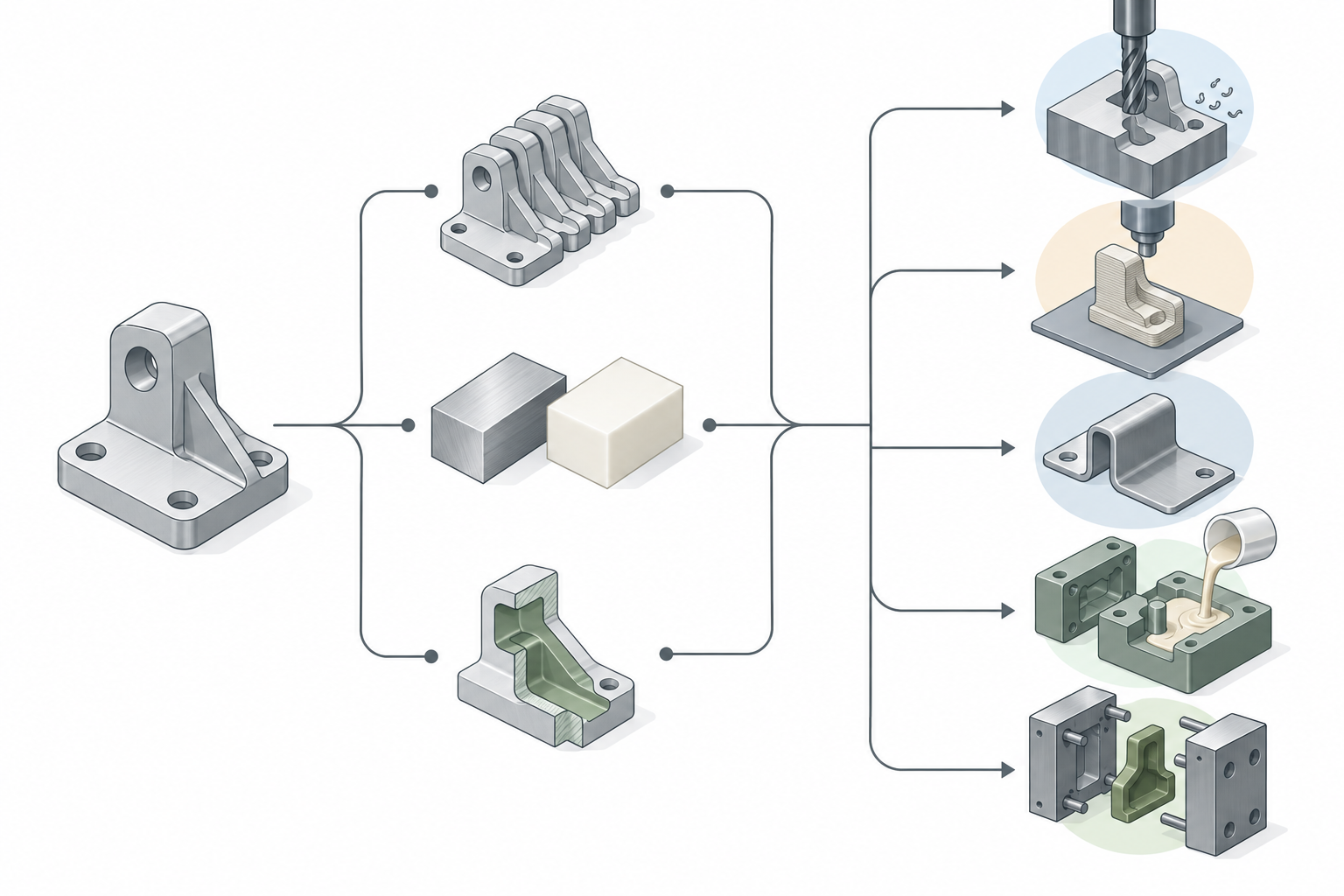
Put fixturing and inspection into the decision sequence
The complete decision sequence is: define critical dimensions and datums → choose the fixturing approach → choose the machine type → define the inspection method. The fixturing approach is often skipped, but it directly determines whether the drawing requirements can be met: a thin-wall part may spring back after being clamped in a vise and released, so soft jaws, vacuum holding, or a dedicated fixture need to be considered; when an irregular part has no reliable support surface, adding an auxiliary process boss is more practical than increasing cutting parameters. The inspection method must also be defined in advance: CMM for critical dimensions, vision measuring system for contours, roughness tester to verify mating surfaces. Which dimensions go on the CMM and which are only sampled with conventional gauges should be aligned with the supplier before quoting. All the above values are common industry references; actual achievable capability must be confirmed item by item according to the drawing, material, and rigidity.
How to judge whether a supplier can keep up with the future of machining
The previous sections covered where machine tool manufacturing is heading and which main lines are driving the future of machining. When it comes down to a specific project, the question becomes very short: if this drawing is given to someone, can they get it right the first time and keep it stable in production? An equipment list can only answer part of it; the rest has to be asked.
Don't start by asking "how many five-axis machines do you have." A few different questions are more effective: can they cut difficult-to-machine materials, can they still finish-machine after heat treatment, what do they use to measure critical dimensions, and how is the process controlled beyond the first article? The answers to these questions say more about how close a supplier is to the future of machining than equipment model numbers do.
Beyond the equipment list, ask about process boundaries first
Ask about specific working conditions, not general capabilities. For example, how much titanium alloy or hardened steel needs to be cut, what tooling is used, roughly what range of spindle speed and feed, and whether high-pressure cooling is needed; whether the part needs to be completed in one setup on a mill-turn machine, or whether they are willing to split it into two operations. A supplier who can clearly explain "why this operation is sequenced this way and how the datum is transferred" is usually more reliable than one who only quotes machine brands.
You can also ask about the finishing arrangement after heat treatment. Many parts pass rough machining, but after quenching or aging the dimensions and geometric tolerances change. Whether they can finish-machine again in the hard state and how much stock to leave directly determines whether the job can be taken on. A common industry practice is to leave 0.2–0.5 mm of stock in rough machining and then finish-machine, with specifics confirmed according to the material and deformation conditions; it cannot be generalized.
Inspection fixtures and measurement methods determine the gap between "made it" and "made it stably"
Ask how the first article is inspected, how batches are sampled, and whether critical dimensions have in-machine probes or CMM records. A production line with only calipers and tape measures is fine for general structural parts; once the tolerance band tightens to something like ±0.02 mm, without a CMM, vision measuring system, or roughness tester, it is basically down to luck. 3D scanning is also commonly used for reverse engineering and first-article comparison, especially for troubleshooting freeform surfaces and assembly interference.
Then look at process control. Are parts from the same batch completed on the same machine and with the same fixture set, how is the datum reproduced when changing batches, and is there simple SPC record keeping? The adaptive and in-machine closed-loop concepts discussed in the future of machining are essentially about doing this in more detail; without basic measurement and records, even the smartest system cannot pick it up.
DFM feedback must be specific down to tolerances and fixturing
Good DFM feedback will not just say "this structure is hard to machine." It will point out which tolerance grade is a cost-driving tolerance that can be relaxed; which internal right angle needs a corner-clearing tool or should be changed to a fillet; which thin wall will deform during fixturing and should be stiffened or have the clamping method changed. The more specific this feedback is, the more it shows the other party is taking on the job based on process judgment, rather than passing the drawing along for a quote.
Finally, ask clearly about the interface between low-volume and mass production. The prototype stage may use 3D printing or CNC prototyping, low volume may use vacuum casting or sheet metal, and mass production may switch to injection molding or a dedicated machine—if this path is not connected and every stage requires a new mold or new machine setup, then the flexibility discussed in the future of machining cannot be realized.
Frequently asked questions
The following questions are basically the places where people get stuck most easily after reading the previous content: what exactly is the difference between machine accuracy and part accuracy, whether five-axis and multi-tasking are worth adopting, what AI can currently do in machining, and how to judge whether a supplier can keep up with the pace of the future of machining.
The machine's nominal positioning accuracy is very high, so why are my parts still out of tolerance?
Because positioning accuracy and repeat positioning accuracy describe the machine's capability under controlled conditions, while a part's tolerance band is the combined result of machine error, thermal deformation, fixturing deformation, tool wear, and chip heat. After the spindle and ball screw run continuously and heat up, the day-night temperature difference in the workshop, and the clamping force of a vise or soft jaws can all cause dimensions to drift slowly over several hours. Common industry practice is to leave margin on critical dimensions, arrange rough and finish machining separately, and if necessary measure in-machine before making a tool compensation cut. For your specific part, this must be confirmed item by item according to the drawing, material, and fixturing rigidity; you cannot directly take the numbers in the machine manual as a guarantee for the finished part.
Should all parts go on five-axis or mill-turn machines?
No. The value of five-axis and multi-tasking machines lies mainly in reducing the number of setups, lowering datum transfer errors, and machining complex curved surfaces or difficult-to-cut materials. The trade-offs are more complex programming and tooling, higher machine-hour costs, and higher demands on process engineers. For parts with simple structures, conventional tolerances, and large batch sizes, a three-axis machining center with dedicated fixtures is often more cost-effective. The recommended order of judgment is: first check whether the structure requires completing multiple faces in a single setup, then check whether the material is difficult to cut, and only lastly consider batch size and cost. All values are only common industry references and must be confirmed against the drawings.
What can AI and adaptive control actually do in machining today?
The more practical directions at present are adaptive feed, tool breakage and chatter monitoring, tool life prediction, closed-loop on-machine measurement, and CAM parameter recommendations. Their core role is to shorten the number of trial cuts and turn veteran machinists' experience into reusable strategies. They cannot eliminate first-article confirmation and gauge verification. Moreover, these functions depend on the machine being able to capture signals such as vibration, load, and temperature. When the data foundation is not in place, so-called intelligent machining tends to remain at the conceptual level.
Does the future of machining mean additive manufacturing will replace subtractive machining?
A more accurate way to put it is division of labor. Additive is suitable for complex blanks, conformal cooling channels, and lightweight lattice structures, followed by machining on a machine tool to finish critical mating surfaces; subtractive remains the mainstay for dimensional accuracy and surface quality; for small batches, vacuum casting or duplicate molds from prototypes can serve as a transition; for mass production, it returns to injection molding and dedicated machines. The usual order for selecting a process is batch size, structural complexity, material, critical tolerances, and surface requirements—not which process is newer.
How can you tell whether a supplier can keep up with the future of machining?
Don't just look at the equipment list. You can ask a few specific questions: Can they perform finishing after heat treatment on difficult-to-cut materials? Do they have multi-tasking or reduced-setup solutions? Which dimensions are covered by their gauges and measurement methods? How are first articles and process control handled? Is the DFM feedback specific enough to tolerances, fixturing, and tooling? How is the transition between small-batch and mass production handled? Machine tools are the hardware prerequisite, but what truly determines whether parts can be produced stably is process judgment and a closed inspection loop. It is recommended to confirm the specific capability scope item by item against the part drawings.
Key takeaways
- The progress of machine tool manufacturing must ultimately be translated into tolerance bands that can be reliably delivered on part drawings; machine tool precision does not equal part precision—fixturing, tooling, thermal deformation, and inspection each account for a share.
- The three main lines of the machining future: the machine tool's own precision and thermal stability, AI and adaptive control on the process side, and turn-mill multi-tasking and parallel additive-subtractive processes on the operations side.
- The realistic place of AI in CNC machining is "shortening trial cuts and reliance on experience," not eliminating first articles and gauges; parameters still need to be validated according to material, tooling, and rigidity.
- When selecting a process, first look at reachability and cost-driving tolerances: what can be made with turn-mill multi-tasking or fewer setups is often more cost-effective than pursuing the ultimate precision of a single machine.
- To judge how genuine a supplier's "machining future" is, see whether it can explain machine tool capability, gauges, and process judgment together, rather than just looking at the equipment list.



