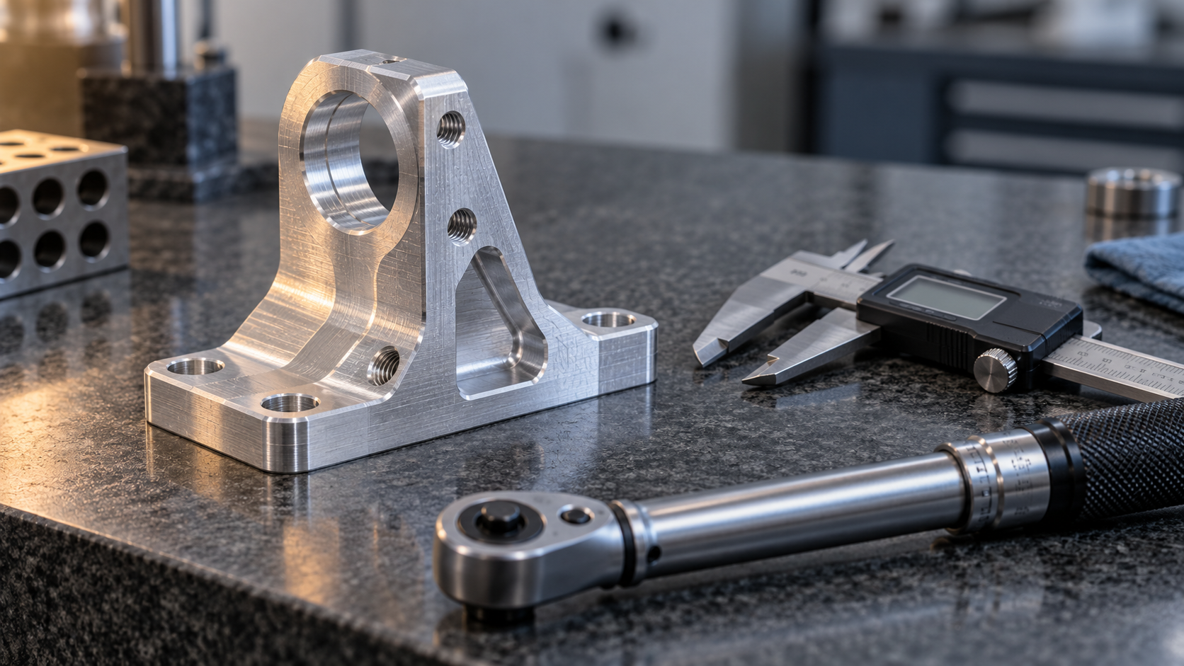
Machining and assembly are one chain, not two operations
Tolerances are not better the tighter they are: the real relationship between machining cost and achievability
The drawing says ±0.02, and the senior machinist in the workshop takes one look and doubles the quote. This is not arbitrary price gouging, but rather that once a tolerance crosses a certain line, the machining method shifts from "a single pass on a standard mill" to "tool changes, cooling, slow feed, and full CMM inspection." In the machining and assembly chain, tolerance is the first place where cost and process are bound together.
Narrow the tolerance band by one grade, and the process may need to be changed entirely
With the same outer profile, ordinary CNC milling achieving the ±0.05 mm range is routine; to hold steady in the ±0.02 mm range, you often need to separate finish milling and semi-finish milling, reduce cutting parameters, and keep a close eye on tool wear. Going further to ±0.01 mm, grinding or high-precision machine tools are the reliable route, and it is not simply a matter of "the machine tool being accurate enough"—fixture rigidity, ambient temperature, and measurement methods all eat into that remaining margin. A common industry practice is: general milling in the ±0.05 mm range, finish milling in the ±0.02 mm range, and grinding down to the ±0.005 mm range, but these are only judgment references; whether a specific feature can be achieved must be confirmed against the drawing and the actual fixturing plan.
The cost jump is not because machining time increases linearly, but because the number of operations, inspection methods, and scrap risk all rise at the same time. A ±0.05 hole can be drilled and then reamed; a ±0.01 hole may need boring, measuring, and reworking. Every extra step accumulates labor hours and risk.
Which features are inherently expensive, and which can be relaxed
The same tolerance is much harder to achieve depending on the feature it falls on. Deep holes, thin walls, slender shafts, and small tolerances on large flat surfaces all fall into the category of "looks simple, hard to make." Deep holes make chip evacuation difficult, the tool overhang is long, and the tool easily deflects; thin walls deform as soon as they are clamped, and when released the workpiece springs back and the dimensions are off again. Conversely, locating pin holes and bearing seats used for fits must be strict where strictness is required, because these dimensions directly determine whether assembly can press in.
- Where strictness is required: fit diameters, locating holes, bearing seats, sealing surfaces—if these dimensions are out of tolerance, assembly will have problems.
- Where it can be relaxed: non-fitting outer shapes, clearance grooves, internal fillets, and contours that do not contact other parts.
- Where tightening is easily added by mistake: writing the intuition that something "looks like it needs precision" as ±0.01, when actual assembly does not need it at all.
The chain reaction of tolerances, measurement, and assembly
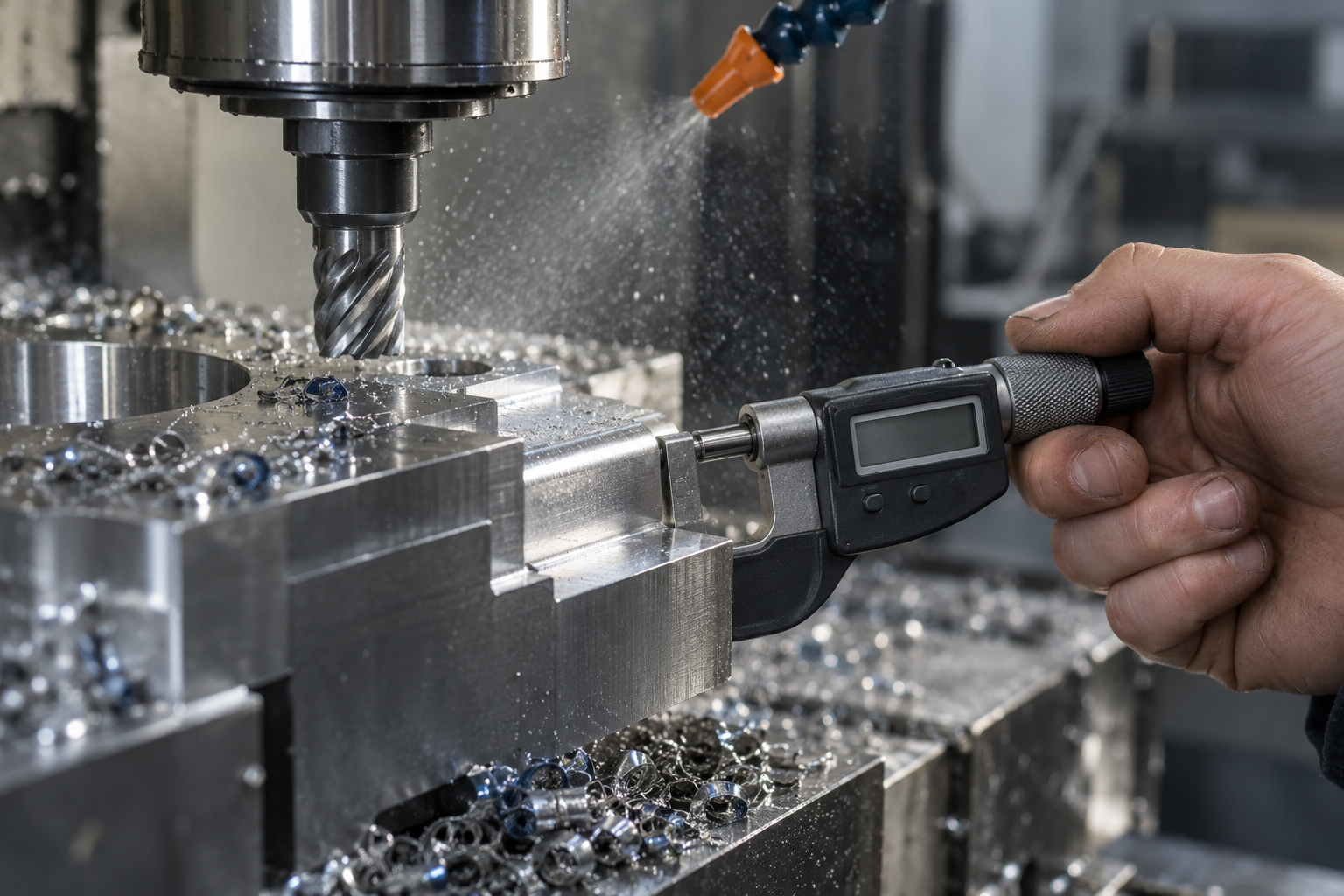
Tolerances also involve measurement. If the measuring instrument itself has a resolution of only 0.02 mm, using it to measure a ±0.01 dimension makes the reading itself unreliable. In the industry, the uncertainty of the measuring instrument is generally required to be controlled to 1/10 to 1/5 of the tolerance band; for example, for a ±0.02 tolerance, it is best to use a micrometer that can read to the 0.002 mm range or a higher-precision gauge. If this step is not set up well, the preceding machining precision is wasted.
What is more hidden is the assembly end. Two parts may each be within tolerance, but when assembled together there may be too much clearance or interference. This is the problem of tolerance allocation—it is not that making every part to the tightest tolerance will ensure good assembly, but rather that the assembly clearance must be reasonably distributed among the parts at the design stage. When tolerance allocation is done correctly, machining cost and assembly difficulty both decrease.
To judge whether a tolerance should be strict, you can ask three questions: Does this dimension contact other parts? If it is out of tolerance, will it fail to assemble or merely look bad? Can the existing measuring instruments measure it reliably? Running through these three questions will usually filter out a batch of unnecessarily tight tolerance requirements. When a specific evaluation is needed, the drawing can be given to the machining party for a manufacturability review, and then the tolerances can be decided.
Datums and fixturing: errors arise before the workpiece is even cut
Many dimensional problems, when traced to the end, are not because the tool is inadequate or the machine tool is not accurate enough, but because the datum and fixturing were not arranged well. In the chain of machining and assembly, fixturing is the first step that "lands" the ideal geometry on the drawing—the way it lands determines the starting point of all subsequent errors. Before the workpiece is cut, it has actually already been forced to accept a set of geometric constraints through locating and clamping. If this set of constraints is inconsistent with the design datum, errors begin to accumulate from here.
Datum unification: drawing datum, process datum, and measurement datum should be on the same line as much as possible
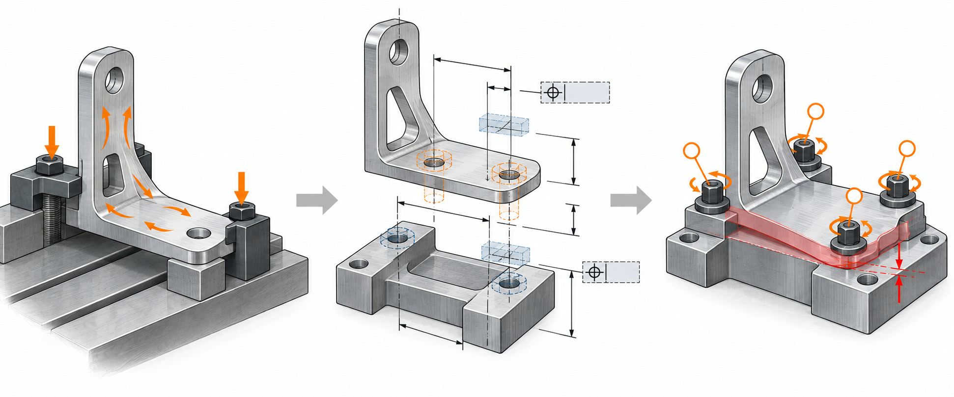
The principle of datum unification is simple to state: the design datum, process datum, and measurement datum should coincide as much as possible. In practice, the problem often lies in the datum transfer chain. For example, for a bracket, the design specifies the bottom surface A as the datum and requires the position of the upper hole relative to A. If the first operation uses the blank side surface for locating to machine bottom surface A, and the second operation then uses A for locating to drill the hole, the datum chain is "blank side surface → A → hole." The form error of the blank side surface will be amplified or translated through A and transferred to the final position of the hole. One more conversion means one more chance for error accumulation.
Therefore, in process planning, a reliable datum surface is usually machined first, and subsequent operations use it as much as possible. If the part has dimensional requirements in multiple directions, a combined datum such as one surface and two holes can be used to constrain all six degrees of freedom and reduce random errors caused by repeated alignment. In machining and assembly, many assembly interference problems, when traced back, are found to have originated from the datum chain already being off during the machining stage.
Clamping force and cutting force: thin-walled parts spring back after clamping is released
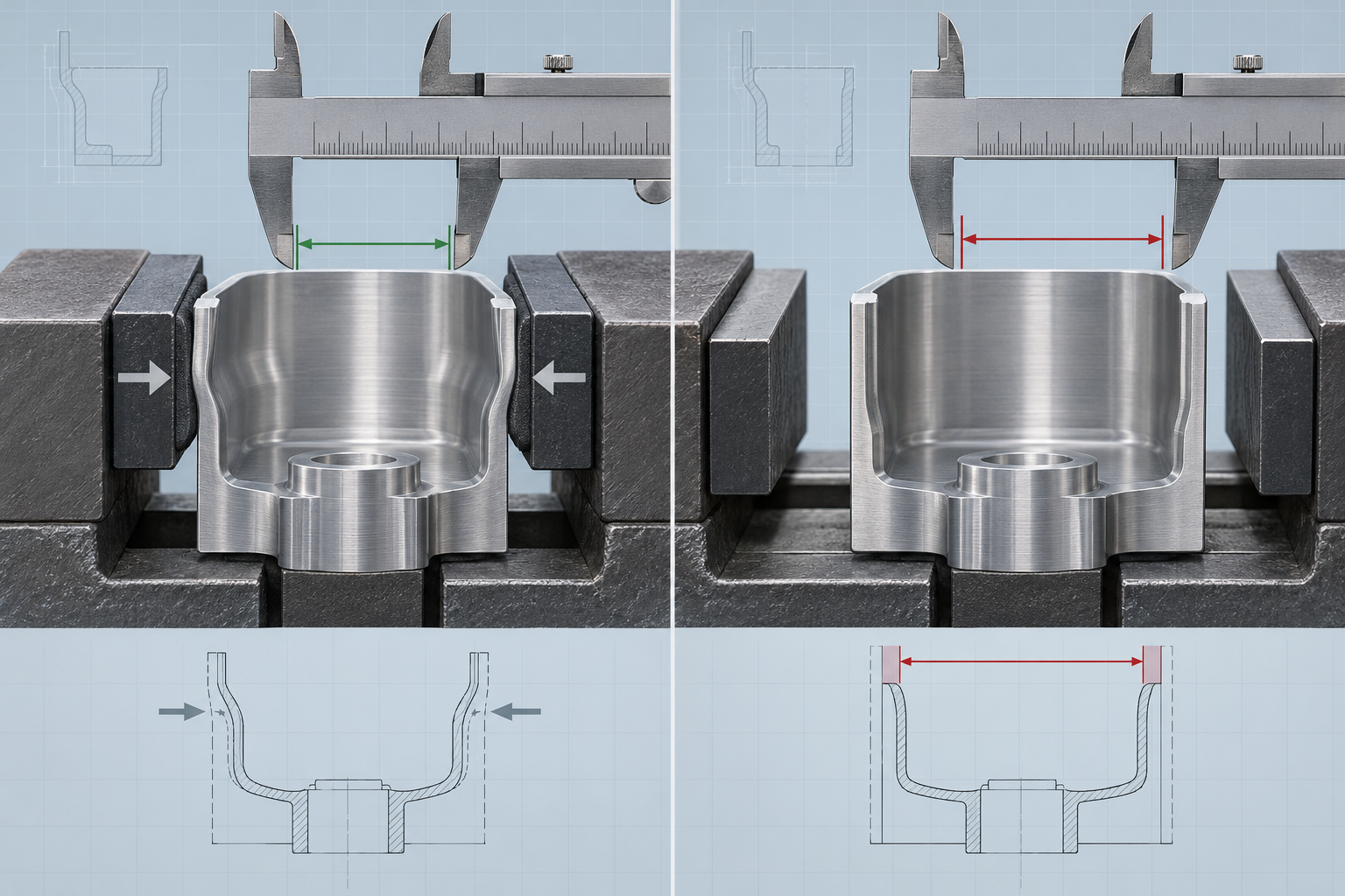
Thin-walled parts are the most typical. When clamped by a three-jaw chuck or vise, the workpiece is compressed and deformed, and the dimensions measured at that time are acceptable; when the fixture is released, elastic recovery changes the dimensions and roundness again. This type of problem cannot be completely solved by simply "clamping more lightly," because if the clamping force is too small, the workpiece may move under the cutting force. Common approaches are: add auxiliary supports, use soft jaws or dedicated fixtures to distribute the clamping force, arrange clamping points at positions with better rigidity, and separate rough and finish machining so that finish machining is completed under lower clamping force.
Slender shafts are another example. During turning, the workpiece itself lacks rigidity, and the cutting force bends it, resulting in tool deflection in the middle and a barrel-shaped machined part. Using a follower rest or steady rest to provide support near the cutting point is a conventional practice. But the support itself also introduces new contact errors and requires adjustment.
Reduce the number of setups: whatever can be done in one setup, don't split into two
Every additional setup means one more alignment error, one more clamping deformation, and one more stretch of auxiliary time. Being able to complete machining of multiple faces in a single setup on one machine is usually more stable than multiple setups. This is also one of the reasons five-axis and turn-mill machines are widely used—not for showing off, but to minimize datum transfers. Of course, a single setup also has costs: fixtures may be more complex, tool accessibility is limited, and chip evacuation and cooling are harder. In process planning you have to weigh the trade-offs, not blindly pursue "doing it all in one go."
For parts that genuinely require multiple setups, a practical approach is to keep a unified process datum, such as pre-machining a process boss or process hole on the blank, and locating on it for every subsequent setup. This way the positioning error direction is consistent each time and won't stack up in a random manner. After the fixturing plan is determined, it's best to actually measure the springback after release on the first article—even just recording the trend is better than judging by feel. The specific springback amount varies with material, wall thickness, and clamping method, and needs to be confirmed against the drawing and actual working conditions; there is no fixed value that can be directly applied.
From blank to finished part: several key trade-offs in machining sequence
The same drawing, given to two different shops, may produce parts that both pass inspection, but the scrap rate, lead time, and smoothness of subsequent assembly can differ greatly. The difference is often not in the machine tool, but in the operation sequence. Many troubles in machining and assembly are planted by the sequence: which face to mill first, when to heat treat, how long after rough machining before finish machining—these look like internal shop arrangements, but they directly determine whether it will fit in the end.
Separating rough and finish machining is the most basic rule in sequencing. The goal of rough machining is not dimensions, but removing most of the stock and creating the shape. At this stage cutting forces are large, heat generation is high, tool deflection is pronounced, and internal residual stresses in the workpiece redistribute as material is removed. If rough and finish are done in one pass, the finish dimensions are measured on a workpiece that is still deforming; once the part cools and stresses release, the dimensions drift. A common practice is to leave 0.3–1 mm stock for rough machining (specifics depend on material and part rigidity, confirm against drawing and process), then finish machine. Thin-walled parts and long overhang parts leave more.
Stress relief: let deformation happen before finish machining
Whether to relieve stress after rough machining depends on the material, stock size, and final tolerance. Castings, forgings, and weldments carry casting or welding stresses themselves, and warp as soon as rough machining begins; such parts often undergo stress-relief annealing after rough machining, then finish machining. Aluminum alloys, some stainless steels, and hardened steels also deform noticeably when a large amount of material is removed in rough machining. Natural aging (resting for days to weeks) and artificial aging (stress-relief annealing) are two paths; the former is slow and low-cost, the latter is fast and requires heat treatment coordination. Which to choose depends on lead time and tolerance requirements—tight tolerances and large batches usually favor artificial aging. There is no universal answer here; it must be judged according to the specific part.
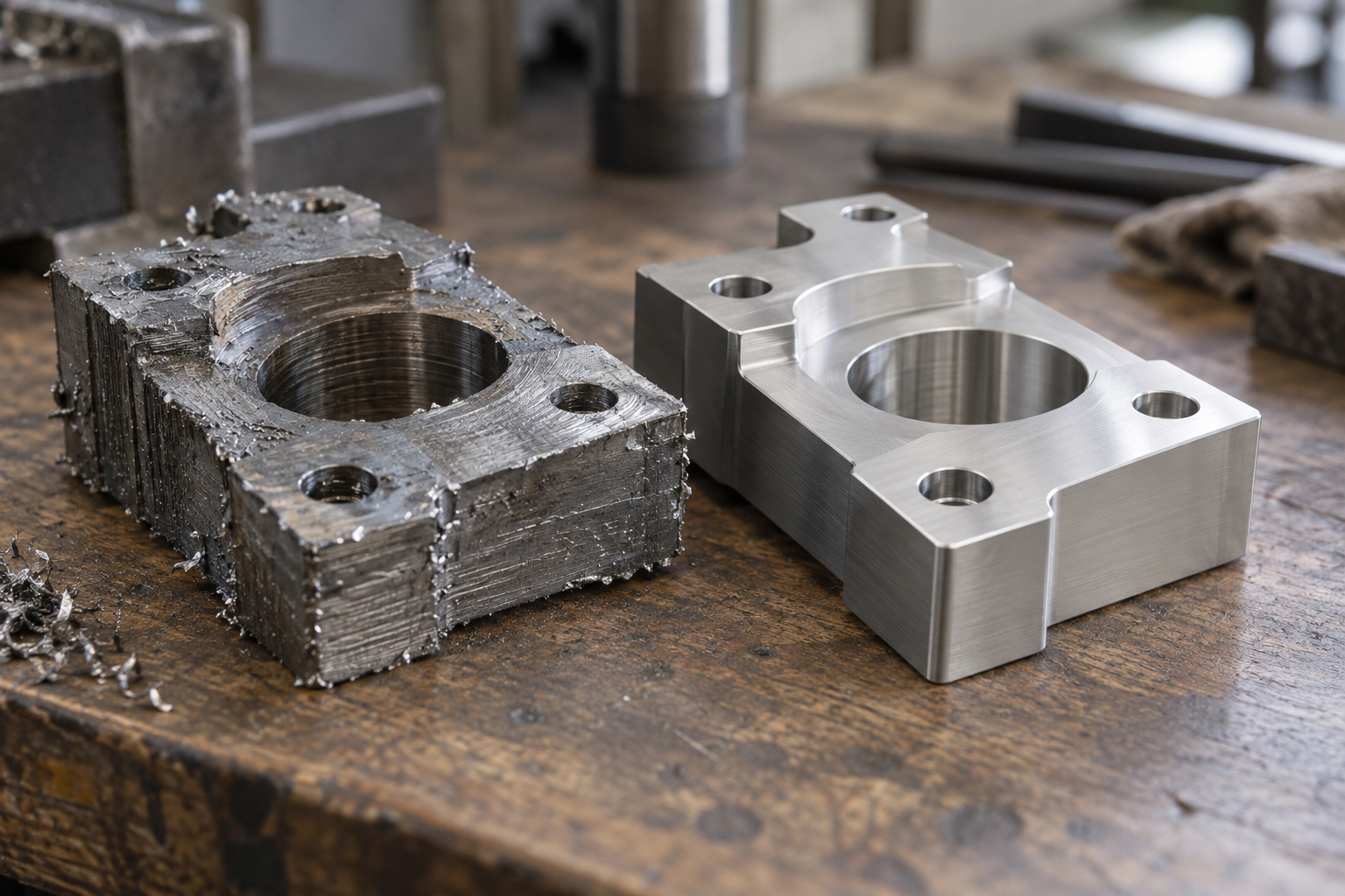
Machining the datum face first is another easily overlooked rule. Subsequent operations all rely on the datum for positioning; if the datum face itself is a blank surface and uneven, every subsequent step is positioned off. The correct sequence is to first machine a reliable datum face (or datum hole), then use it to locate and machine other faces, forming a unified datum transfer chain. Once the datum is messed up, even dimensionally acceptable parts may not assemble, because the positional relationships are wrong.
Where heat treatment is placed determines whether the part will still deform
For parts requiring quenching or tempering, heat treatment brings deformation and dimensional changes, so it cannot be casually inserted after finish machining. A common arrangement is: rough machining → heat treatment → finish machining. Placing heat treatment before finish machining lets deformation happen first, then finish machining corrects it; placing it after finish machining means quenching deformation will destroy all the dimensions and positions already achieved. Some parts also require grinding or lapping after quenching, so allowance for these finishing operations must be left after heat treatment.
The number of setups is likewise affected by sequence. Every additional setup adds one more accumulation of positioning error. Arranging faces that can be completed in one setup together as much as possible, reducing flipping and re-alignment, is worth weighing during sequencing. The cost is sometimes longer tool paths or the need for special fixtures; whether it's worth it depends on whether the accumulated error is already approaching the tolerance band. There is no unified formula for such judgments; they usually must be determined by combining part features and the shop's actual capabilities.
Inspection is not the last step: how in-process inspection controls dimensions
First-article inspection: what it confirms is process capability, not a single part
CMM, calipers, micrometers, gauges: it's not about high versus low precision, it's about different roles
- Calipers/micrometers: measure the dimension itself, such as outer diameter, thickness, and groove width. Fast, but they cannot measure geometric tolerances, and they struggle to reflect datum relationships.
- CMM (coordinate measuring machine): measures spatial relationships and composite tolerances, suitable for first articles, final inspection, and dispute arbitration.
- Dedicated gauges (plug gauges, ring gauges, position gauges): compress a complex judgment into a single "go/no-go" action, suitable for fast pass/fail checks on high-volume shop floors.
- 3D scanning: suitable for freeform surfaces, cast blanks, reverse comparison, and situations where you need to see the overall deviation distribution rather than a single-point value.
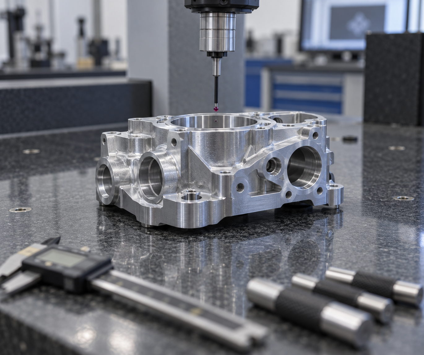
Measuring instruments themselves have uncertainty, and selection must match the tolerance band
Assembly stage: whether parts can fit together must be thought through during machining
The easiest blame for assembly to bear is "all part dimensions are within tolerance, but they won't fit." This type of problem is very typical in the chain of machining and assembly: the machining side inspects every part against the drawing and all pass, but at the assembly bench, holes don't line up with holes, faces don't mate with faces, and shafts won't press into seats. The problem is not that someone did something wrong, but that assembly interference was planted at the drawing stage, and machining merely cashes it out.
So assembly should not be treated as the passive receiving end of machining. It is a stage where difficulty can be actively reduced at the design stage—through tolerance allocation, structural design, and fit selection, making "it will fit" a high-probability event rather than relying on on-site fitting by a bench worker.
Clearance, transition, interference: the choice of fit determines the assembly method
Fit relationships are not abstract concepts; they directly determine what tools are used on site and how much time is spent:
- Clearance fit: the hole is larger than the shaft, and it can be pushed in by hand or lightly tapped with a rubber mallet. Assembly is the easiest, but it places requirements on coaxiality and position tolerance; the larger the clearance, the more easily it wobbles, and positioning accuracy must be ensured by other structures (pins, shoulders, end faces).
- Transition fit: there may be slight clearance or slight interference, and assembly often requires light tapping with a copper bar or pressing in with a press. It demands both positioning accuracy and a certain degree of fastening, making it a common choice for many bearing seats and locating pins.
- Interference fit: the shaft is larger than the hole, and assembly relies on press-fitting or temperature differential methods (heating the hole part or cooling the shaft part). It has strong torque transmission capability, but press-fit force, press-in speed, and mating surface roughness all affect whether the final result is cracking or galling.
A common judgment in the industry is: if a clearance fit can be chosen, do not easily go to an interference fit unless force transmission or positioning truly needs to rely on the fit. The assembly risk of an interference fit is often higher than designers estimate—if the press-fit force is calculated inaccurately, thin-walled parts will deform first.
Fitting and selective assembly: two kinds of "remedy" logic on the assembly floor
When the tolerance chain cannot guarantee that assembly will pass the first time, the assembly side usually has two ways to handle it. One is fitting: leave an allowance in one place, then grind, scrape, or file it to the proper size on site; precision is high, but it depends on craftsmanship and is not suitable for batch production. The other is selective assembly: classify parts by actual size, match large shafts with large holes and small shafts with small holes, and "create" the fit by grouping. Selective assembly can loosen the tolerance of individual parts, at the cost of increased work in measurement, grading, and inventory management.
Neither of these approaches should be an after-the-fact remedy; they should be thought through during process design: which fits must be guaranteed by machining, which may be allowed to leave fitting allowance, and how many grades are needed to raise the pass rate.
Adjustable structures: turn "it won't go in" into "it can be adjusted back"
A more economical approach than tightening tolerances is sometimes to design an adjustable link: slotted holes, adjustable shims, threaded fine adjustment, or elongated holes with eccentric sleeves. Its logic is to shift the dimensional precision requirement from "every part must be accurate" to "it can be compensated during assembly." The cost is a slightly more complex structure and possibly a few more parts, but the assembly tolerance it buys is often worthwhile when batch sizes are not large and the tolerance chain is long.
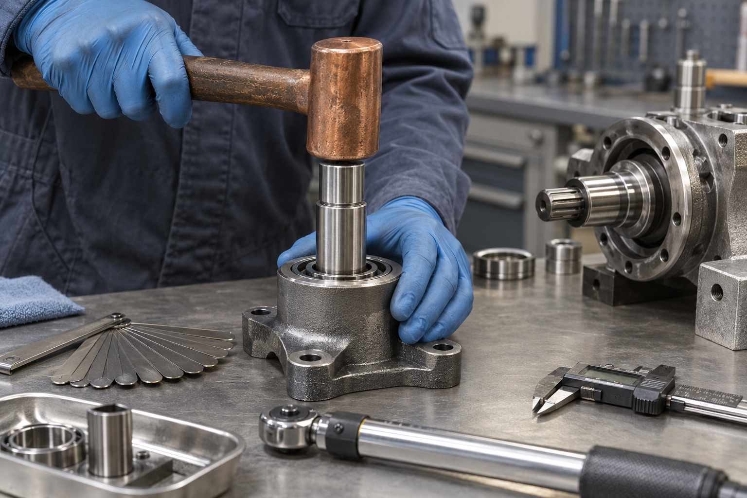
Troubleshooting assembly interference also has an order: first check whether the datums are unified, then check whether the tolerance chain has accumulated out-of-tolerance, and only then suspect the dimensions of individual parts. Many times, the problem lies in non-coincident datums—design datums, process datums, and assembly datums each speak a different language; parts pass inspection individually, but clash when put together.
Writing assembly requirements into the drawing in advance is the lowest-cost step: mark the fit nature at key mating points, leave tool space in the assembly direction, and leave an adjustable link at the end of the tolerance chain. When the machining side sees this information, fixturing and inspection will adjust accordingly. To apply this set of fit judgments to specific parts, you can first run the drawing and assembly requirements through together with AI chat quoting.
Assembly process documents and on-site execution: torque, sequence, and error-proofing
After parts are machined, pass inspection, and are sent to the assembly station, many people think what remains is "screw-tightening work." But the real difficulty on the assembly floor is not speed of hand; it is three things: how much torque to apply, in what sequence to tighten, and how to make sure workers cannot assemble it wrong without having to think. If these three things remain only in the master's head, problems immediately appear when a different person or a different batch of parts comes along. The role of assembly process documents is to turn these judgments from experience into executable on-site constraints.
What really needs to be written clearly on an assembly process card
A workable assembly process card is not mainly about listing parts; its core is to nail down several error-prone points: fit nature (clearance, transition, or interference, and whether heating/press-fitting is required), tightening parameters (torque value or torque-angle method, and whether stepwise tightening is required), tightening sequence (diagonal, star, or from the middle outward), lubrication and bonding requirements (threadlocker type, application location, curing time), and cleaning and protection (whether foreign object control requirements exist). Once these parameters are missing, assembly quality depends entirely on individual feel, and batch-to-batch drift is inevitable.
For multi-bolt connections—such as flanges, end caps, and housing mating surfaces—the tightening sequence often determines the final state even more than the torque value. The purpose of stepwise diagonal tightening (for example, first 30% torque, then 70%, and finally the target value) is to make the mating surface seat evenly and avoid one side being crushed first while the other side lifts. If the sequence is wrong, even if every bolt reaches the specified torque, the mating surface may still have gaps or local stress concentration. This kind of problem cannot be seen at the moment of assembly; after running for a period, it is exposed through seal leakage or bolt loosening.
The real limits of torque control
Controlling preload by the torque method is itself greatly affected by the friction coefficient. At the same torque value, different thread lubrication states can cause the actual preload to differ by 20% to 30%. A common industry practice is: use a torque wrench with calibration for critical connections; use torque plus torque-angle method or directly measure preload (such as hydraulic tensioning) for important connections; and use preset torque tools with alarms plus process records for ordinary assembly. It should be noted here that the accuracy of the torque wrench itself, whether it is calibrated regularly, and the operator's method of applying force all affect the result. A torque value written on a drawing or process card does not mean it can necessarily be reproduced stably on site; it must be confirmed according to actual tool capability and calibration cycle.
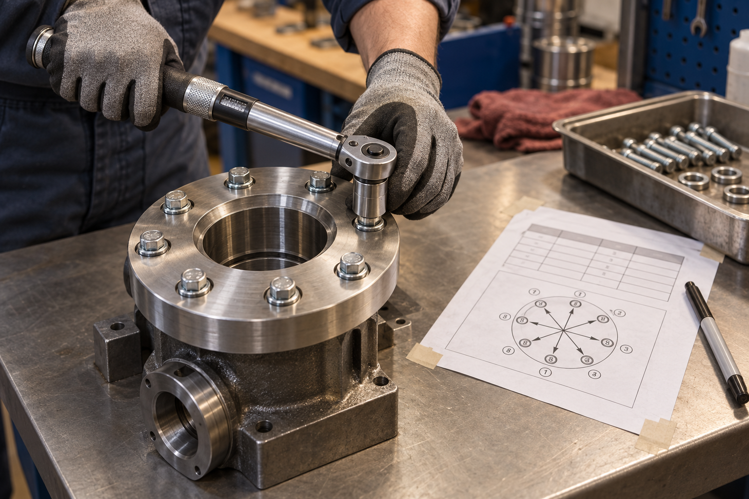
Mistake-proofing design: make it impossible to install incorrectly
More reliable than training and conscientiousness is mistake-proofing (poka-yoke). Common methods: asymmetrically arranged locating pins so that parts cannot be installed in reverse; offset bolt hole positions to prevent mixing up long and short bolts; keyed connectors so that inserting in the wrong orientation is impossible. Mistake-proofing design must be reflected in the geometry at the part machining stage, so that the assembly floor can truly be worry-free. If the parts themselves allow incorrect assembly and you rely on workers' self-inspection to catch it, the risk is merely postponed until it surfaces at the next process step.
After assembly is completed, there is usually functional testing or motion verification—whether rotation is smooth, whether the seal holds pressure, whether electrical continuity is present. The test station must clearly define the acceptance criteria and recording method; otherwise "it was tested" and "it passed the test" are two different things. Rework caused by incorrect assembly sequence often involves more than just disassembly and reassembly: interference-fit pressed parts may already have damaged mating surfaces after removal, repeated tightening of threads changes preload characteristics, and some parts can only be scrapped and remade. This is why assembly process documents are worth reviewing together before machining scheduling.
Common failure modes: from machining to assembly, problems often span stages
Dimensionally acceptable but won't assemble: the tolerance allocation account wasn't settled
Deformation after assembly: machining stress acts up only during tightening
Thread stripping and fatigue fracture: hidden and costly
Frequently asked questions
The following questions are basically the ones readers most often ask after reading the preceding text: how to set tolerances, how to save on fixturing, how to configure inspection, and how to discover assembly interference in advance. The answers follow the judgment logic of the preceding text; for specific values, please confirm according to the drawings and actual process.
For dimensions without tolerances marked on the drawing, what should be followed during machining?
Follow the general tolerance standard; the specific grade is specified by the drawing title block or technical agreement. A common practice is to control linear dimensions to a medium precision grade, but different standards (GB/T 1804, ISO 2768, etc.) have different values and cannot be assumed. A more reliable approach is: separately mark the fit dimensions that affect assembly and leave the rest open. The statement mentioned earlier that "tolerances are not better the tighter they are" especially holds for untoleranced dimensions—making everything to tight tolerances will jump costs up a tier, while assembly does not need to be that tight.
For thin-wall parts deforming after machining, is it a fixturing problem or insufficient stress relief?
Both are possible, and they often exist simultaneously. The recommended order of judgment is: first check whether clamping force is too high and whether clamping points press on weak-rigidity areas; then check whether the blank has residual stress and whether stress relief or natural aging was arranged after rough machining. When discussing datums and fixturing earlier, it was mentioned that errors can be generated before the workpiece is even cut—springback after clamping release is a typical manifestation. If the deformation direction is consistent across the same batch of parts, it leans more toward fixturing or process sequence; if the direction is random, it leans more toward internal material stress. During troubleshooting, it is best to keep dimensional records of semi-finished products after rough machining so that you can distinguish which stage introduced it.
During assembly, a part is found that won't fit. Should the part be changed or the assembly method?
Don't rush to change either side first; confirm how large the interference is and whether it's a single-part issue or a batch issue. If it's a single out-of-tolerance part, reworking or selective fitting is usually fastest; if it's batch-wide, it means the tolerance allocation or datum chain has a problem, and changing the assembly method will only mask it. As mentioned earlier when discussing the assembly stage, assembly is not a passive recipient of machining—difficulty can be reduced at the design stage through tolerance allocation, adjustable structures, or group selective fitting. Changing the part means going through machining and inspection again, while changing the assembly method may just mean a different tightening method or adding a guide, and the cost difference is large, so it's worth calculating clearly first.
Is a caliper sufficient for in-process inspection, and when must a CMM be used?
It depends on the tolerance and feature type. Calipers and micrometers are suitable for conventional dimensions and quick on-site judgment, but the measuring instrument itself has uncertainty, and selection must match the tolerance—using an instrument with insufficient resolution to measure a tight tolerance makes the measured value unreliable. Position tolerance, profile tolerance, coaxiality, and other geometric tolerances, as well as complex features that require establishing a datum system, usually require a CMM or dedicated gauges. As mentioned earlier when discussing inspection, the inspection method itself also has uncertainty, so the division of labor between first-article inspection and in-process sampling inspection should be determined in advance, rather than going back to supplement measurements after assembly problems arise.
What if the tightening torque and tightening sequence are not specified on the drawing?
Just because the drawing doesn't specify them doesn't mean you can tighten however you like. Multi-bolt connections usually have a recommended tightening sequence (such as diagonal, stepwise loading), the purpose being to make the force on the connected parts uniform and avoid local warping. Torque values are generally given by the design based on preload requirements; if they are indeed missing, you should go back to the design to confirm, rather than relying on feel on site. As mentioned earlier when discussing assembly process documents, the wrong sequence can lead to rework or even scrapping of parts—especially for thin sheets or plastic parts, one overtightening can crush them. Such parameters should be written into the assembly process card, rather than left in the experience of veteran workers.
Key takeaways
- Tolerance is a cost switch: being achievable does not mean it should be specified—before annotating, think clearly about which dimensions truly need to be tight and which are merely tightened out of habit
- Fixturing itself is a source of error, especially for thin-walled and slender parts—cutting forces and clamping forces deform the workpiece first, then cause dimensions to exceed tolerance
- Inconsistent datums cause tolerances to stack up layer by layer, and interference during assembly is often seeded at the machining stage
- Assembly is not the endpoint of machining: fitting, selective assembly, and adjustable structures are margin measures that should be reserved at the design level
- Drawings only care about dimensions, assembly only cares about whether it fits—the manufacturability judgment between the two requires a common language



